2009 SUBARU TRIBECA Diff id
[x] Cancel search: Diff idPage 1917 of 2453
ME(H6DO)-51
Rear Chain Cover
MECHANICAL
18.Rear Chain Cover
A: REMOVAL
1) Remove the crank pulley.
2) Remove the front chain cover.
3) Remove the timing chain.
4) Remove the cam sprocket.
5) Remove the crank sprocket.
6) Remove the oil pump.
7) Remove the water pump.
8) Remove the rear chain cover.
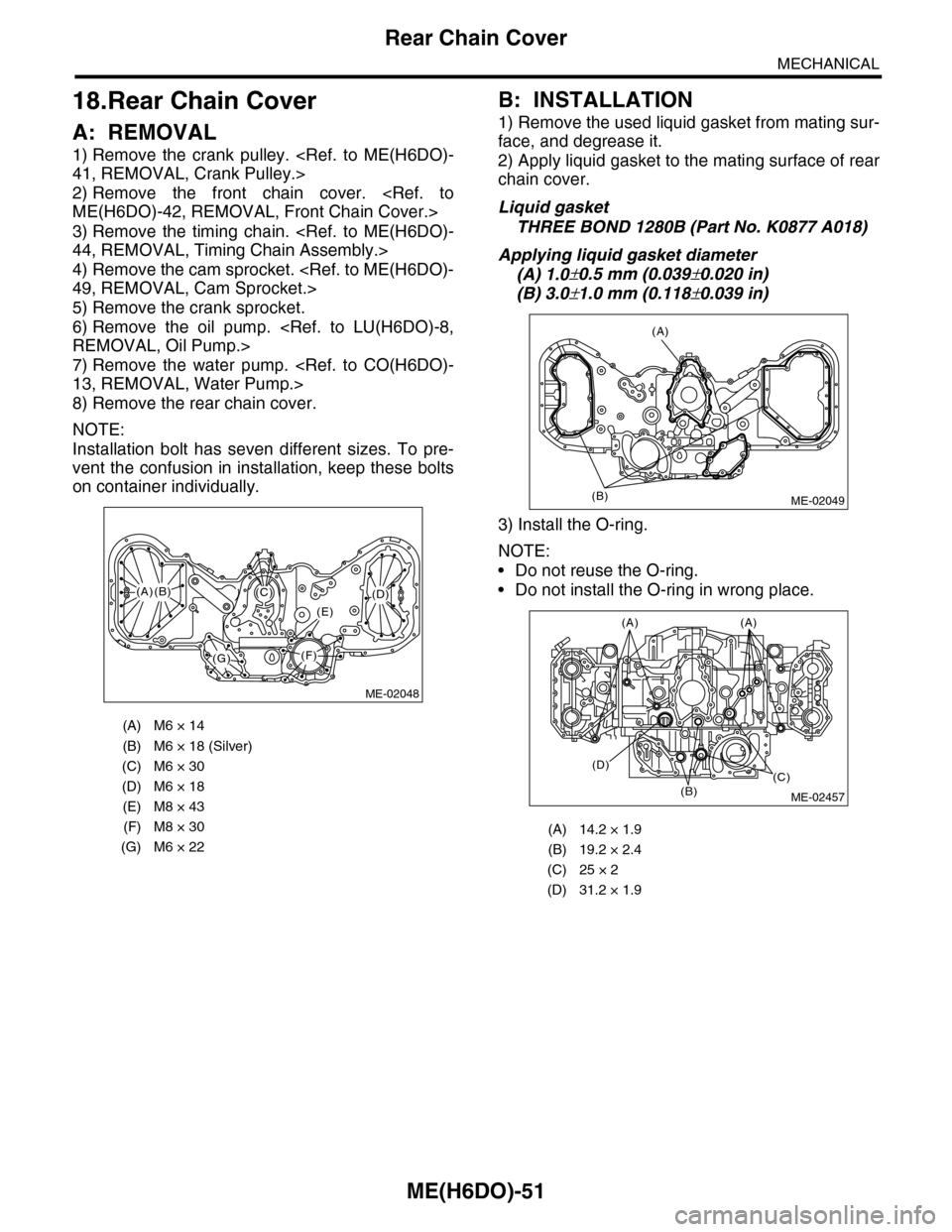
NOTE:
Installation bolt has seven different sizes. To pre-
vent the confusion in installation, keep these bolts
on container individually.
B: INSTALLATION
1) Remove the used liquid gasket from mating sur-
face, and degrease it.
2) Apply liquid gasket to the mating surface of rear
chain cover.
Liquid gasket
THREE BOND 1280B (Part No. K0877 A018)
Applying liquid gasket diameter
(A) 1.0±0.5 mm (0.039±0.020 in)
(B) 3.0±1.0 mm (0.118±0.039 in)
3) Install the O-ring.
NOTE:
•Do not reuse the O-ring.
•Do not install the O-ring in wrong place.
(A) M6 × 14
(B) M6 × 18 (Silver)
(C) M6 × 30
(D) M6 × 18
(E) M8 × 43
(F) M8 × 30
(G) M6 × 22
ME-02048
(F)
(C)(D)
(E)
(G)
(A)(B)
(A) 14.2 × 1.9
(B) 19.2 × 2.4
(C) 25 × 2
(D) 31.2 × 1.9
(A)
(B)ME-02049
(B)
(D)(C)
(A)(A)
ME-02457
Page 1927 of 2453
ME(H6DO)-61
Cylinder Head
MECHANICAL
5. VALVE SPRING
1) Check the valve springs for damage, free length,
and tension. Replace the valve spring if it is not
within the standard value presented in the table.
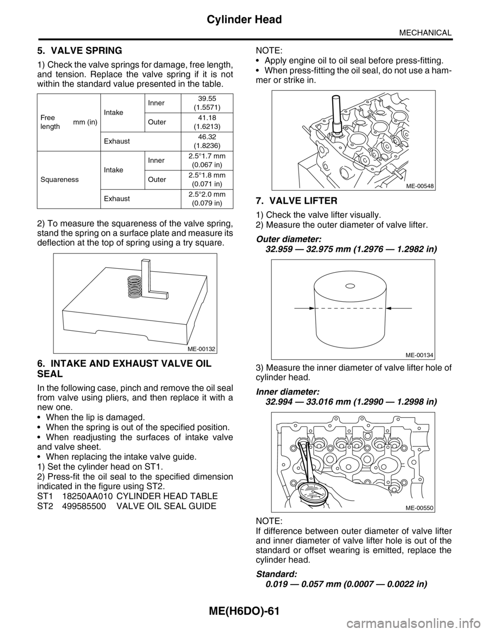
2) To measure the squareness of the valve spring,
stand the spring on a surface plate and measure its
deflection at the top of spring using a try square.
6. INTAKE AND EXHAUST VALVE OIL
SEAL
In the following case, pinch and remove the oil seal
from valve using pliers, and then replace it with a
new one.
•When the lip is damaged.
•When the spring is out of the specified position.
•When readjusting the surfaces of intake valve
and valve sheet.
•When replacing the intake valve guide.
1) Set the cylinder head on ST1.
2) Press-fit the oil seal to the specified dimension
indicated in the figure using ST2.
ST1 18250AA010 CYLINDER HEAD TABLE
ST2 499585500 VALVE OIL SEAL GUIDE
NOTE:
•Apply engine oil to oil seal before press-fitting.
•When press-fitting the oil seal, do not use a ham-
mer or strike in.
7. VALVE LIFTER
1) Check the valve lifter visually.
2) Measure the outer diameter of valve lifter.
Outer diameter:
32.959 — 32.975 mm (1.2976 — 1.2982 in)
3) Measure the inner diameter of valve lifter hole of
cylinder head.
Inner diameter:
32.994 — 33.016 mm (1.2990 — 1.2998 in)
NOTE:
If difference between outer diameter of valve lifter
and inner diameter of valve lifter hole is out of the
standard or offset wearing is emitted, replace the
cylinder head.
Standard:
0.019 — 0.057 mm (0.0007 — 0.0022 in)
Fr e e
lengthmm (in)
Intake
Inner39.55
(1.5571)
Outer41.18
(1.6213)
Exhaust46.32
(1.8236)
Squareness
Intake
Inner2.5°1.7 mm
(0.067 in)
Outer2.5°1.8 mm
(0.071 in)
Exhaust2.5°2.0 mm
(0.079 in)
ME-00132
ME-00548
ME-00134
ME-00550
Page 1929 of 2453
ME(H6DO)-63
Cylinder Block
MECHANICAL
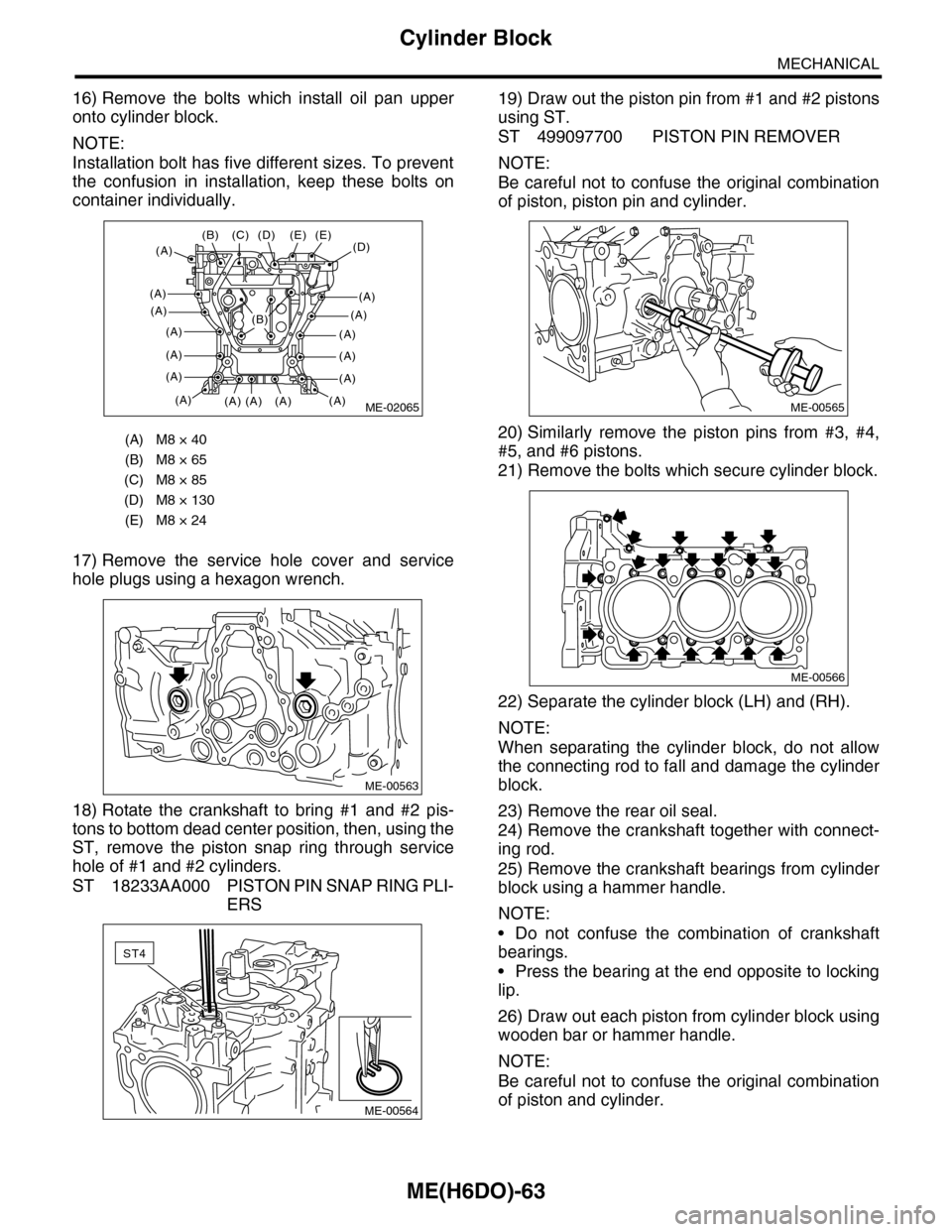
16) Remove the bolts which install oil pan upper
onto cylinder block.
NOTE:
Installation bolt has five different sizes. To prevent
the confusion in installation, keep these bolts on
container individually.
17) Remove the service hole cover and service
hole plugs using a hexagon wrench.
18) Rotate the crankshaft to bring #1 and #2 pis-
tons to bottom dead center position, then, using the
ST, remove the piston snap ring through service
hole of #1 and #2 cylinders.
ST 18233AA000 PISTON PIN SNAP RING PLI-
ERS
19) Draw out the piston pin from #1 and #2 pistons
using ST.
ST 499097700 PISTON PIN REMOVER
NOTE:
Be careful not to confuse the original combination
of piston, piston pin and cylinder.
20) Similarly remove the piston pins from #3, #4,
#5, and #6 pistons.
21) Remove the bolts which secure cylinder block.
22) Separate the cylinder block (LH) and (RH).
NOTE:
When separating the cylinder block, do not allow
the connecting rod to fall and damage the cylinder
block.
23) Remove the rear oil seal.
24) Remove the crankshaft together with connect-
ing rod.
25) Remove the crankshaft bearings from cylinder
block using a hammer handle.
NOTE:
•Do not confuse the combination of crankshaft
bearings.
•Press the bearing at the end opposite to locking
lip.
26) Draw out each piston from cylinder block using
wooden bar or hammer handle.
NOTE:
Be careful not to confuse the original combination
of piston and cylinder.
(A) M8 × 40
(B) M8 × 65
(C) M8 × 85
(D) M8 × 130
(E) M8 × 24
ME-02065
(D)(E)
(A)
(A)
(A)
(A)
(A)
(A)
(A)
(E)
(A)(A)(A)
(C)(B)
(A)
(D)
(A)
(A)
(A)
(A)
(A)
(B)
ME-00563
ST4
ME-00564
ME-00565
ME-00566
Page 1938 of 2453
ME(H6DO)-72
Cylinder Block
MECHANICAL
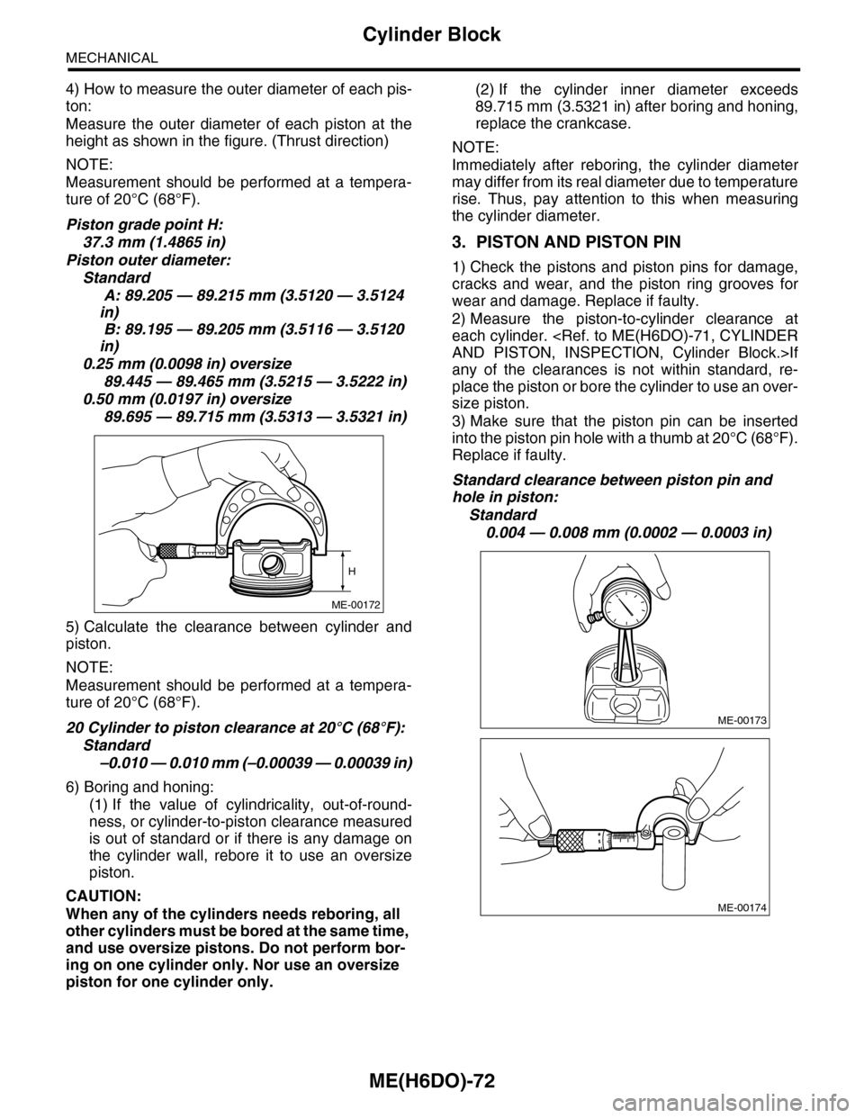
4) How to measure the outer diameter of each pis-
ton:
Measure the outer diameter of each piston at the
height as shown in the figure. (Thrust direction)
NOTE:
Measurement should be performed at a tempera-
ture of 20°C (68°F).
Piston grade point H:
37.3 mm (1.4865 in)
Piston outer diameter:
Standard
A: 89.205 — 89.215 mm (3.5120 — 3.5124
in)
B: 89.195 — 89.205 mm (3.5116 — 3.5120
in)
0.25 mm (0.0098 in) oversize
89.445 — 89.465 mm (3.5215 — 3.5222 in)
0.50 mm (0.0197 in) oversize
89.695 — 89.715 mm (3.5313 — 3.5321 in)
5) Calculate the clearance between cylinder and
piston.
NOTE:
Measurement should be performed at a tempera-
ture of 20°C (68°F).
20 Cylinder to piston clearance at 20°C (68°F):
Standard
–0.010 — 0.010 mm (–0.00039 — 0.00039 in)
6) Boring and honing:
(1) If the value of cylindricality, out-of-round-
ness, or cylinder-to-piston clearance measured
is out of standard or if there is any damage on
the cylinder wall, rebore it to use an oversize
piston.
CAUTION:
When any of the cylinders needs reboring, all
other cylinders must be bored at the same time,
and use oversize pistons. Do not perform bor-
ing on one cylinder only. Nor use an oversize
piston for one cylinder only.
(2) If the cylinder inner diameter exceeds
89.715 mm (3.5321 in) after boring and honing,
replace the crankcase.
NOTE:
Immediately after reboring, the cylinder diameter
may differ from its real diameter due to temperature
rise. Thus, pay attention to this when measuring
the cylinder diameter.
3. PISTON AND PISTON PIN
1) Check the pistons and piston pins for damage,
cracks and wear, and the piston ring grooves for
wear and damage. Replace if faulty.
2) Measure the piston-to-cylinder clearance at
each cylinder.
any of the clearances is not within standard, re-
place the piston or bore the cylinder to use an over-
size piston.
3) Make sure that the piston pin can be inserted
into the piston pin hole with a thumb at 20°C (68°F).
Replace if faulty.
Standard clearance between piston pin and
hole in piston:
Standard
0.004 — 0.008 mm (0.0002 — 0.0003 in)
ME-00172
H
ME-00173
ME-00174
Page 1984 of 2453
SC(H6DO)-26
Battery
STARTING/CHARGING SYSTEMS
3. SPECIFIC GRAVITY OF ELECTROLYTE
1) Measure specific gravity of electrolyte using a
hydrometer and a thermometer.
Specific gravity varies with temperature of electro-
lyte so that it must be corrected at 20°C (68°F) us-
ing the following equation:
S20 = St + 0.0007 × (t – 20)
S20: Specific gravity corrected at electrolyte
temperature of 20°C (68°F)
St: Measured specific gravity
t: Measured temperature (°C)
Determine whether or not battery must be
charged, according to corrected specific
gravity.
Standard specific gravity: 1.220 — 1.290
[20°C (68°F)]
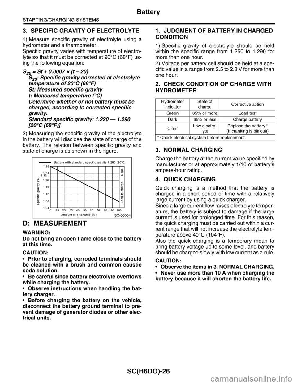
2) Measuring the specific gravity of the electrolyte
in the battery will disclose the state of charge of the
battery. The relation between specific gravity and
state of charge is as shown in the figure.
D: MEASUREMENT
WARNING:
Do not bring an open flame close to the battery
at this time.
CAUTION:
•Prior to charging, corroded terminals should
be cleaned with a brush and common caustic
soda solution.
•Be careful since battery electrolyte overflows
while charging the battery.
•Observe instructions when handling the bat-
tery charger.
•Before charging the battery on the vehicle,
disconnect the battery ground terminal to pre-
vent damage of generator diodes or other elec-
trical units.
1. JUDGMENT OF BATTERY IN CHARGED
CONDITION
1) Specific gravity of electrolyte should be held
within the specific range from 1.250 to 1.290 for
more than one hour.
2) Voltage per battery cell should be held at a spe-
cific value in a range from 2.5 to 2.8 V for more than
one hour.
2. CHECK CONDITION OF CHARGE WITH
HYDROMETER
3. NORMAL CHARGING
Charge the battery at the current value specified by
manufacturer or at approximately 1/10 of battery's
ampere-hour rating.
4. QUICK CHARGING
Quick charging is a method that the battery is
charged in a short period of time with a relatively
large current by using a quick charger.
Since a large current flow raises electrolyte temper-
ature, the battery is subject to damage if the large
current is used for prolonged time. For this reason,
the quick charging must be carried out within a cur-
rent range that will not increase the electrolyte tem-
perature above 40°C (104°F).
Also the quick charging is a temporary mean to
bring battery voltage up to some level, and battery
should be charged slowly with low current as a rule.
CAUTION:
•Observe the items in 3. NORMAL CHARGING.
•Never use more than 10 A when charging the
battery because it will shorten the battery life.
SC-00054
010 20 30 40 50 60 70 80 90 100
1.12
1.20
1.16
1.24
1.28
1.22
1.08
1.04
Amount of discharge (%)
Specific gravity ( C)
Battery with standard specific gravity 1,280 (20 C)
Good
Need to charge
Hydrometer
indicator
State of
chargeCorrective action
Green 65% or more Load test
Dark 65% or less Charge battery
ClearLow electro-
lyte
Replace the battery.*
(If cranking is difficult)
* Check electrical system before replacement.
Page 1986 of 2453
PM-3
Schedule
PERIODIC MAINTENANCE SERVICES
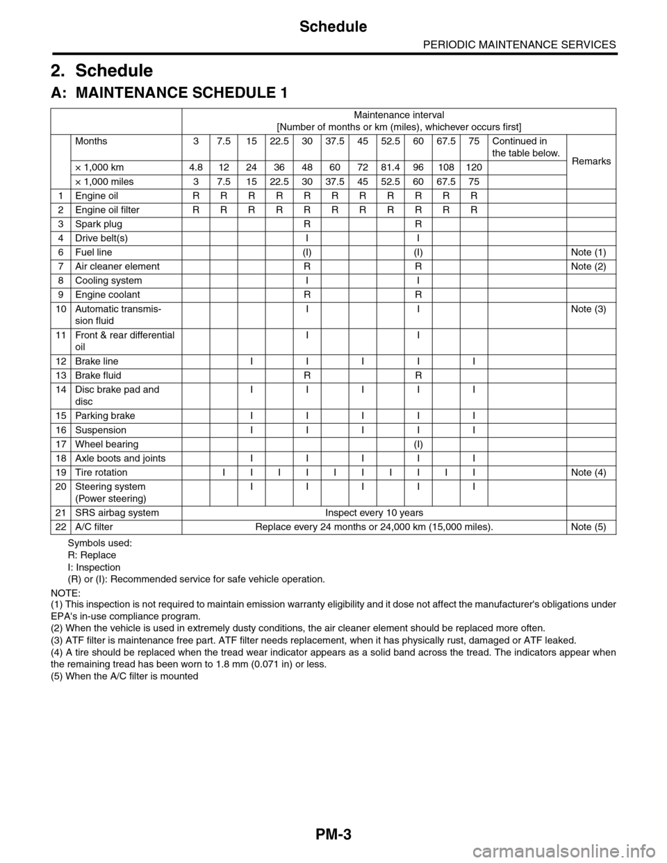
2. Schedule
A: MAINTENANCE SCHEDULE 1
Symbols used:
R: Replace
I: Inspection
(R) or (I): Recommended service for safe vehicle operation.
NOTE:(1) This inspection is not required to maintain emission warranty eligibility and it dose not affect the manufacturer's obligations under
EPA's in-use compliance program.
(2) When the vehicle is used in extremely dusty conditions, the air cleaner element should be replaced more often.
(3) ATF filter is maintenance free part. ATF filter needs replacement, when it has physically rust, damaged or ATF leaked.
(4) A tire should be replaced when the tread wear indicator appears as a solid band across the tread. The indicators appear when
the remaining tread has been worn to 1.8 mm (0.071 in) or less.
(5) When the A/C filter is mounted
Maintenance interval
[Number of months or km (miles), whichever occurs first]
Months 3 7.51522.53037.54552.56067.575Continued in
the table below.Remarks× 1,000 km 4.8 12 24 36 48 60 72 81.4 96 108 120
× 1,000 miles 3 7.5 15 22.5 30 37.5 45 52.5 60 67.5 75
1Engine oil R R R R R R R R R R R
2Engine oil filter R R R R R R R R R R R
3Spark plug R R
4Drive belt(s) I I
6Fuel line (I) (I) Note (1)
7Air cleaner element R R Note (2)
8Cooling system I I
9Engine coolant R R
10 Automatic transmis-
sion fluid
I I Note (3)
11 Front & rear differential
oil
I I
12 Brake line I I I I I
13 Brake fluid R R
14 Disc brake pad and
disc
I I I I I
15 Parking brake I I I I I
16 Suspension I I I I I
17 Wheel bearing (I)
18 Axle boots and joints I I I I I
19 Tire rotation I I I I I I I I I I Note (4)
20 Steering system
(Power steering)
I I I I I
21 SRS airbag system Inspect every 10 years
22 A/C filter Replace every 24 months or 24,000 km (15,000 miles). Note (5)
Page 1987 of 2453
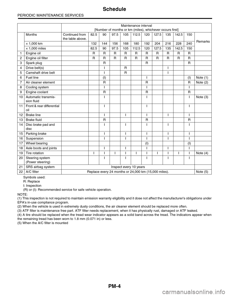
PM-4
Schedule
PERIODIC MAINTENANCE SERVICES
Symbols used:
R: Replace
I: Inspection
(R) or (I): Recommended service for safe vehicle operation.
NOTE:(1) This inspection is not required to maintain emission warranty eligibility and it dose not affect the manufacturer's obligations under
EPA's in-use compliance program.
(2) When the vehicle is used in extremely dusty conditions, the air cleaner element should be replaced more often.
(3) ATF filter is maintenance free part. ATF filter needs replacement, when it has physically rust, damaged or ATF leaked.
(4) A tire should be replaced when the tread wear indicator appears as a solid band across the tread. The indicators appear when
the remaining tread has been worn to 1.8 mm (0.071 in) or less.
(5) When the A/C filter is mounted
Maintenance interval
[Number of months or km (miles), whichever occurs first]
Months Continued from
the table above.
82.5 90 97.5 105112.5120127.5135142.5150
Remarks× 1,000 km 132 144 156 168 180 192 204 216 228 240
× 1,000 miles 82.5 90 97.5 105112.5120127.5135142.5150
1Engine oil R R R R R R R R R R
2Engine oil filter R R R R R R R R R R
3Spark plug R R R
4Drive belt(s) I R I
5Camshaft drive belt I R I
6Fuel line (I) I (I) Note (1)
7Air cleaner element R R R Note (2)
8Cooling system I I I
9Engine coolant R R R
10 Automatic transmis-
sion fluid
I I INote (3)
11 Front & rear differential
oil
I I I
12 Brake line I I I I I
13 Brake fluid R R R
14 Disc brake pad and
disc
I I I I I
15 Parking brake I I I I I
16 Suspension I I I I I
17 Wheel bearing (I) (I)
18 Axle boots and joints I I I I I
19 Tire rotation I I I I I I I I I I Note (4)
20 Steering system
(Power steering)
I I I I I
21 SRS airbag system Inspect every 10 years
22 A/C filter Replace every 24 months or 24,000 km (15,000 miles). Note (5)
Page 1988 of 2453
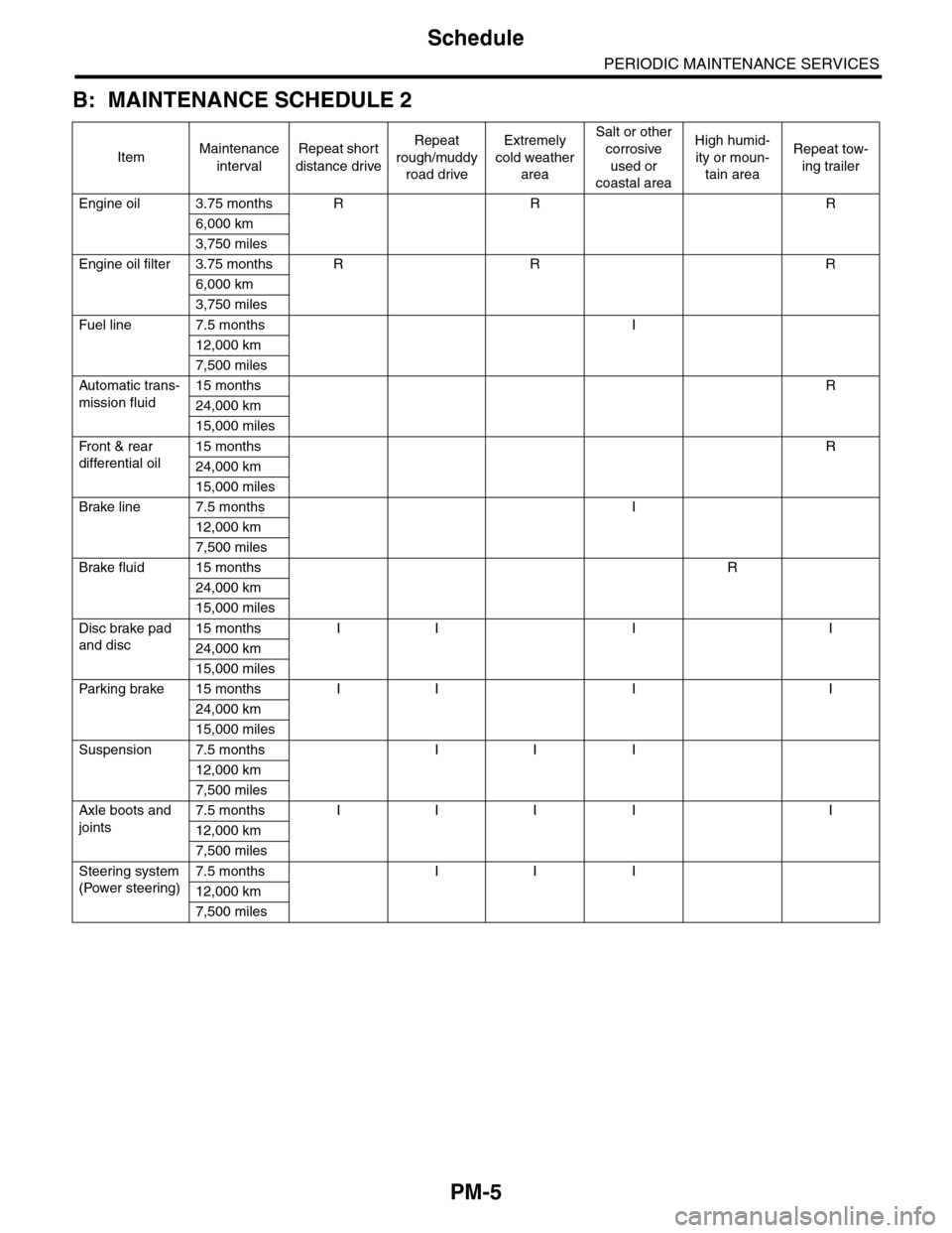
PM-5
Schedule
PERIODIC MAINTENANCE SERVICES
B: MAINTENANCE SCHEDULE 2
ItemMaintenance
interval
Repeat short
distance drive
Repeat
rough/muddy
road drive
Extremely
cold weather
area
Salt or other
corrosive
used or
coastal area
High humid-
ity or moun-
tain area
Repeat tow-
ing trailer
Engine oil 3.75 months R R R
6,000 km
3,750 miles
Engine oil filter 3.75 months R R R
6,000 km
3,750 miles
Fuel line 7.5 months I
12,000 km
7,500 miles
Automatic trans-
mission fluid
15 months R
24,000 km
15,000 miles
Fr o nt & r ea r
differential oil
15 months R
24,000 km
15,000 miles
Brake line 7.5 months I
12,000 km
7,500 miles
Brake fluid 15 months R
24,000 km
15,000 miles
Disc brake pad
and disc
15 months I I I I
24,000 km
15,000 miles
Par king brake 15 months I I I I
24,000 km
15,000 miles
Suspension 7.5 months I I I
12,000 km
7,500 miles
Axle boots and
joints
7.5 months I I I I I
12,000 km
7,500 miles
Steering system
(Power steering)
7.5 months I I I
12,000 km
7,500 miles