2009 SUBARU TRIBECA Diff id
[x] Cancel search: Diff idPage 2226 of 2453
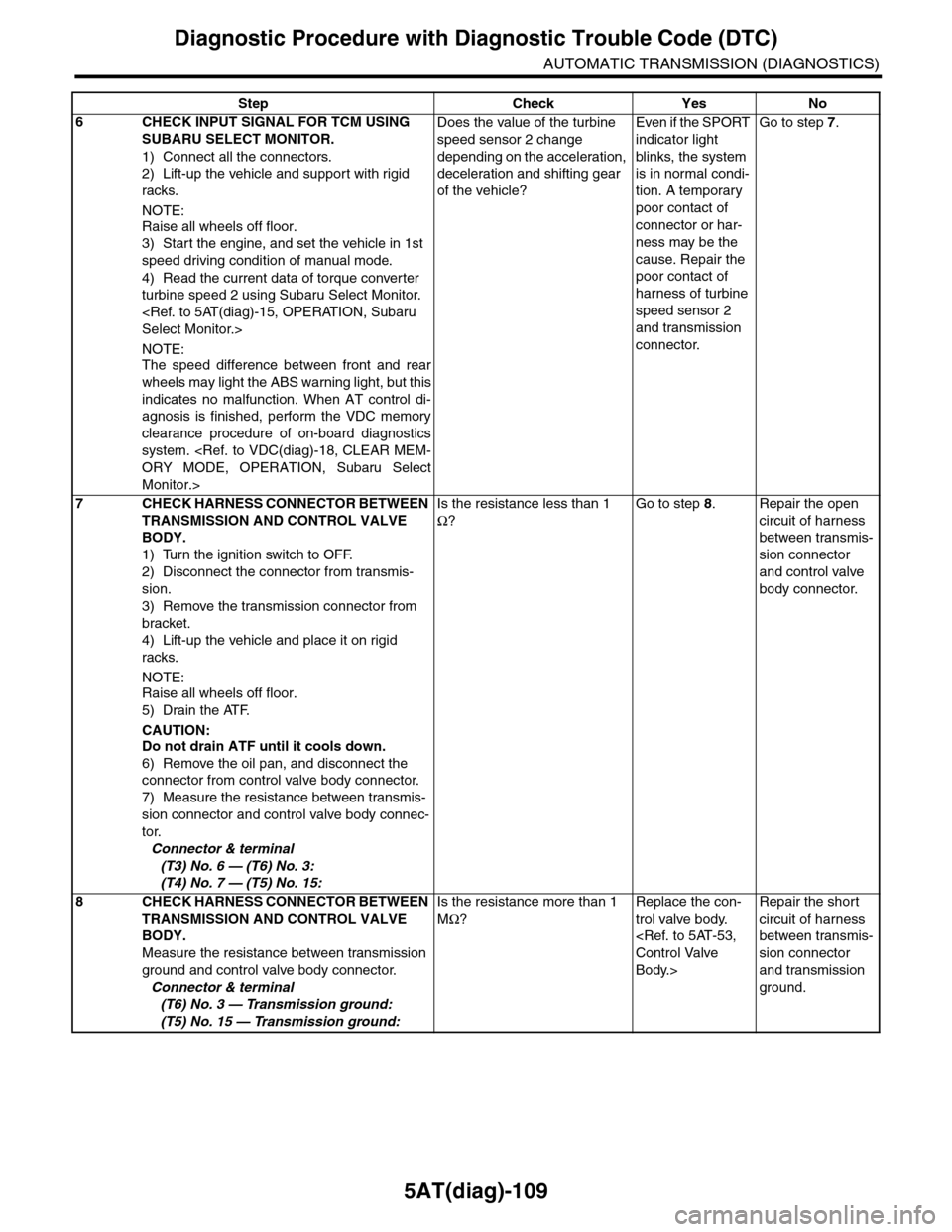
5AT(diag)-109
Diagnostic Procedure with Diagnostic Trouble Code (DTC)
AUTOMATIC TRANSMISSION (DIAGNOSTICS)
6CHECK INPUT SIGNAL FOR TCM USING
SUBARU SELECT MONITOR.
1) Connect all the connectors.
2) Lift-up the vehicle and support with rigid
racks.
NOTE:
Raise all wheels off floor.
3) Start the engine, and set the vehicle in 1st
speed driving condition of manual mode.
4) Read the current data of torque converter
turbine speed 2 using Subaru Select Monitor.
NOTE:The speed difference between front and rear
wheels may light the ABS warning light, but this
indicates no malfunction. When AT control di-
agnosis is finished, perform the VDC memory
clearance procedure of on-board diagnostics
system.
Monitor.>
Does the value of the turbine
speed sensor 2 change
depending on the acceleration,
deceleration and shifting gear
of the vehicle?
Even if the SPORT
indicator light
blinks, the system
is in normal condi-
tion. A temporary
poor contact of
connector or har-
ness may be the
cause. Repair the
poor contact of
harness of turbine
speed sensor 2
and transmission
connector.
Go to step 7.
7CHECK HARNESS CONNECTOR BETWEEN
TRANSMISSION AND CONTROL VALVE
BODY.
1) Turn the ignition switch to OFF.
2) Disconnect the connector from transmis-
sion.
3) Remove the transmission connector from
bracket.
4) Lift-up the vehicle and place it on rigid
racks.
NOTE:
Raise all wheels off floor.
5) Drain the ATF.
CAUTION:Do not drain ATF until it cools down.
6) Remove the oil pan, and disconnect the
connector from control valve body connector.
7) Measure the resistance between transmis-
sion connector and control valve body connec-
tor.
Connector & terminal
(T3) No. 6 — (T6) No. 3:
(T4) No. 7 — (T5) No. 15:
Is the resistance less than 1
Ω?
Go to step 8.Repair the open
circuit of harness
between transmis-
sion connector
and control valve
body connector.
8CHECK HARNESS CONNECTOR BETWEEN
TRANSMISSION AND CONTROL VALVE
BODY.
Measure the resistance between transmission
ground and control valve body connector.
Connector & terminal
(T6) No. 3 — Transmission ground:
(T5) No. 15 — Transmission ground:
Is the resistance more than 1
MΩ?
Replace the con-
trol valve body.
Body.>
Repair the short
circuit of harness
between transmis-
sion connector
and transmission
ground.
Step Check Yes No
Page 2290 of 2453
WI-6
Basic Diagnostic Procedure
WIRING SYSTEM
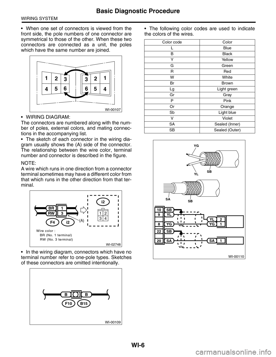
•When one set of connectors is viewed from the
front side, the pole numbers of one connector are
symmetrical to those of the other. When these two
connectors are connected as a unit, the poles
which have the same number are joined.
•WIRING DIAGRAM:
The connectors are numbered along with the num-
ber of poles, external colors, and mating connec-
tions in the accompanying list.
•The sketch of each connector in the wiring dia-
gram usually shows the (A) side of the connector.
The relationship between the wire color, terminal
number and connector is described in the figure.
NOTE:
A wire which runs in one direction from a connector
terminal sometimes may have a different color from
that which runs in the other direction from that ter-
minal.
•In the wiring diagram, connectors which have no
terminal number refer to one-pole types. Sketches
of these connectors are omitted intentionally.
•The following color codes are used to indicate
the colors of the wires.
WI-00107
112233
445566
WI-02748
Wire color :BR (No. 1 terminal)RW (No. 3 terminal)
i2
34
12
BR
RW
i2F4
1
3
(A)
WI-00109
BB
B15F10
Color code Color
LBlue
BBlack
YYellow
GGreen
RRed
WWhite
Br Brown
Lg Light green
Gr Gray
PPink
Or Orange
Sb Light blue
VViolet
SA Sealed (Inner)
SB Sealed (Outer)
WI-00110
YL 2
YG 1
SB10
YL9
YG8
SA 1
SB22
SA20
YG
YLSB
SBSA
Page 2291 of 2453
WI-7
Basic Diagnostic Procedure
WIRING SYSTEM
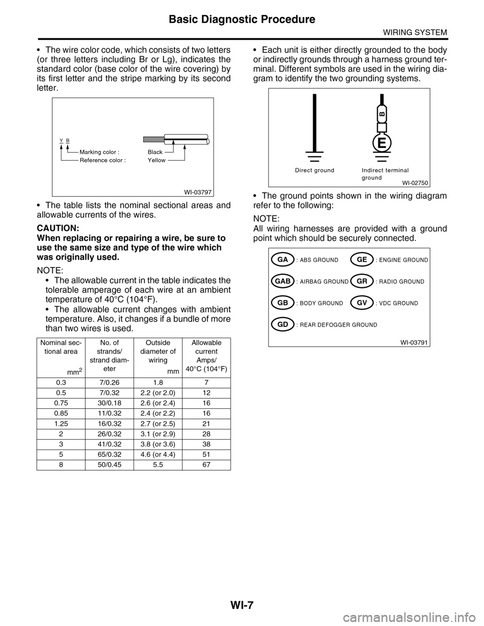
•The wire color code, which consists of two letters
(or three letters including Br or Lg), indicates the
standard color (base color of the wire covering) by
its first letter and the stripe marking by its second
letter.
•The table lists the nominal sectional areas and
allowable currents of the wires.
CAUTION:
When replacing or repairing a wire, be sure to
use the same size and type of the wire which
was originally used.
NOTE:
•The allowable current in the table indicates the
tolerable amperage of each wire at an ambient
temperature of 40°C (104°F).
•The allowable current changes with ambient
temperature. Also, it changes if a bundle of more
than two wires is used.
•Each unit is either directly grounded to the body
or indirectly grounds through a harness ground ter-
minal. Different symbols are used in the wiring dia-
gram to identify the two grounding systems.
•The ground points shown in the wiring diagram
refer to the following:
NOTE:
All wiring harnesses are provided with a ground
point which should be securely connected.
Nominal sec-
tional area
No. of
strands/
strand diam-
eter
Outside
diameter of
wiring
Allowable
current
Amps/
40°C (104°F)mm2mm
0.3 7/0.26 1.8 7
0.5 7/0.32 2.2 (or 2.0) 12
0.75 30/0.18 2.6 (or 2.4) 16
0.85 11/0.32 2.4 (or 2.2) 16
1.25 16/0.32 2.7 (or 2.5) 21
226/0.323.1 (or 2.9)28
341/0.323.8 (or 3.6)38
565/0.324.6 (or 4.4)51
850/0.455.5 67
WI-03797
YB
BlackMarking color :
Reference color : Yellow
WI-02750
Direct ground Indirect terminalground
B
WI-03791
: ABS GROUNDGA
: AIRBAG GROUNDGAB
: BODY GROUNDGB
: ENGINE GROUNDGE
: RADIO GROUNDGR
: VDC GROUNDGV
: REAR DEFOGGER GROUNDGD
Page 2295 of 2453
WI-11
Basic Diagnostic Procedure
WIRING SYSTEM
1. RELAY
A symbol used to indicate a relay.
2. CONNECTOR 1
The sketch of the connector indicates the one-pole
types.
3. WIRING CONNECTION
Some wiring diagrams are indicated in foldouts for
convenience. Wiring destinations are indicated
where necessary by corresponding symbols.
(When two pages are needed for clear indication)
4. FUSE NO. & RATING
The “FUSE No. & RATING“ corresponds with that
used in the fuse box (main fuse box, fuse and joint
box).
5. CONNECTOR 2
•Each connector is indicated by a symbol.
•Each terminal number is indicated in the corre-
sponding wiring diagram in an abbreviated form.
•For example, terminal number "G4" refers to No.
4 terminal of connector (G: F41) shown in the con-
nector sketch.
6. CONNECTOR SKETCH
•Each connector sketch clearly identifies the
shape and color of a connector as well as terminal
locations. Non-colored connectors are indicated in
white or natural color.
•When more than two types of connector number
are indicated in a connector sketch, it means that
the same type connectors are used.
7. GROUND
Each grounding point can be located easily by re-
ferring to the corresponding wiring harness.
8. DIODE
A symbol is used to indicate a diode.
9. WIRE TRACING ON EXTENDED WIRING
DIAGRAMS
For a wiring diagram extending over at least two
pages, a symbol (consisting of the same characters
with arrows), facilitates wire tracing from one page
to the next.
A ←→ B, B ←→ B
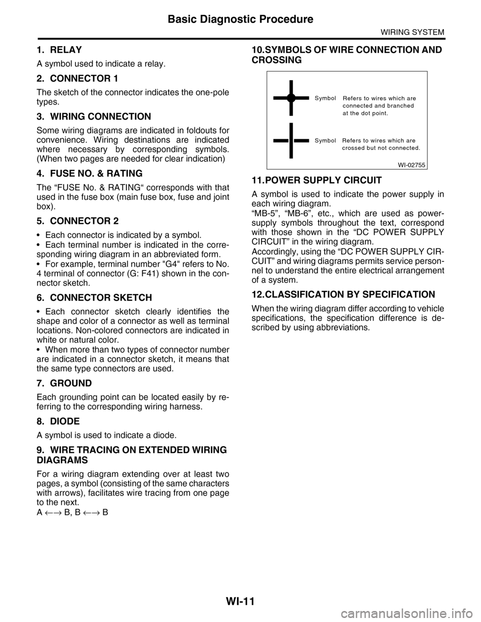
10.SYMBOLS OF WIRE CONNECTION AND
CROSSING
11.POWER SUPPLY CIRCUIT
A symbol is used to indicate the power supply in
each wiring diagram.
“MB-5”, “MB-6”, etc., which are used as power-
supply symbols throughout the text, correspond
with those shown in the “DC POWER SUPPLY
CIRCUIT” in the wiring diagram.
Accordingly, using the “DC POWER SUPPLY CIR-
CUIT” and wiring diagrams permits service person-
nel to understand the entire electrical arrangement
of a system.
12.CLASSIFICATION BY SPECIFICATION
When the wiring diagram differ according to vehicle
specifications, the specification difference is de-
scribed by using abbreviations.
WI-02755
Symbol
Symbol Refers to wires which arecrossed but not connected.
Refers to wires which areconnected and branchedat the dot point.
Page 2416 of 2453
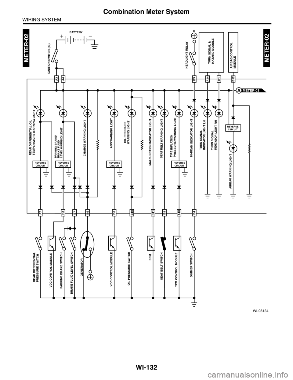
WI-132
Combination Meter System
WIRING SYSTEM
WI-08134
METER-02METER-02
ECM
TPM
CONTROL M
ODULE
VDC CONTROL M
ODULE
OIL P
RESSURE SW
ITCH
GENERATOR
BRAKE FLU
ID LEV
EL SWITCH
AIRBAG WARNING LIGHT
HEADLIGHT RELAYAIRBAG CONTROLMODULE
ABS WARNING LIGHT
CHARGE WARNING LIGHTPARKING BRAKE/BRAKE FLUIDLEVEL WARNING LIGHT
VDC CONTROL M
ODULE
PARKING BRAKE SWITCH
REAR DIFFE
RENTIAL
PRESSURE SWITCH
SEA
T BELT W
ARNING LIG
HT
SEAT BELT S
WITCH
A3
IGNITION SWITCH (IG)
A4
REVERSECIRCUIT
OIL PRESSUREWARNING LIGHT
MALFUNCTION INDICATOR LIGHT
HI-BEAM INDICATOR LIGHT
TURN SIGNAL &HAZARD MODULE
TURN SIGNALINDICATOR LIGHT LHTURN SIGNALINDICATOR LIGHT RH
REVERSECIRCUIT
REVERSECIRCUIT
B
B3A14B1B12
METER-03A
BATTERY
B8B7B9B6B10B5B4B11
REAR DIFFERENTIAL OIL TEMPERATURE WARNING LIGHT
REVERSECIRCUIT
DIMMER SWITCH
TIRE INFLATION PRESSURE WARNING LIGHT
REVERSECIRCUIT
A10A7
Page 2432 of 2453
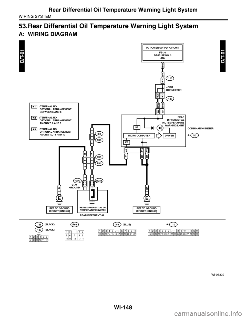
WI-148
Rear Differential Oil Temperature Warning Light System
WIRING SYSTEM
53.Rear Differential Oil Temperature Warning Light System
A: WIRING DIAGRAM
WI-08322
D/T-01D/T-01
48
i53
R98
R15
R60
1
Y
Y
YB
B
B
Y
Y
YBYBY
REARDIFFERENTIALOIL TEMPERATUREWARNING LIGHT
R234R277
REAR DIFFERENTIAL OILTEMPERATURE SWITCH
REAR DIFFERENTIAL
STAYGROUND
i10
19 20 2115 16 17 182223242526272829301234568910 11 12 13 147
A:R60
12
10115634897131412
123 8910411 12 13 14 15 16567171819202122
i53(BLUE)
123456789101112
i126(BLACK)
i127(BLACK)
: TERMINAL NO. OPTIONAL ARRANGEMENT BETWEEN 5 AND 6
1*
: TERMINAL NO. OPTIONAL ARRANGEMENT AMONG 7, 8 AND 9
2*
: TERMINAL NO. OPTIONAL ARRANGEMENT AMONG 10, 11 AND 12
3*COMBINATION METER
A: i10
I/F
I/F
MICRO COMPUTERDRIVER
A15A7A16
A3A4
BrW
BrW
BrW
BrW
JOINTCONNECTOR
i126
i127
3*
2*2*
BY
REF. TO GROUNDCIRCUIT [GND-05]
B
REF. TO GROUNDCIRCUIT [GND-05]
FB-36F/B FUSE NO. 5(IG)
TO POWER SUPPLY CIRCUIT
Page 2445 of 2453
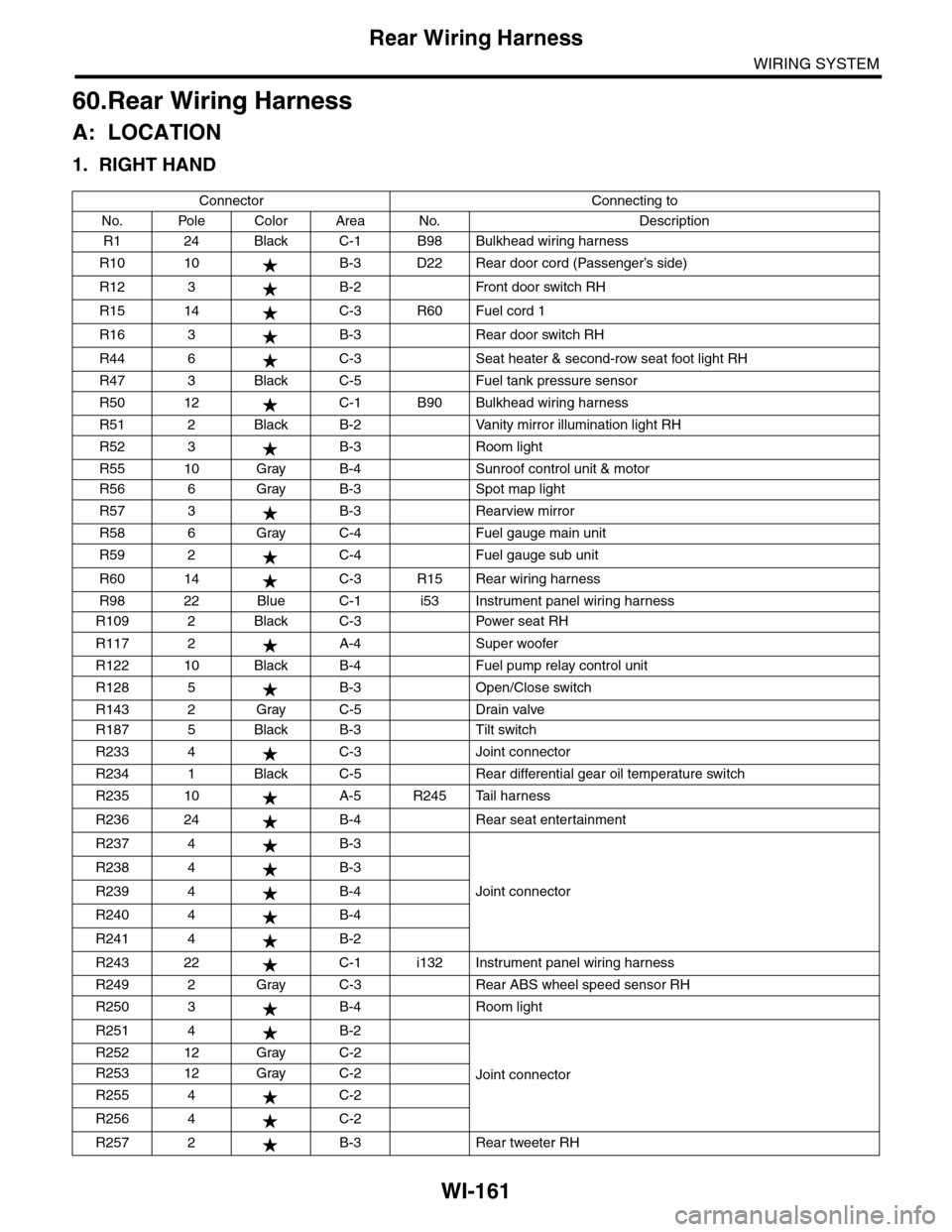
WI-161
Rear Wiring Harness
WIRING SYSTEM
60.Rear Wiring Harness
A: LOCATION
1. RIGHT HAND
Connector Connecting to
No. Pole Color Area No. Description
R1 24 Black C-1 B98 Bulkhead wiring harness
R10 10 B-3 D22 Rear door cord (Passenger’s side)
R12 3 B-2 Front door switch RH
R15 14 C-3 R60 Fuel cord 1
R16 3 B-3 Rear door switch RH
R44 6 C-3 Seat heater & second-row seat foot light RH
R47 3 Black C-5 Fuel tank pressure sensor
R50 12 C-1 B90 Bulkhead wiring harness
R51 2 Black B-2 Vanity mirror illumination light RH
R52 3 B-3 Room light
R55 10 Gray B-4 Sunroof control unit & motor
R56 6 Gray B-3 Spot map light
R57 3 B-3 Rearview mirror
R58 6 Gray C-4 Fuel gauge main unit
R59 2 C-4 Fuel gauge sub unit
R60 14 C-3 R15 Rear wiring harness
R98 22 Blue C-1 i53 Instrument panel wiring harness
R109 2 Black C-3 Power seat RH
R117 2 A-4 Super woofer
R122 10 Black B-4 Fuel pump relay control unit
R128 5 B-3 Open/Close switch
R143 2 Gray C-5 Drain valve
R187 5 Black B-3 Tilt switch
R233 4 C-3 Joint connector
R234 1 Black C-5 Rear differential gear oil temperature switch
R235 10 A-5 R245 Tail harness
R236 24 B-4 Rear seat entertainment
R237 4 B-3
Joint connector
R238 4 B-3
R239 4 B-4
R240 4 B-4
R241 4 B-2
R243 22 C-1 i132 Instrument panel wiring harness
R249 2 Gray C-3 Rear ABS wheel speed sensor RH
R250 3 B-4 Room light
R251 4 B-2
Joint connector
R252 12 Gray C-2
R253 12 Gray C-2
R255 4 C-2
R256 4 C-2
R257 2 B-3 Rear tweeter RH
Page 2446 of 2453
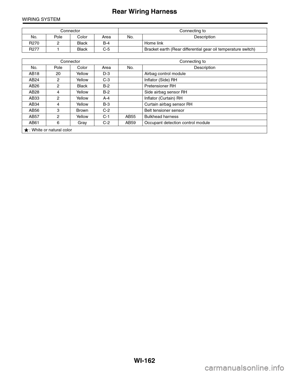
WI-162
Rear Wiring Harness
WIRING SYSTEM
R270 2 Black B-4 Home link
R277 1 Black C-5 Bracket earth (Rear differential gear oil temperature switch)
Connector Connecting to
No. Pole Color Area No. Description
AB18 20 Yellow D-3 Airbag control module
AB24 2 Yellow C-3 Inflator (Side) RH
AB26 2 Black B-2 Pretensioner RH
AB28 4 Yellow B-2 Side airbag sensor RH
AB33 2 Yellow A-4 Inflator (Curtain) RH
AB34 4 Yellow B-3 Curtain airbag sensor RH
AB56 3 Brown C-2 Belt tensioner sensor
AB57 2 Yellow C-1 AB55 Bulkhead harness
AB61 6 Gray C-2 AB59 Occupant detection control module
: White or natural color
Connector Connecting to
No. Pole Color Area No. Description