Page 1866 of 2453

LU(H6DO)-17
General Diagnostics Table
LUBRICATION
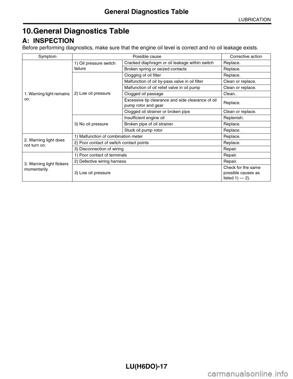
10.General Diagnostics Table
A: INSPECTION
Before performing diagnostics, make sure that the engine oil level is correct and no oil leakage exists.
Symptom Possible cause Corrective action
1. Warning light remains
on.
1) Oil pressure switch
failure
Cracked diaphragm or oil leakage within switch Replace.
Broken spring or seized contacts Replace.
2) Low oil pressure
Clogging of oil filter Replace.
Malfunction of oil by-pass valve in oil filter Clean or replace.
Malfunction of oil relief valve in oil pump Clean or replace.
Clogged oil passage Clean.
Excessive tip clearance and side clearance of oil
pump rotor and gearReplace.
Clogged oil strainer or broken pipe Clean or replace.
3) No oil pressure
Insufficient engine oil Replenish.
Broken pipe of oil strainer Replace.
Stuck oil pump rotor Replace.
2. Warning light does
not turn on.
1) Malfunction of combination meter Replace.
2) Poor contact of switch contact points Replace.
3) Disconnection of wiring Repair.
3. Warning light flickers
momentarily.
1) Poor contact of terminals Repair.
2) Defective wiring harness Repair.
3) Low oil pressure
Check for the same
possible causes as
listed 1) — 2).
Page 1937 of 2453

ME(H6DO)-71
Cylinder Block
MECHANICAL
E: INSPECTION
1. CYLINDER BLOCK
1) Visually check for cracks and damage. Especial-
ly, inspect the important parts using liquid pene-
trant tester.
2) Check the oil passages for clogging.
3) Inspect the crankcase surface that mates with
cylinder head for warping by using a straight edge.
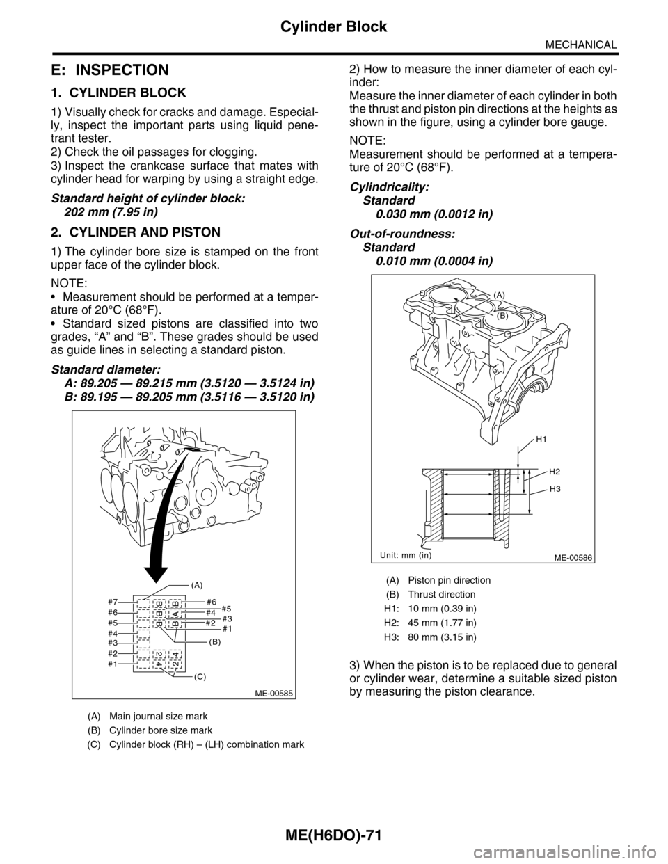
Standard height of cylinder block:
202 mm (7.95 in)
2. CYLINDER AND PISTON
1) The cylinder bore size is stamped on the front
upper face of the cylinder block.
NOTE:
•Measurement should be performed at a temper-
ature of 20°C (68°F).
•Standard sized pistons are classified into two
grades, “A” and “B”. These grades should be used
as guide lines in selecting a standard piston.
Standard diameter:
A: 89.205 — 89.215 mm (3.5120 — 3.5124 in)
B: 89.195 — 89.205 mm (3.5116 — 3.5120 in)
2) How to measure the inner diameter of each cyl-
inder:
Measure the inner diameter of each cylinder in both
the thrust and piston pin directions at the heights as
shown in the figure, using a cylinder bore gauge.
NOTE:
Measurement should be performed at a tempera-
ture of 20°C (68°F).
Cylindricality:
Standard
0.030 mm (0.0012 in)
Out-of-roundness:
Standard
0.010 mm (0.0004 in)
3) When the piston is to be replaced due to general
or cylinder wear, determine a suitable sized piston
by measuring the piston clearance.
(A) Main journal size mark
(B) Cylinder bore size mark
(C) Cylinder block (RH) – (LH) combination mark
#7 #6#5
#2#1
#4#3#6#5#4#3#2#1
BBB 2
42BAB4
(A)
(B)
(C)
ME-00585
(A) Piston pin direction
(B) Thrust direction
H1: 10 mm (0.39 in)
H2: 45 mm (1.77 in)
H3: 80 mm (3.15 in)
ME-00586
H1
H2
H3
Unit: mm (in)
(B)
(A)
Page 2002 of 2453

PM-19
Brake Line
PERIODIC MAINTENANCE SERVICES
13.Brake Line
A: INSPECTION
1. BRAKE LINE
1) Check for scratches, swelling, corrosion, traces
of fluid leakage on the brake hoses or pipe joints.
2) Check the possibility of adjacent parts interfering
with brake pipes/hoses during driving, and loose
connections/clamps.
3) Check any trace of fluid leakage, scratches, etc.
on master cylinder, wheel cylinder and pressure
control valve.
NOTE:
•When the brake fluid level in the reservoir tank is
lower than specified limit, the brake warning light
on the combination meter will come on.
•Visually check the brake hose for damage. (Use
a mirror where it is difficult to see)
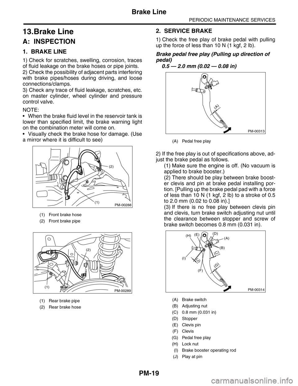
2. SERVICE BRAKE
1) Check the free play of brake pedal with pulling
up the force of less than 10 N (1 kgf, 2 lb).
Brake pedal free play (Pulling up direction of
pedal)
0.5 — 2.0 mm (0.02 — 0.08 in)
2) If the free play is out of specifications above, ad-
just the brake pedal as follows.
(1) Make sure the engine is off. (No vacuum is
applied to brake booster.)
(2) There should be play between brake boost-
er clevis and pin at brake pedal installing por-
tion. [Pulling up the brake pedal pad with a force
of less than 10 N (1 kgf, 2 lb) to a stroke of 0.5
to 2.0 mm (0.02 to 0.08 in).]
(3) If there is no free play between clevis pin
and clevis, turn brake switch adjusting nut until
the clearance between stopper and screw of
brake switch becomes 0.8 mm (0.031 in).
(1) Front brake hose
(2) Front brake pipe
(1) Rear brake pipe
(2) Rear brake hose
PM-00288
(2)
(1)
PM-00289(1)
(2)
(A) Pedal free play
(A) Brake switch
(B) Adjusting nut
(C) 0.8 mm (0.031 in)
(D) Stopper
(E) Clevis pin
(F) Clevis
(G) Pedal free play
(H) Lock nut
(I) Brake booster operating rod
(J) Play at pin
PM-00313
(A)
PM-00314
(G)
(A)(D)(E)
(B)
(C)
(F)
(J)(I)
(H)
Page 2140 of 2453
5AT(diag)-23
SPORT Indicator Light Display
AUTOMATIC TRANSMISSION (DIAGNOSTICS)
B: INSPECTION
DIAGNOSIS:
SPORT indicator light circuit is open or shorted.
TROUBLE SYMPTOM:
When the ignition switch is turned to ON (engine OFF), SPORT indicator light does not illuminate.
WIRING DIAGRAM:
AT-03284
34
2930
COMBINATIONMETER
i10
i84A:B280B:
A27A26
B20B30
43
TCMB54
BODY INTEGRATED UNIT
SPORT
BATTERY
MAIN SBF SBF-6
IGNITIONSWITCH
NO.5
E
i84
8765432122232120191615141312111093435333217301831292827262524
A:
B280
87654321
2223212019161514131211109173018292827262524
B:
B54
12789563410 11 1219 20 2113 14 15 16 17 18222324
i10
123456789101112131415161718192021222324252627282930
Page 2141 of 2453

5AT(diag)-24
SPORT Indicator Light Display
AUTOMATIC TRANSMISSION (DIAGNOSTICS)
Step Check Yes No
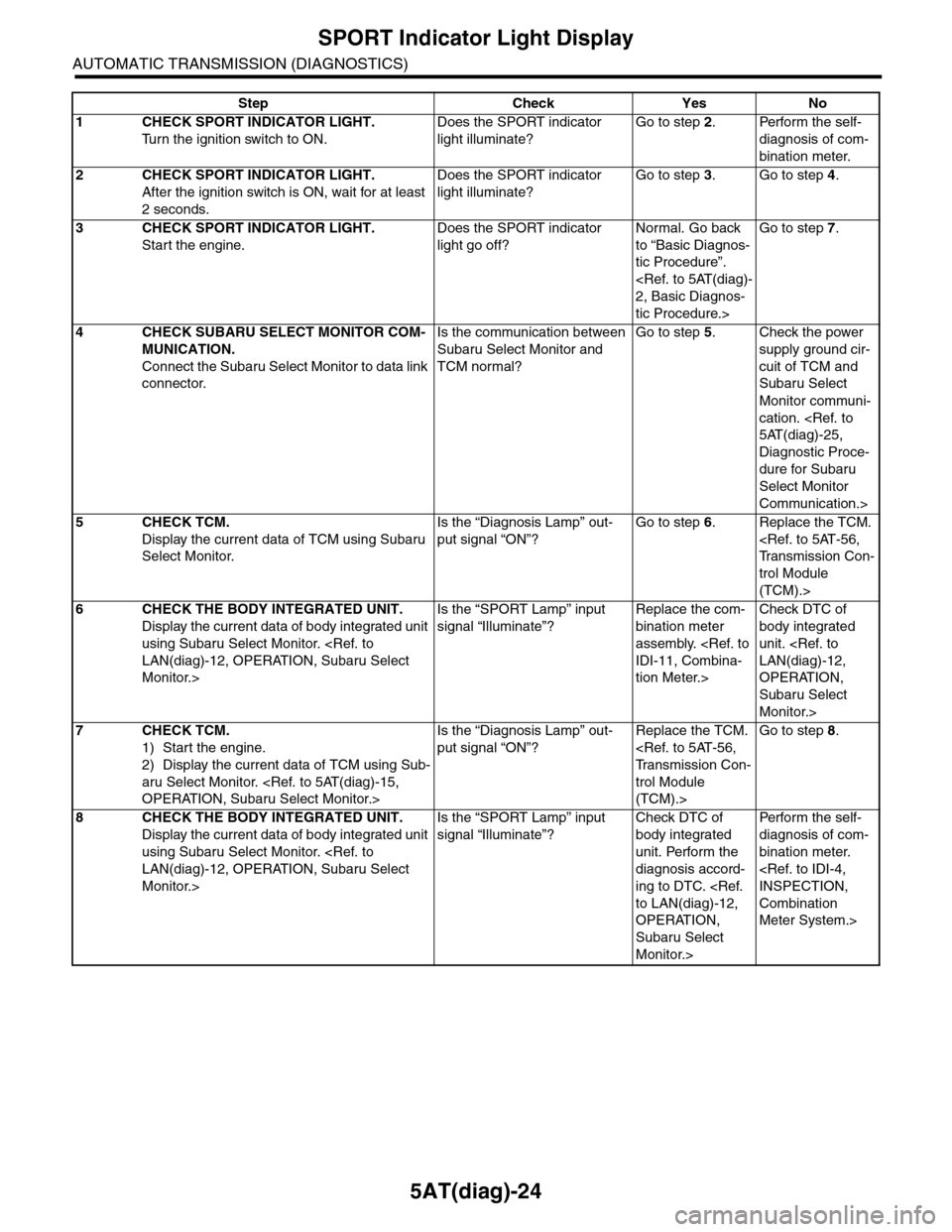
1CHECK SPORT INDICATOR LIGHT.
Tu r n t h e i g n i t i o n s w i t c h t o O N .
Does the SPORT indicator
light illuminate?
Go to step 2.Perform the self-
diagnosis of com-
bination meter.
2CHECK SPORT INDICATOR LIGHT.
After the ignition switch is ON, wait for at least
2 seconds.
Does the SPORT indicator
light illuminate?
Go to step 3.Go to step 4.
3CHECK SPORT INDICATOR LIGHT.
Start the engine.
Does the SPORT indicator
light go off?
Normal. Go back
to “Basic Diagnos-
tic Procedure”.
2, Basic Diagnos-
tic Procedure.>
Go to step 7.
4CHECK SUBARU SELECT MONITOR COM-
MUNICATION.
Connect the Subaru Select Monitor to data link
connector.
Is the communication between
Subaru Select Monitor and
TCM normal?
Go to step 5.Check the power
supply ground cir-
cuit of TCM and
Subaru Select
Monitor communi-
cation.
5AT(diag)-25,
Diagnostic Proce-
dure for Subaru
Select Monitor
Communication.>
5CHECK TCM.
Display the current data of TCM using Subaru
Select Monitor.
Is the “Diagnosis Lamp” out-
put signal “ON”?
Go to step 6.Replace the TCM.
Tr a n s m i s s i o n C o n -
trol Module
(TCM).>
6CHECK THE BODY INTEGRATED UNIT.
Display the current data of body integrated unit
using Subaru Select Monitor.
LAN(diag)-12, OPERATION, Subaru Select
Monitor.>
Is the “SPORT Lamp” input
signal “Illuminate”?
Replace the com-
bination meter
assembly.
IDI-11, Combina-
tion Meter.>
Check DTC of
body integrated
unit.
LAN(diag)-12,
OPERATION,
Subaru Select
Monitor.>
7CHECK TCM.
1) Start the engine.
2) Display the current data of TCM using Sub-
aru Select Monitor.
OPERATION, Subaru Select Monitor.>
Is the “Diagnosis Lamp” out-
put signal “ON”?
Replace the TCM.
Tr a n s m i s s i o n C o n -
trol Module
(TCM).>
Go to step 8.
8CHECK THE BODY INTEGRATED UNIT.
Display the current data of body integrated unit
using Subaru Select Monitor.
LAN(diag)-12, OPERATION, Subaru Select
Monitor.>
Is the “SPORT Lamp” input
signal “Illuminate”?
Check DTC of
body integrated
unit. Perform the
diagnosis accord-
ing to DTC.
to LAN(diag)-12,
OPERATION,
Subaru Select
Monitor.>
Per fo r m th e se lf -
diagnosis of com-
bination meter.
INSPECTION,
Combination
Meter System.>
Page 2149 of 2453
5AT(diag)-32
Diagnostic Procedure with Diagnostic Trouble Code (DTC)
AUTOMATIC TRANSMISSION (DIAGNOSTICS)
WIRING DIAGRAM:
AT-03286
i10
123456789101112131415161718192021222324252627282930
34
2930
COMBINATIONMETER
RANGE POSITION/GEAR POSITIONINDICATOR
i10
BODY INTEGRATED UNIT
i84A:
B280B:
A27A26
B20B30
C4C3
D3D13D20D4D14
31428
TRANSMISSION
TCMB54C:B55D:
B12
T3
BATTERY
MAIN SBF SBF-6 NO.5
E
E
i84
8765432122232120191615141312111093435333217301831292827262524
A:
B280
87654321
2223212019161514131211109173018292827262524
B:
B54
12789563410 11 1219 20 2113 14 15 16 17 18222324
C:
123410 11 1219 20 21135614 1578916 17 1822 23 24
B55D:
B12
12345678
123 68910 11 12 13 14451516
T5
7
53642T5
Step Check Yes No
1CHECK DTC OF TCM.Is DTC of AT CAN communica-
tion circuit displayed?
Pe r for m t h e d ia g -
nosis according to
DTC.
Go to step 2.
Page 2234 of 2453
5AT(diag)-117
Diagnostic Procedure with Diagnostic Trouble Code (DTC)
AUTOMATIC TRANSMISSION (DIAGNOSTICS)
AP:DTC P1817 SPORT MODE SWITCH CIRCUIT (MANUAL SWITCH)
DTC DETECTING CONDITION:
Input signal circuit of manual mode switch is open or shorted.
TROUBLE SYMPTOM:
•Manual mode can not be set.
•“SPORT” light illuminates when shifting to “N” → “D” range.
WIRING DIAGRAM:
AT-03292
C26
SELECT LEVERMANUALMODESWITCHB116
6
8
34
2930
COMBINATIONMETER
i10
i84A:B280B:B281C:
A27A26
B20B30
43
TCMB54
BODY INTEGRATEDUNIT
SPORT
BATTERY
MAIN SBF SBF-6
IGNITIONSWITCH
NO.5
E
E
i84
8765432122232120191615141312111093435333217301831292827262524
A:
B280
87654321
2223212019161514131211109173018292827262524
B:
B281
87654321
222321201916151413121110917182827262524
C:
B54
12789563410 11 1219 20 2113 14 15 16 17 18222324
i10
123456789101112131415161718192021222324252627282930
B116
1523467891011 12
Page 2241 of 2453
5AT(diag)-124
Diagnostic Procedure without Diagnostic Trouble Code (DTC)
AUTOMATIC TRANSMISSION (DIAGNOSTICS)
B: CHECK RANGE POSITION/GEAR POSITION INDICATOR LIGHT
DIAGNOSIS:
Output signal circuit of the range position/gear position indicator light is open or shorted.
TROUBLE SYMPTOM:
•Range position/gear position indicator light does not illuminate or remains illuminated.
•Cannot understand range position/gear position indicator light display.
WIRING DIAGRAM:
AT-03290
34
2930
COMBINATIONMETER
i10
A27A26
B20B30
BODY INTEGRATED UNIT
i84A:
B280B:
43
TCMB54
BATTERY
MAIN SBF SBF-6 NO.5
E
IGNITIONSWITCH
i84
8765432122232120191615141312111093435333217301831292827262524
A:
B54
12789563410 11 1219 20 2113 14 15 16 17 18222324
B280
87654321
2223212019161514131211109173018292827262524
B:
i10
123456789101112131415161718192021222324252627282930
RANGE POSITION/GEAR POSITIONINDICATOR