2009 SUBARU TRIBECA Combination meter
[x] Cancel search: Combination meterPage 1020 of 2453
VDC(diag)-28
Warning Light Illumination Pattern
VEHICLE DYNAMICS CONTROL (VDC) (DIAGNOSTICS)
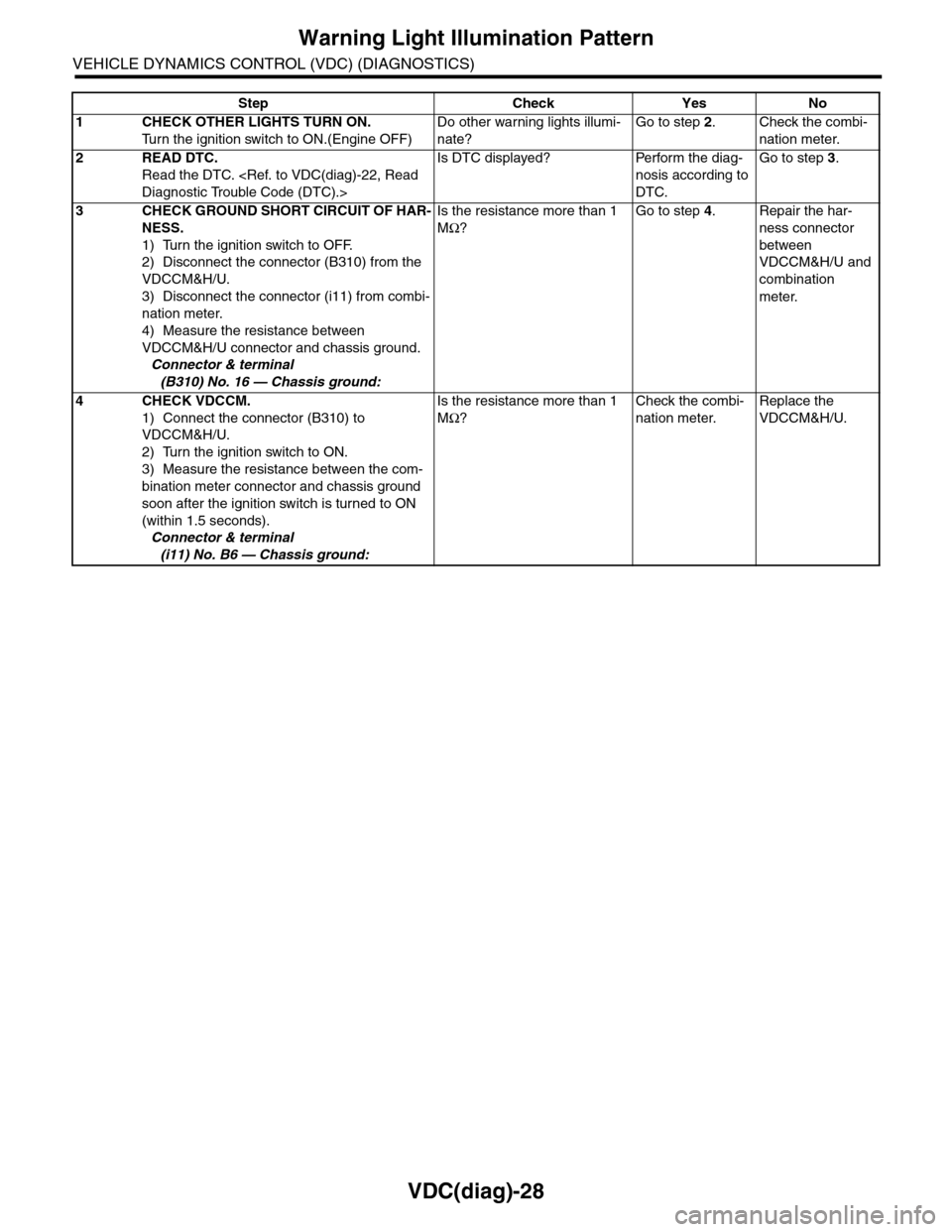
Step Check Yes No
1CHECK OTHER LIGHTS TURN ON.
Tu r n t h e i g n i t i o n s w i t c h t o O N . ( E n g i n e O F F )
Do other warning lights illumi-
nate?
Go to step 2.Check the combi-
nation meter.
2READ DTC.
Read the DTC.
Is DTC displayed? Perform the diag-
nosis according to
DTC.
Go to step 3.
3CHECK GROUND SHORT CIRCUIT OF HAR-
NESS.
1) Turn the ignition switch to OFF.
2) Disconnect the connector (B310) from the
VDCCM&H/U.
3) Disconnect the connector (i11) from combi-
nation meter.
4) Measure the resistance between
VDCCM&H/U connector and chassis ground.
Connector & terminal
(B310) No. 16 — Chassis ground:
Is the resistance more than 1
MΩ?
Go to step 4.Repair the har-
ness connector
between
VDCCM&H/U and
combination
meter.
4CHECK VDCCM.
1) Connect the connector (B310) to
VDCCM&H/U.
2) Turn the ignition switch to ON.
3) Measure the resistance between the com-
bination meter connector and chassis ground
soon after the ignition switch is turned to ON
(within 1.5 seconds).
Connector & terminal
(i11) No. B6 — Chassis ground:
Is the resistance more than 1
MΩ?
Check the combi-
nation meter.
Replace the
VDCCM&H/U.
Page 1021 of 2453
VDC(diag)-29
Warning Light Illumination Pattern
VEHICLE DYNAMICS CONTROL (VDC) (DIAGNOSTICS)
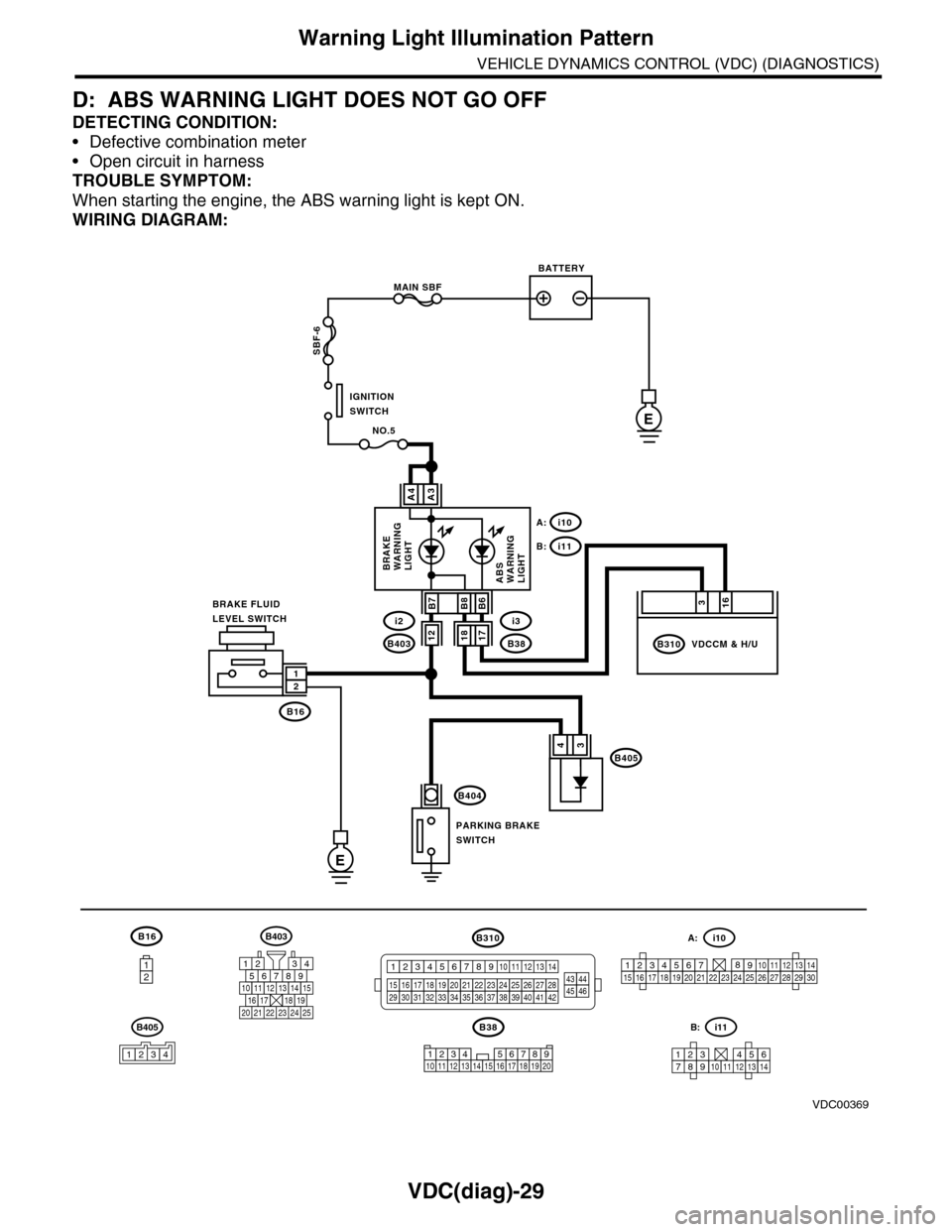
D: ABS WARNING LIGHT DOES NOT GO OFF
DETECTING CONDITION:
•Defective combination meter
•Open circuit in harness
TROUBLE SYMPTOM:
When starting the engine, the ABS warning light is kept ON.
WIRING DIAGRAM:
B16
12
B38
E
MAIN SBF
SBF-6
E
NO.5
B16
B404
A3A4
12
34B405
1234 5678910 11 12 13 14 15 16 17 18 19 20
BATTERY
IGNITIONSWITCH
BRAKE FLUIDLEVEL SWITCH
PARKING BRAKESWITCH
BRAKEWARNINGLIGHTABSWARNINGLIGHT
316
B310B38
i3
i10A:
i11B:
VDCCM & H/U
B8
1817B403
i2B7B6
VDC00369
12
B405
1234
B403
567821943
10
2422 23 25
1112131415161718192021
B310
1234
1516171819202122232425262728293031323334353637383940414245464344568910 11 12 13 147
1234567891011121314
i11B:
123456789101112131415161718192021222324252627282930
i10A:
Page 1022 of 2453
VDC(diag)-30
Warning Light Illumination Pattern
VEHICLE DYNAMICS CONTROL (VDC) (DIAGNOSTICS)
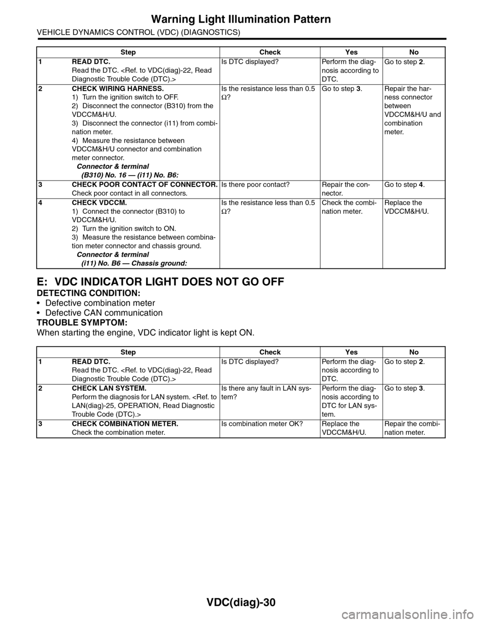
E: VDC INDICATOR LIGHT DOES NOT GO OFF
DETECTING CONDITION:
•Defective combination meter
•Defective CAN communication
TROUBLE SYMPTOM:
When starting the engine, VDC indicator light is kept ON.
Step Check Yes No
1READ DTC.
Read the DTC.
Is DTC displayed? Perform the diag-
nosis according to
DTC.
Go to step 2.
2CHECK WIRING HARNESS.
1) Turn the ignition switch to OFF.
2) Disconnect the connector (B310) from the
VDCCM&H/U.
3) Disconnect the connector (i11) from combi-
nation meter.
4) Measure the resistance between
VDCCM&H/U connector and combination
meter connector.
Connector & terminal
(B310) No. 16 — (i11) No. B6:
Is the resistance less than 0.5
Ω?
Go to step 3.Repair the har-
ness connector
between
VDCCM&H/U and
combination
meter.
3CHECK POOR CONTACT OF CONNECTOR.
Check poor contact in all connectors.
Is there poor contact? Repair the con-
nector.
Go to step 4.
4CHECK VDCCM.
1) Connect the connector (B310) to
VDCCM&H/U.
2) Turn the ignition switch to ON.
3) Measure the resistance between combina-
tion meter connector and chassis ground.
Connector & terminal
(i11) No. B6 — Chassis ground:
Is the resistance less than 0.5
Ω?
Check the combi-
nation meter.
Replace the
VDCCM&H/U.
Step Check Yes No
1READ DTC.
Read the DTC.
Is DTC displayed? Perform the diag-
nosis according to
DTC.
Go to step 2.
2CHECK LAN SYSTEM.
Perfor m the diagnosis for LAN system.
Tr o u b l e C o d e ( D T C ) . >
Is there any fault in LAN sys-
tem?
Pe r for m t h e d ia g -
nosis according to
DTC for LAN sys-
tem.
Go to step 3.
3CHECK COMBINATION METER.
Check the combination meter.
Is combination meter OK? Replace the
VDCCM&H/U.
Repair the combi-
nation meter.
Page 1023 of 2453
VDC(diag)-31
Warning Light Illumination Pattern
VEHICLE DYNAMICS CONTROL (VDC) (DIAGNOSTICS)
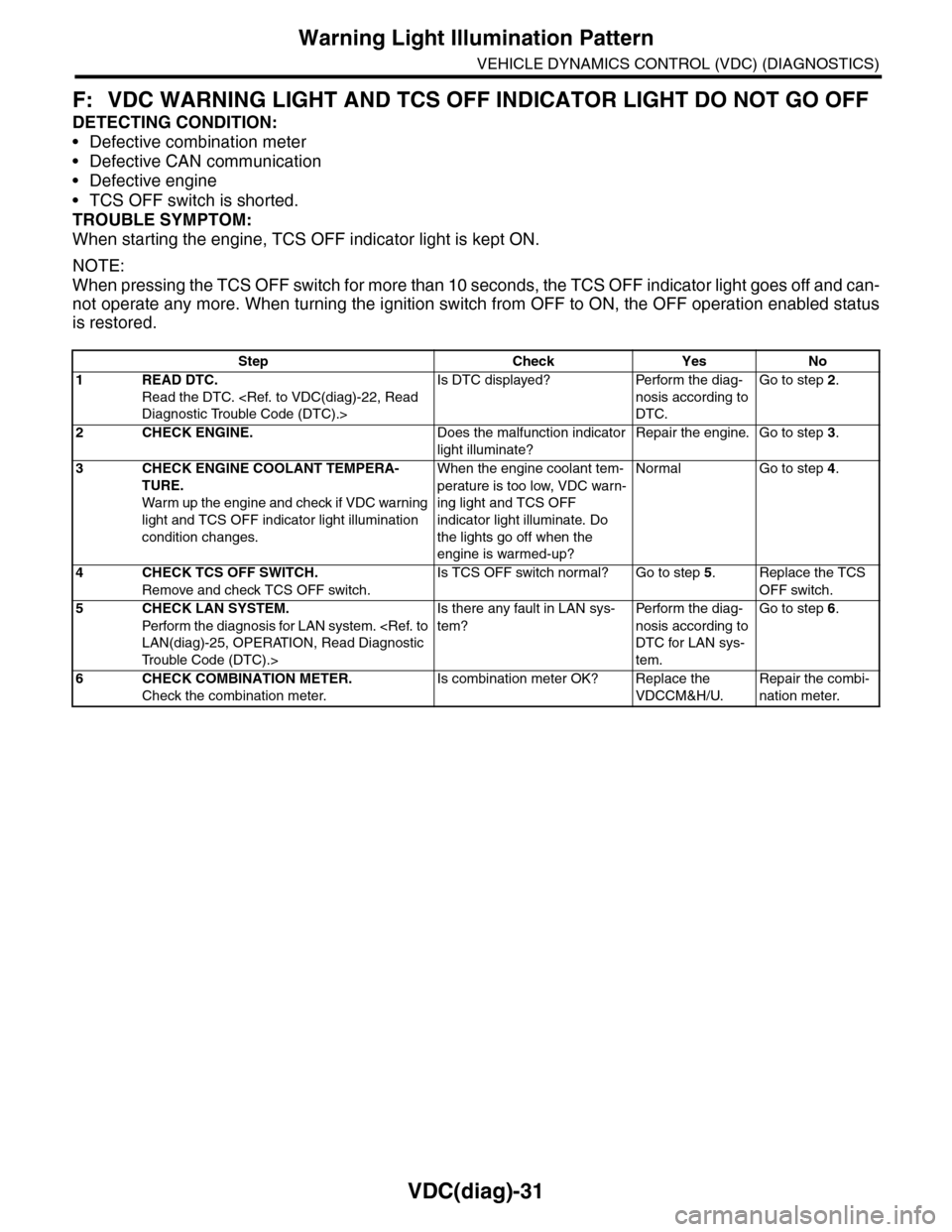
F: VDC WARNING LIGHT AND TCS OFF INDICATOR LIGHT DO NOT GO OFF
DETECTING CONDITION:
•Defective combination meter
•Defective CAN communication
•Defective engine
•TCS OFF switch is shorted.
TROUBLE SYMPTOM:
When starting the engine, TCS OFF indicator light is kept ON.
NOTE:
When pressing the TCS OFF switch for more than 10 seconds, the TCS OFF indicator light goes off and can-
not operate any more. When turning the ignition switch from OFF to ON, the OFF operation enabled status
is restored.
Step Check Yes No
1READ DTC.
Read the DTC.
Is DTC displayed? Perform the diag-
nosis according to
DTC.
Go to step 2.
2CHECK ENGINE.Does the malfunction indicator
light illuminate?
Repair the engine. Go to step 3.
3CHECK ENGINE COOLANT TEMPERA-
TURE.
War m up the engine and check if VDC war ning
light and TCS OFF indicator light illumination
condition changes.
When the engine coolant tem-
perature is too low, VDC warn-
ing light and TCS OFF
indicator light illuminate. Do
the lights go off when the
engine is warmed-up?
Normal Go to step 4.
4CHECK TCS OFF SWITCH.
Remove and check TCS OFF switch.
Is TCS OFF switch normal? Go to step 5.Replace the TCS
OFF switch.
5CHECK LAN SYSTEM.
Perfor m the diagnosis for LAN system.
Tr o u b l e C o d e ( D T C ) . >
Is there any fault in LAN sys-
tem?
Pe r for m t h e d ia g -
nosis according to
DTC for LAN sys-
tem.
Go to step 6.
6CHECK COMBINATION METER.
Check the combination meter.
Is combination meter OK? Replace the
VDCCM&H/U.
Repair the combi-
nation meter.
Page 1025 of 2453
VDC(diag)-33
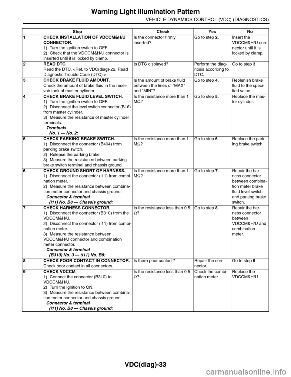
Warning Light Illumination Pattern
VEHICLE DYNAMICS CONTROL (VDC) (DIAGNOSTICS)
Step Check Yes No
1CHECK INSTALLATION OF VDCCM&H/U
CONNECTOR.
1) Turn the ignition switch to OFF.
2) Check that the VDCCM&H/U connector is
inserted until it is locked by clamp.
Is the connector firmly
inserted?
Go to step 2.Insert the
VDCCM&H/U con-
nector until it is
locked by clamp.
2READ DTC.
Read the DTC.
Is DTC displayed? Perform the diag-
nosis according to
DTC.
Go to step 3.
3CHECK BRAKE FLUID AMOUNT.
Check the amount of brake fluid in the reser-
voir tank of master cylinder.
Is the amount of brake fluid
between the lines of “MAX”
and “MIN”?
Go to step 4.Replenish brake
fluid to the speci-
fied value.
4CHECK BRAKE FLUID LEVEL SWITCH.
1) Turn the ignition switch to OFF.
2) Disconnect the level switch connector (B16)
from master cylinder.
3) Measure the resistance of master cylinder
terminals.
Te r m i n a l s
No. 1 — No. 2:
Is the resistance more than 1
MΩ?
Go to step 5.Replace the mas-
ter cylinder.
5CHECK PARKING BRAKE SWITCH.
1) Disconnect the connector (B404) from
parking brake switch.
2) Release the parking brake.
3) Measure the resistance between parking
brake switch terminal and chassis ground.
Is the resistance more than 1
MΩ?
Go to step 6.Replace the park-
ing brake switch.
6CHECK GROUND SHORT OF HARNESS.
1) Disconnect the connector (i11) from combi-
nation meter.
2) Measure the resistance between combina-
tion meter connector and chassis ground.
Connector & terminal
(i11) No. B8 — Chassis ground:
Is the resistance more than 1
MΩ?
Go to step 7.Repair the har-
ness connector
between combina-
tion meter brake
fluid level switch
and parking brake
switch.
7CHECK HARNESS CONNECTOR.
1) Disconnect the connector (B310) from the
VDCCM&H/U.
2) Disconnect the connector (i11) from combi-
nation meter.
3) Measure the resistance between
VDCCM&H/U connector and combination
meter connector.
Connector & terminal
(B310) No. 3 — (i11) No. B8:
Is the resistance less than 0.5
Ω?
Go to step 8.Repair the har-
ness connector
between
VDCCM&H/U and
combination
meter.
8CHECK POOR CONTACT IN CONNECTOR.
Check poor contact in all connectors.
Is there poor contact? Repair the con-
nector.
Go to step 9.
9CHECK VDCCM.
1) Connect the connector (B310) to
VDCCM&H/U.
2) Turn the ignition to ON.
3) Measure the resistance between combina-
tion meter connector and chassis ground.
Connector & terminal
(i11) No. B8 — Chassis ground:
Is the resistance less than 0.5
Ω?
Check the combi-
nation meter.
Replace the
VDCCM&H/U.
Page 1167 of 2453
EN(H6DO)(diag)-6
General Description
ENGINE (DIAGNOSTICS)
C: NOTE
1. GENERAL DESCRIPTION
•The on-board diagnostics (OBD) system detects
and indicates a fault in various inputs and outputs
of the complex electronic control. Malfunction indi-
cator light in the combination meter indicates oc-
currence of a fault or trouble.
•Further, against such a failure or sensors as may
disable the drive, the fail-safe function is provided
to ensure the minimal drivability.
•The OBD system incorporated with the vehicles
within this engine family complies with OBD-II Reg-
ulations. The OBD system monitors the compo-
nents and the system malfunction listed in Engine
Section which affects on emissions.
•When the system decides that a malfunction oc-
curs, malfunction indicator light illuminates. At the
same time of the malfunction indicator light illumi-
nation or blinking, a DTC and a freeze frame en-
gine conditions are stored into on-board computer.
•The OBD system stores freeze frame engine
condition data (engine load, engine coolant tem-
perature, fuel trim, engine speed and vehicle
speed, etc.) into on-board computer when it detects
a malfunction first.
•If the OBD system detects the various malfunc-
tions including the fault of fuel trim or misfire, the
OBD system first stores freeze frame engine condi-
tions about fuel trim or misfire.
•When the malfunction does not occur again for
three consecutive driving cycles, malfunction indi-
cator light is turned off, but DTC remains at on-
board computer.
•When troubleshooting the vehicle which com-
plies with OBD-II Regulations, connect the Subaru
Select Monitor or general scan tool to the vehicle.
2. ENGINE AND EMISSION CONTROL SYS-
TEM
•The Multipoint Fuel Injection (MFI) system is a
system that supplies the optimum air-fuel mixture
to the engine for all the various operating condi-
tions through the use of the latest electronic tech-
nology.
With this system fuel, which is pressurized at a con-
stant pressure, is injected into the intake air pas-
sage of the cylinder head. The injection quantity of
fuel is controlled by an intermittent injection system
where the electro-magnetic injection valve (fuel in-
jector) opens only for a short period of time, de-
pending on the quantity of air required for one cycle
of operation. In actual operation, the injection quan-
tity is determined by the duration of an electric
pulse applied to the fuel injector and this permits
simple, yet highly precise metering of the fuel.
•Further, all the operating conditions of the engine
are converted into electric signals, and this results
in additional features of the system, such as large
improved adaptability, easier addition of compen-
sating element etc.
The MFI system also has the following features:
•Reduced emission of harmful exhaust gases.
•Reduced in fuel consumption.
•Increased engine output.
•Superior acceleration and deceleration.
•Superior startability and warm-up perfor-
mance in cold weather since compensation is
made for coolant and intake air temperature.
Page 1210 of 2453
EN(H6DO)(diag)-49
Malfunction Indicator Light
ENGINE (DIAGNOSTICS)
B: ACTIVATION OF MALFUNCTION
INDICATOR LIGHT
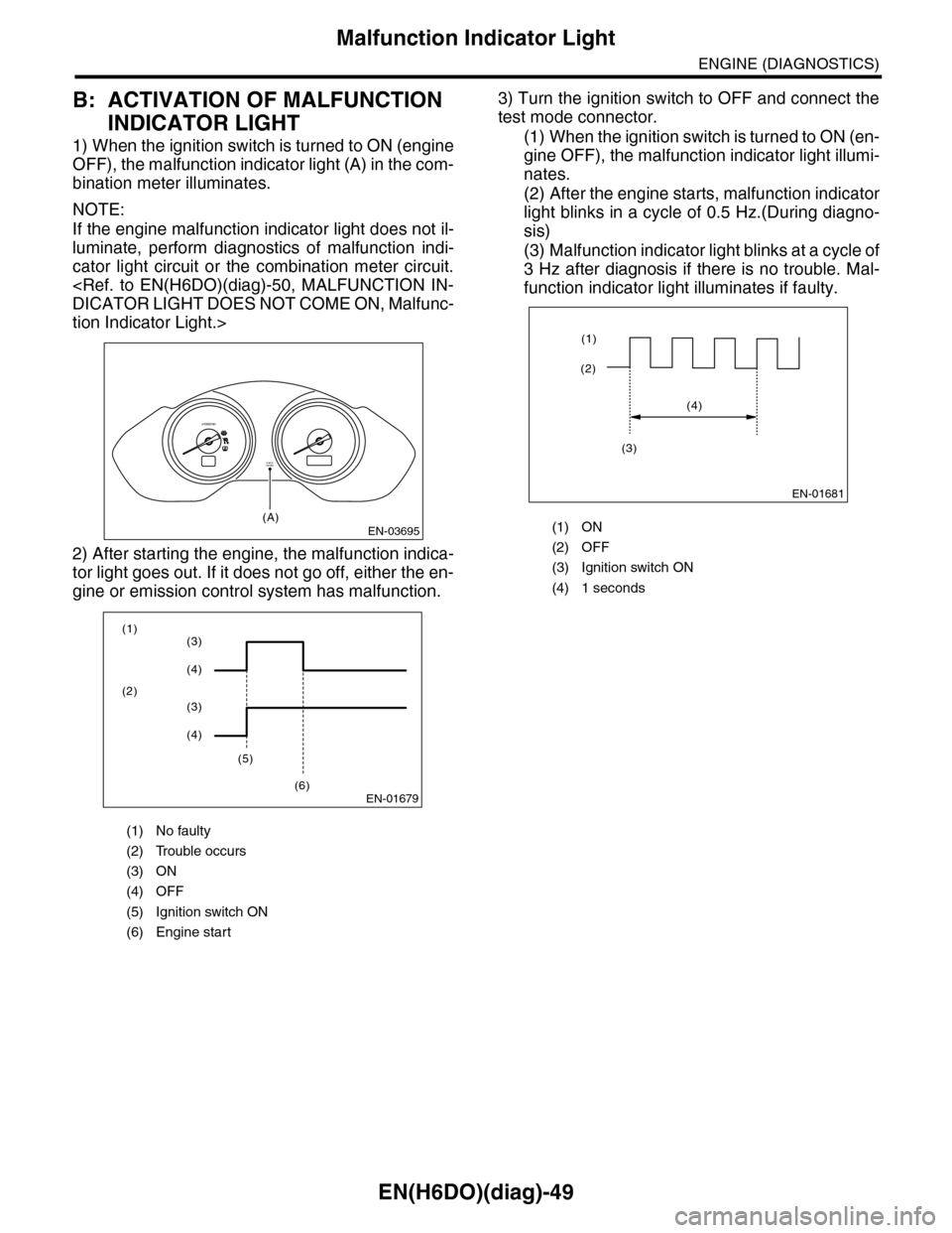
1) When the ignition switch is turned to ON (engine
OFF), the malfunction indicator light (A) in the com-
bination meter illuminates.
NOTE:
If the engine malfunction indicator light does not il-
luminate, perform diagnostics of malfunction indi-
cator light circuit or the combination meter circuit.
tion Indicator Light.>
2) After starting the engine, the malfunction indica-
tor light goes out. If it does not go off, either the en-
gine or emission control system has malfunction.
3) Turn the ignition switch to OFF and connect the
test mode connector.
(1) When the ignition switch is turned to ON (en-
gine OFF), the malfunction indicator light illumi-
nates.
(2) After the engine starts, malfunction indicator
light blinks in a cycle of 0.5 Hz.(During diagno-
sis)
(3) Malfunction indicator light blinks at a cycle of
3 Hz after diagnosis if there is no trouble. Mal-
function indicator light illuminates if faulty.
(1) No faulty
(2) Trouble occurs
(3) ON
(4) OFF
(5) Ignition switch ON
(6) Engine start
EN-03695
CHECKENGINE
(A)
x1000/min
EN-01679
(1)
(2)
(5)
(6)
(3)
(4)
(3)
(4)
(1) ON
(2) OFF
(3) Ignition switch ON
(4) 1 seconds
EN-01681
(2)
(1)
(4)
(3)
Page 1211 of 2453
EN(H6DO)(diag)-50
Malfunction Indicator Light
ENGINE (DIAGNOSTICS)
C: MALFUNCTION INDICATOR LIGHT DOES NOT COME ON
DIAGNOSIS:
The malfunction indicator light circuit is open or shorted.
TROUBLE SYMPTOM:
When the ignition switch is turned to ON (engine OFF), malfunction indicator light does not come on.
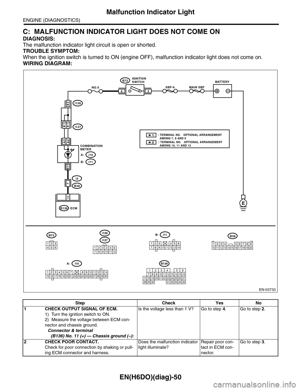
WIRING DIAGRAM:
EN-03733
3
B72
i3
B38
B136
SBF-66
11
A4
7
MAIN SBFNO.5
B11
E
A3
B72
134562
B38
1234 5678910 11 12 13 14 15 16 17 18 19 20
ECM
COMBINATIONMETER
IGNITIONSWITCHBATTERY
i126
i1271*1*
2*
i10A:
i11B:
i127
i126
123456789101112
1234567891011121314
i11B:
123456789101112131415161718192021222324252627282930
i10A:
2* : TERMINAL NO. OPTIONAL ARRANGEMENT AMONG 10, 11 AND 12
1* : TERMINAL NO. OPTIONAL ARRANGEMENT AMONG 7, 8 AND 9
B136
16101112131415252430
9871718192028212223293231
123456
2726333435
Step Check Yes No
1CHECK OUTPUT SIGNAL OF ECM.
1) Turn the ignition switch to ON.
2) Measure the voltage between ECM con-
nector and chassis ground.
Connector & terminal
(B136) No. 11 (+) — Chassis ground (–):
Is the voltage less than 1 V? Go to step 4.Go to step 2.
2CHECK POOR CONTACT.
Check for poor connection by shaking or pull-
ing ECM connector and harness.
Does the malfunction indicator
light illuminate?
Repair poor con-
tact in ECM con-
nector.
Go to step 3.