2009 SUBARU TRIBECA check engine light
[x] Cancel search: check engine lightPage 1926 of 2453
ME(H6DO)-60
Cylinder Head
MECHANICAL
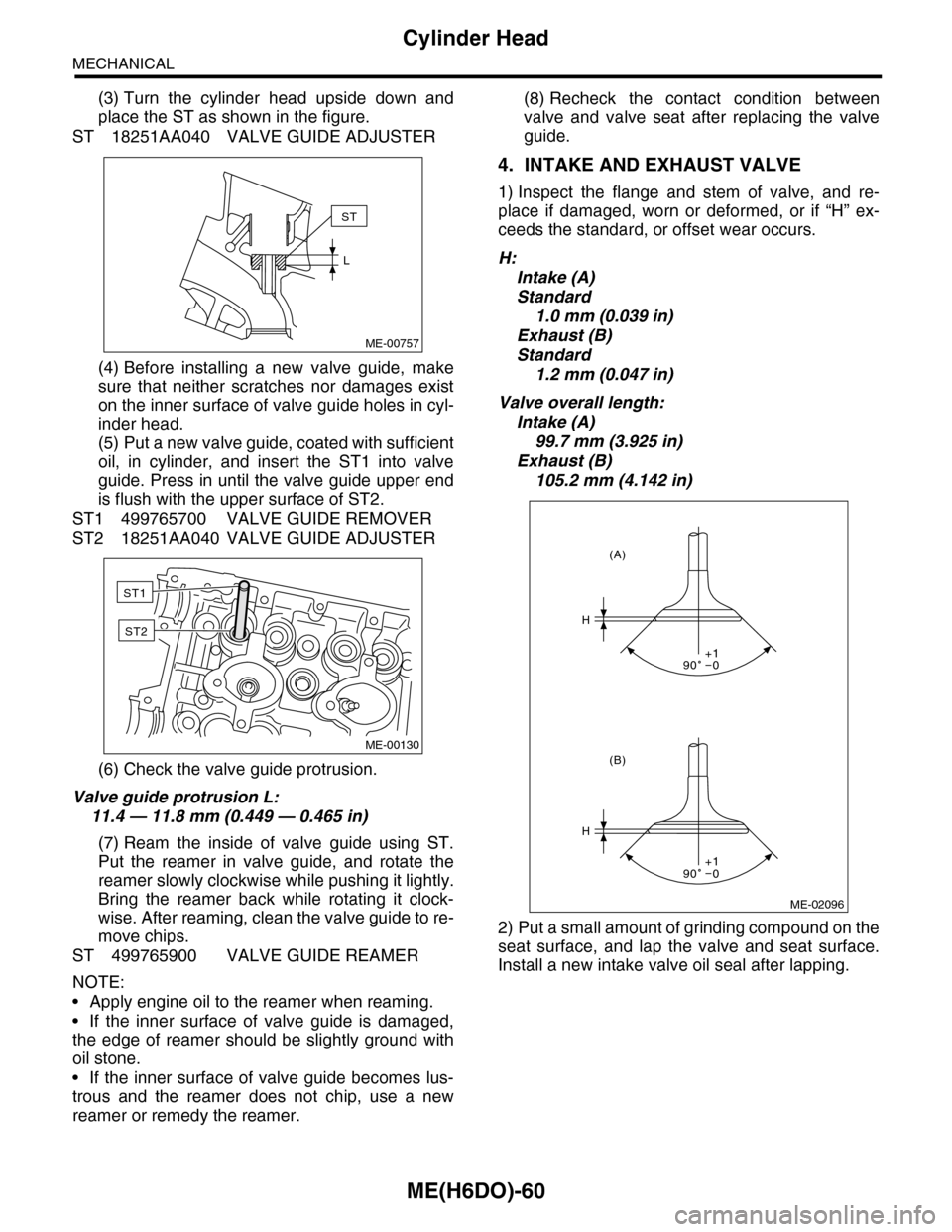
(3) Turn the cylinder head upside down and
place the ST as shown in the figure.
ST 18251AA040 VALVE GUIDE ADJUSTER
(4) Before installing a new valve guide, make
sure that neither scratches nor damages exist
on the inner surface of valve guide holes in cyl-
inder head.
(5) Put a new valve guide, coated with sufficient
oil, in cylinder, and insert the ST1 into valve
guide. Press in until the valve guide upper end
is flush with the upper surface of ST2.
ST1 499765700 VALVE GUIDE REMOVER
ST2 18251AA040 VALVE GUIDE ADJUSTER
(6) Check the valve guide protrusion.
Valve guide protrusion L:
11.4 — 11.8 mm (0.449 — 0.465 in)
(7) Ream the inside of valve guide using ST.
Put the reamer in valve guide, and rotate the
reamer slowly clockwise while pushing it lightly.
Bring the reamer back while rotating it clock-
wise. After reaming, clean the valve guide to re-
move chips.
ST 499765900 VALVE GUIDE REAMER
NOTE:
•Apply engine oil to the reamer when reaming.
•If the inner surface of valve guide is damaged,
the edge of reamer should be slightly ground with
oil stone.
•If the inner surface of valve guide becomes lus-
trous and the reamer does not chip, use a new
reamer or remedy the reamer.
(8) Recheck the contact condition between
valve and valve seat after replacing the valve
guide.
4. INTAKE AND EXHAUST VALVE
1) Inspect the flange and stem of valve, and re-
place if damaged, worn or deformed, or if “H” ex-
ceeds the standard, or offset wear occurs.
H:
Intake (A)
Standard
1.0 mm (0.039 in)
Exhaust (B)
Standard
1.2 mm (0.047 in)
Valve overall length:
Intake (A)
99.7 mm (3.925 in)
Exhaust (B)
105.2 mm (4.142 in)
2) Put a small amount of grinding compound on the
seat surface, and lap the valve and seat surface.
Install a new intake valve oil seal after lapping.
ME-00757
ST
L
ME-00130
ST1
ST2
ME-02096
H
H
(B)
(A)
90 0+1
90 0+1
Page 2002 of 2453
PM-19
Brake Line
PERIODIC MAINTENANCE SERVICES
13.Brake Line
A: INSPECTION
1. BRAKE LINE
1) Check for scratches, swelling, corrosion, traces
of fluid leakage on the brake hoses or pipe joints.
2) Check the possibility of adjacent parts interfering
with brake pipes/hoses during driving, and loose
connections/clamps.
3) Check any trace of fluid leakage, scratches, etc.
on master cylinder, wheel cylinder and pressure
control valve.
NOTE:
•When the brake fluid level in the reservoir tank is
lower than specified limit, the brake warning light
on the combination meter will come on.
•Visually check the brake hose for damage. (Use
a mirror where it is difficult to see)
2. SERVICE BRAKE
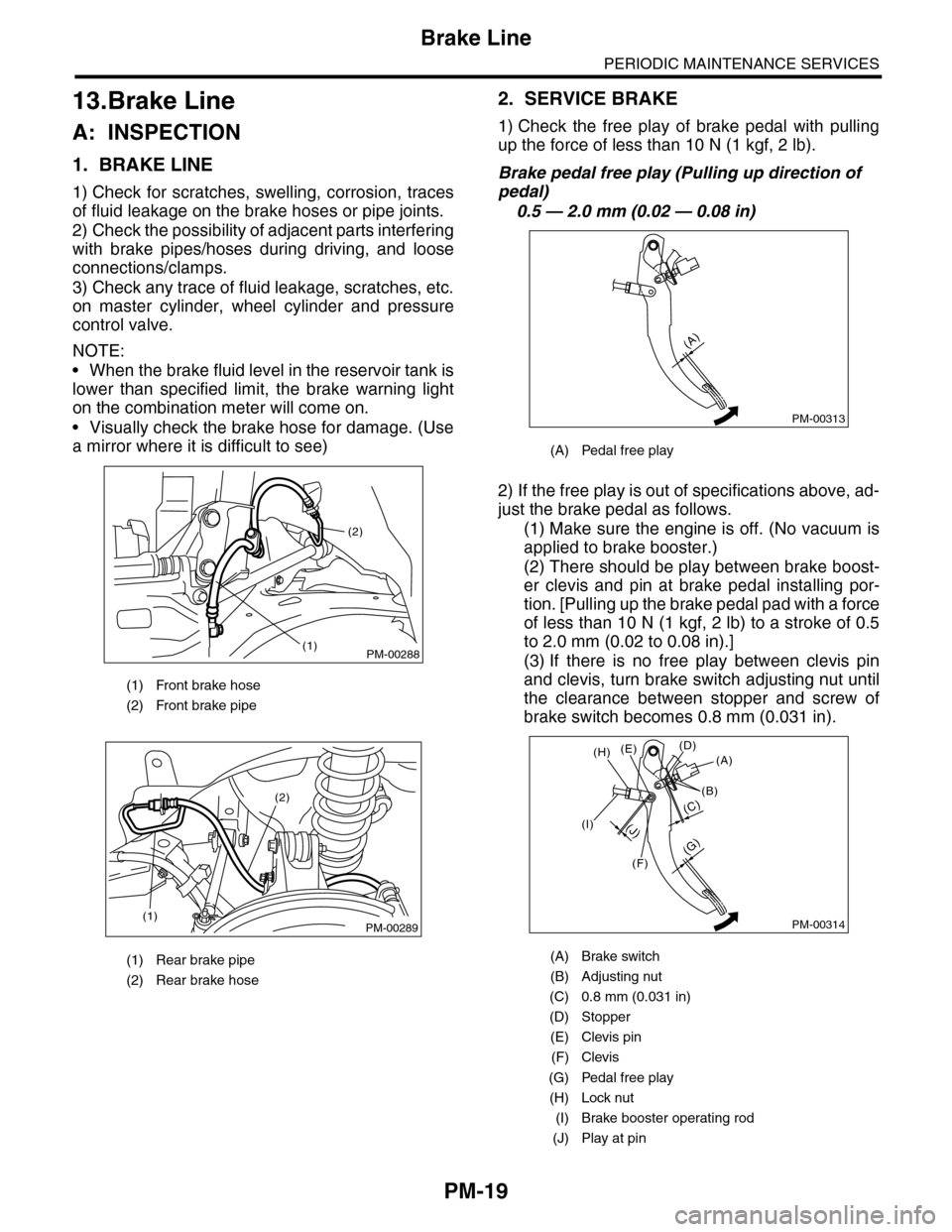
1) Check the free play of brake pedal with pulling
up the force of less than 10 N (1 kgf, 2 lb).
Brake pedal free play (Pulling up direction of
pedal)
0.5 — 2.0 mm (0.02 — 0.08 in)
2) If the free play is out of specifications above, ad-
just the brake pedal as follows.
(1) Make sure the engine is off. (No vacuum is
applied to brake booster.)
(2) There should be play between brake boost-
er clevis and pin at brake pedal installing por-
tion. [Pulling up the brake pedal pad with a force
of less than 10 N (1 kgf, 2 lb) to a stroke of 0.5
to 2.0 mm (0.02 to 0.08 in).]
(3) If there is no free play between clevis pin
and clevis, turn brake switch adjusting nut until
the clearance between stopper and screw of
brake switch becomes 0.8 mm (0.031 in).
(1) Front brake hose
(2) Front brake pipe
(1) Rear brake pipe
(2) Rear brake hose
PM-00288
(2)
(1)
PM-00289(1)
(2)
(A) Pedal free play
(A) Brake switch
(B) Adjusting nut
(C) 0.8 mm (0.031 in)
(D) Stopper
(E) Clevis pin
(F) Clevis
(G) Pedal free play
(H) Lock nut
(I) Brake booster operating rod
(J) Play at pin
PM-00313
(A)
PM-00314
(G)
(A)(D)(E)
(B)
(C)
(F)
(J)(I)
(H)
Page 2003 of 2453
PM-20
Brake Line
PERIODIC MAINTENANCE SERVICES
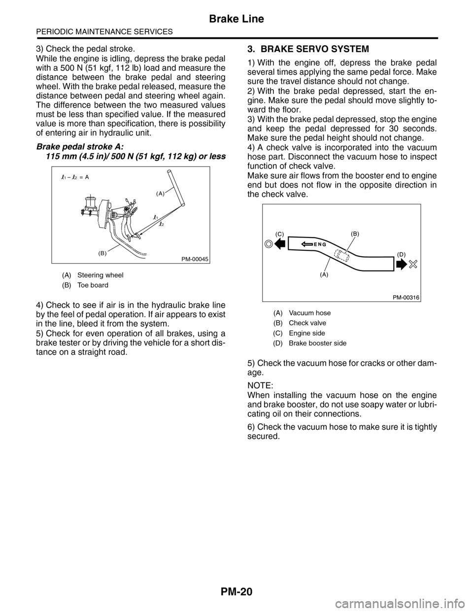
3) Check the pedal stroke.
While the engine is idling, depress the brake pedal
with a 500 N (51 kgf, 112 lb) load and measure the
distance between the brake pedal and steering
wheel. With the brake pedal released, measure the
distance between pedal and steering wheel again.
The difference between the two measured values
must be less than specified value. If the measured
value is more than specification, there is possibility
of entering air in hydraulic unit.
Brake pedal stroke A:
115 mm (4.5 in)/ 500 N (51 kgf, 112 kg) or less
4) Check to see if air is in the hydraulic brake line
by the feel of pedal operation. If air appears to exist
in the line, bleed it from the system.
5) Check for even operation of all brakes, using a
brake tester or by driving the vehicle for a short dis-
tance on a straight road.
3. BRAKE SERVO SYSTEM
1) With the engine off, depress the brake pedal
several times applying the same pedal force. Make
sure the travel distance should not change.
2) With the brake pedal depressed, start the en-
gine. Make sure the pedal should move slightly to-
ward the floor.
3) With the brake pedal depressed, stop the engine
and keep the pedal depressed for 30 seconds.
Make sure the pedal height should not change.
4) A check valve is incorporated into the vacuum
hose part. Disconnect the vacuum hose to inspect
function of check valve.
Make sure air flows from the booster end to engine
end but does not flow in the opposite direction in
the check valve.
5) Check the vacuum hose for cracks or other dam-
age.
NOTE:
When installing the vacuum hose on the engine
and brake booster, do not use soapy water or lubri-
cating oil on their connections.
6) Check the vacuum hose to make sure it is tightly
secured.
(A) Steering wheel
(B) Toe board
PM-00045(B)
(A)
= A
1
12
2
(A) Vacuum hose
(B) Check valve
(C) Engine side
(D) Brake booster side
Page 2138 of 2453
5AT(diag)-21
Learning Control
AUTOMATIC TRANSMISSION (DIAGNOSTICS)
10.Learning Control
A: GENERAL DESCRIPTION
Be sure to perform the {Clear Memory 2} only when
the following services have been performed. And
when the shifting shock is occurred during the total
check with vehicle driving, perform the learning
with following procedures.
Select Monitor.>
•Replacement of TCM
•Replacement of transmission assembly
•Simultaneous replacement of TCM and trans-
mission assembly
•Replacement of each clutch
•Replacement of control valve body
CAUTION:
When {Clear Memory 2} is executed, DTC may
not be cleared.
B: PROCEDURE
1) Turn the ignition switch to ON.
2) Turn the air conditioner switch to OFF.
3) Turn the headlight switch to OFF.
4) Turn the rear defogger switch to OFF.
5) Start the engine.
6) Connect the Subaru Select Monitor to the vehi-
cle.
7) Drive the vehicle for 5 — 10 km (3 — 6 mile) to
warm up ATF temperature more than 70 °C (158
°F).
8) While checking that the throttle opening angle on
Subaru Select Monitor is within the specified range,
shift the gear from 1st → 2nd, 2nd → 3rd, and 3rd
→ 4th, while driving the vehicle at “D” range.
ATION, Subaru Select Monitor.>
Acceleration opening angle:
12.5%±2%
9) While checking that the throttle opening angle on
Subaru Select Monitor is within the specified range,
upshift the gear from 4th → 5 t h w h i l e d r i v i n g t h e v e -
hicle at “D” range.
Acceleration opening angle:
15.5%±2%
10) Repeat the steps 8) and 9) until the reducing ef-
fect of the shifting shock is felt.
11) If reducing of shifting shock is not felt after 5 cy-
cles, recheck that the learning conditions (throttle
opening angle, ATF temperature, etc.) are as spec-
ified and recheck that other parts are normal.
Page 2139 of 2453
5AT(diag)-22
SPORT Indicator Light Display
AUTOMATIC TRANSMISSION (DIAGNOSTICS)
11.SPORT Indicator Light Display
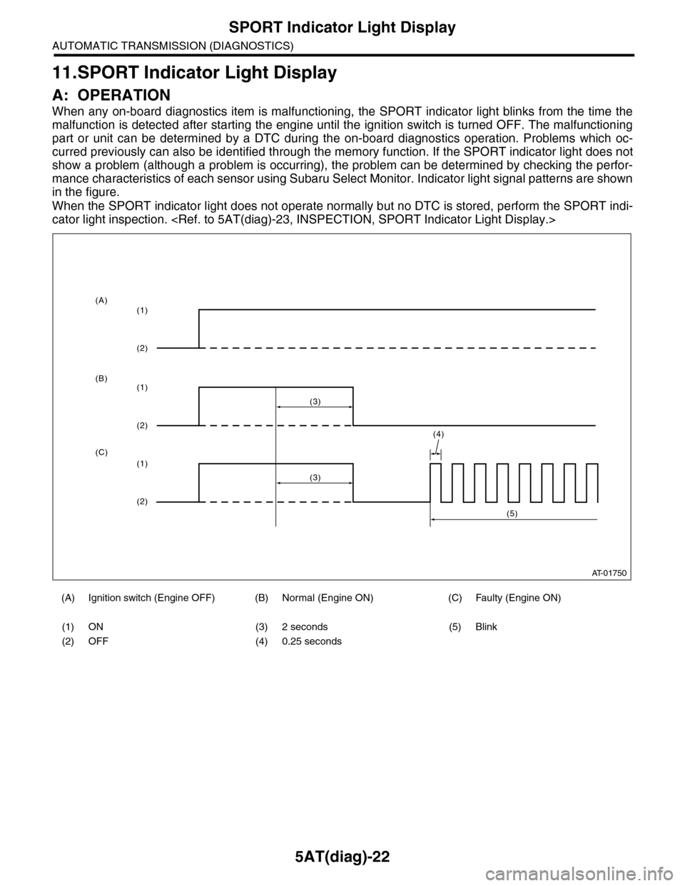
A: OPERATION
When any on-board diagnostics item is malfunctioning, the SPORT indicator light blinks from the time the
malfunction is detected after starting the engine until the ignition switch is turned OFF. The malfunctioning
part or unit can be determined by a DTC during the on-board diagnostics operation. Problems which oc-
curred previously can also be identified through the memory function. If the SPORT indicator light does not
show a problem (although a problem is occurring), the problem can be determined by checking the perfor-
mance characteristics of each sensor using Subaru Select Monitor. Indicator light signal patterns are shown
in the figure.
When the SPORT indicator light does not operate normally but no DTC is stored, perform the SPORT indi-
cator light inspection.
(A) Ignition switch (Engine OFF) (B) Normal (Engine ON) (C) Faulty (Engine ON)
(1) ON (3) 2 seconds (5) Blink
(2) OFF (4) 0.25 seconds
AT-01750
(4)
(3)
(1)
(2)
(1)
(2)
(1)
(2)
(3)
(5)
(A)
(B)
(C)
Page 2141 of 2453
5AT(diag)-24
SPORT Indicator Light Display
AUTOMATIC TRANSMISSION (DIAGNOSTICS)
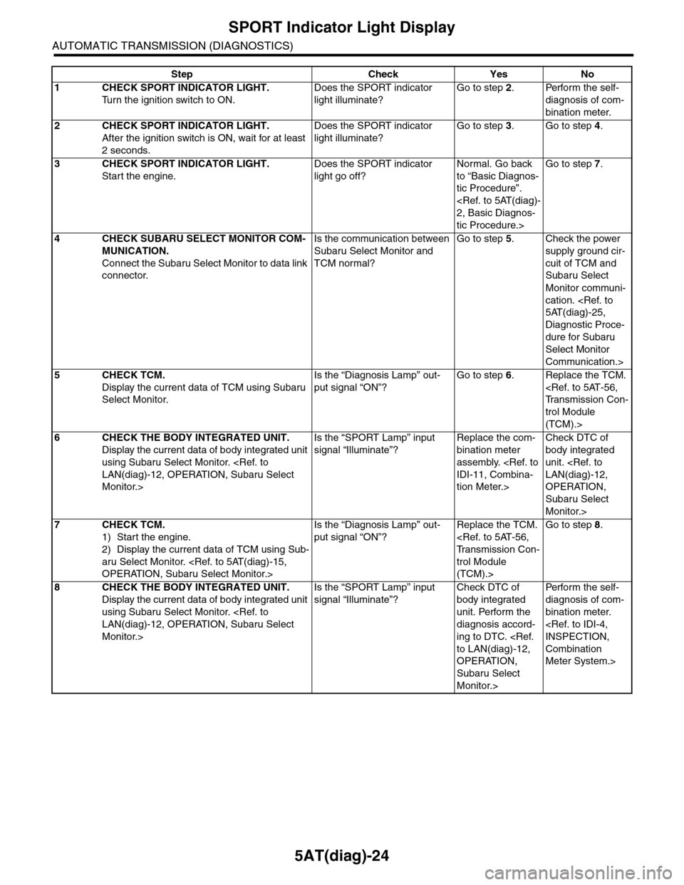
Step Check Yes No
1CHECK SPORT INDICATOR LIGHT.
Tu r n t h e i g n i t i o n s w i t c h t o O N .
Does the SPORT indicator
light illuminate?
Go to step 2.Perform the self-
diagnosis of com-
bination meter.
2CHECK SPORT INDICATOR LIGHT.
After the ignition switch is ON, wait for at least
2 seconds.
Does the SPORT indicator
light illuminate?
Go to step 3.Go to step 4.
3CHECK SPORT INDICATOR LIGHT.
Start the engine.
Does the SPORT indicator
light go off?
Normal. Go back
to “Basic Diagnos-
tic Procedure”.
tic Procedure.>
Go to step 7.
4CHECK SUBARU SELECT MONITOR COM-
MUNICATION.
Connect the Subaru Select Monitor to data link
connector.
Is the communication between
Subaru Select Monitor and
TCM normal?
Go to step 5.Check the power
supply ground cir-
cuit of TCM and
Subaru Select
Monitor communi-
cation.
Diagnostic Proce-
dure for Subaru
Select Monitor
Communication.>
5CHECK TCM.
Display the current data of TCM using Subaru
Select Monitor.
Is the “Diagnosis Lamp” out-
put signal “ON”?
Go to step 6.Replace the TCM.
trol Module
(TCM).>
6CHECK THE BODY INTEGRATED UNIT.
Display the current data of body integrated unit
using Subaru Select Monitor.
Monitor.>
Is the “SPORT Lamp” input
signal “Illuminate”?
Replace the com-
bination meter
assembly.
tion Meter.>
Check DTC of
body integrated
unit.
OPERATION,
Subaru Select
Monitor.>
7CHECK TCM.
1) Start the engine.
2) Display the current data of TCM using Sub-
aru Select Monitor.
Is the “Diagnosis Lamp” out-
put signal “ON”?
Replace the TCM.
trol Module
(TCM).>
Go to step 8.
8CHECK THE BODY INTEGRATED UNIT.
Display the current data of body integrated unit
using Subaru Select Monitor.
Monitor.>
Is the “SPORT Lamp” input
signal “Illuminate”?
Check DTC of
body integrated
unit. Perform the
diagnosis accord-
ing to DTC.
OPERATION,
Subaru Select
Monitor.>
Per fo r m th e se lf -
diagnosis of com-
bination meter.
Combination
Meter System.>
Page 2153 of 2453
5AT(diag)-36
Diagnostic Procedure with Diagnostic Trouble Code (DTC)
AUTOMATIC TRANSMISSION (DIAGNOSTICS)
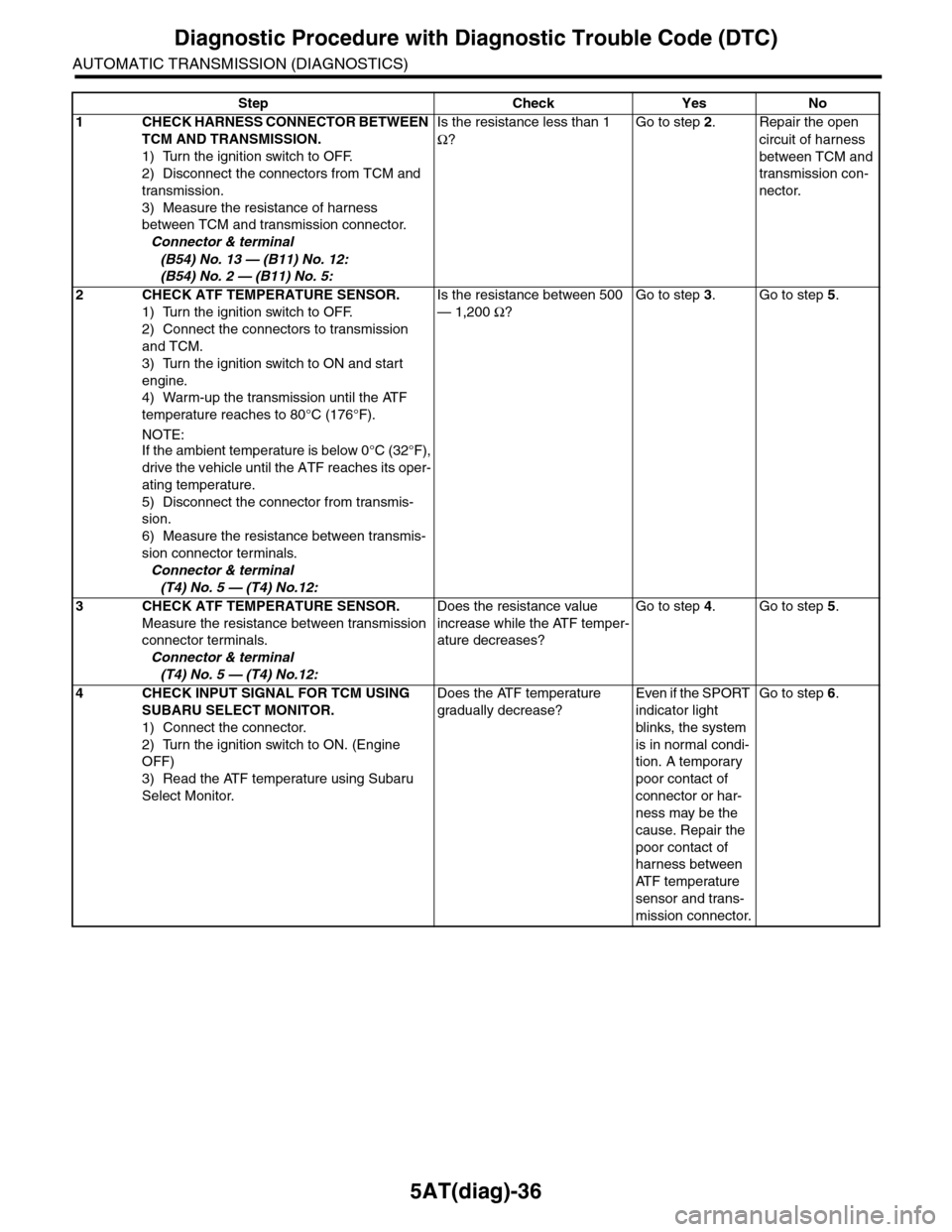
Step Check Yes No
1CHECK HARNESS CONNECTOR BETWEEN
TCM AND TRANSMISSION.
1) Turn the ignition switch to OFF.
2) Disconnect the connectors from TCM and
transmission.
3) Measure the resistance of harness
between TCM and transmission connector.
Connector & terminal
(B54) No. 13 — (B11) No. 12:
(B54) No. 2 — (B11) No. 5:
Is the resistance less than 1
Ω?
Go to step 2.Repair the open
circuit of harness
between TCM and
transmission con-
nector.
2CHECK ATF TEMPERATURE SENSOR.
1) Turn the ignition switch to OFF.
2) Connect the connectors to transmission
and TCM.
3) Turn the ignition switch to ON and start
engine.
4) Warm-up the transmission until the ATF
temperature reaches to 80°C (176°F).
NOTE:
If the ambient temperature is below 0°C (32°F),
drive the vehicle until the ATF reaches its oper-
ating temperature.
5) Disconnect the connector from transmis-
sion.
6) Measure the resistance between transmis-
sion connector terminals.
Connector & terminal
(T4) No. 5 — (T4) No.12:
Is the resistance between 500
— 1,200 Ω?
Go to step 3.Go to step 5.
3CHECK ATF TEMPERATURE SENSOR.
Measure the resistance between transmission
connector terminals.
Connector & terminal
(T4) No. 5 — (T4) No.12:
Does the resistance value
increase while the ATF temper-
ature decreases?
Go to step 4.Go to step 5.
4CHECK INPUT SIGNAL FOR TCM USING
SUBARU SELECT MONITOR.
1) Connect the connector.
2) Turn the ignition switch to ON. (Engine
OFF)
3) Read the ATF temperature using Subaru
Select Monitor.
Does the ATF temperature
gradually decrease?
Even if the SPORT
indicator light
blinks, the system
is in normal condi-
tion. A temporary
poor contact of
connector or har-
ness may be the
cause. Repair the
poor contact of
harness between
AT F t e m p e r a t u r e
sensor and trans-
mission connector.
Go to step 6.
Page 2156 of 2453
5AT(diag)-39
Diagnostic Procedure with Diagnostic Trouble Code (DTC)
AUTOMATIC TRANSMISSION (DIAGNOSTICS)
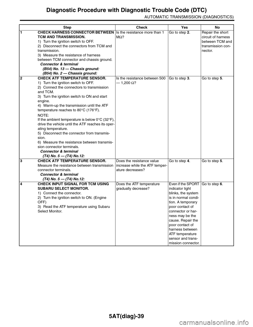
Step Check Yes No
1CHECK HARNESS CONNECTOR BETWEEN
TCM AND TRANSMISSION.
1) Turn the ignition switch to OFF.
2) Disconnect the connectors from TCM and
transmission.
3) Measure the resistance of harness
between TCM connector and chassis ground.
Connector & terminal
(B54) No. 13 — Chassis ground:
(B54) No. 2 — Chassis ground:
Is the resistance more than 1
MΩ?
Go to step 2.Repair the short
circuit of harness
between TCM and
transmission con-
nector.
2CHECK ATF TEMPERATURE SENSOR.
1) Turn the ignition switch to OFF.
2) Connect the connectors to transmission
and TCM.
3) Turn the ignition switch to ON and start
engine.
4) Warm-up the transmission until the ATF
temperature reaches to 80°C (176°F).
NOTE:
If the ambient temperature is below 0°C (32°F),
drive the vehicle until the ATF reaches its oper-
ating temperature.
5) Disconnect the connector from transmis-
sion.
6) Measure the resistance between transmis-
sion connector terminals.
Connector & terminal
(T4) No. 5 — (T4) No.12:
Is the resistance between 500
— 1,200 Ω?
Go to step 3.Go to step 5.
3CHECK ATF TEMPERATURE SENSOR.
Measure the resistance between transmission
connector terminals.
Connector & terminal
(T4) No. 5 — (T4) No.12:
Does the resistance value
increase while the ATF temper-
ature decreases?
Go to step 4.Go to step 5.
4CHECK INPUT SIGNAL FOR TCM USING
SUBARU SELECT MONITOR.
1) Connect the connector.
2) Turn the ignition switch to ON. (Engine
OFF)
3) Read the ATF temperature using Subaru
Select Monitor.
Does the ATF temperature
gradually decrease?
Even if the SPORT
indicator light
blinks, the system
is in normal condi-
tion. A temporary
poor contact of
connector or har-
ness may be the
cause. Repair the
poor contact of
harness between
AT F t e m p e r a t u r e
sensor and trans-
mission connector.
Go to step 6.