2009 SUBARU TRIBECA check engine light
[x] Cancel search: check engine lightPage 1169 of 2453
EN(H6DO)(diag)-8
Electrical Component Location
ENGINE (DIAGNOSTICS)
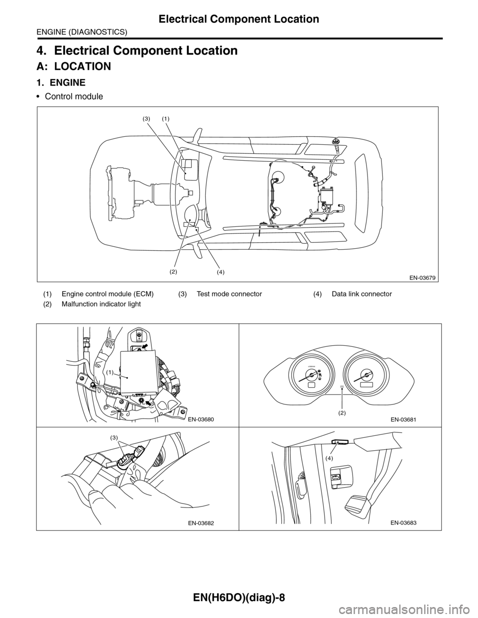
4. Electrical Component Location
A: LOCATION
1. ENGINE
•Control module
(1) Engine control module (ECM) (3) Test mode connector (4) Data link connector
(2) Malfunction indicator light
EN-03679
(1)
(4)
(3)
(2)
EN-03680
(1)
EN-03681
CHECKENGINE
(2)
x1000/min
EN-03682
(3)
EN-03683
(4)
Page 1184 of 2453
EN(H6DO)(diag)-23
General Scan Tool
ENGINE (DIAGNOSTICS)
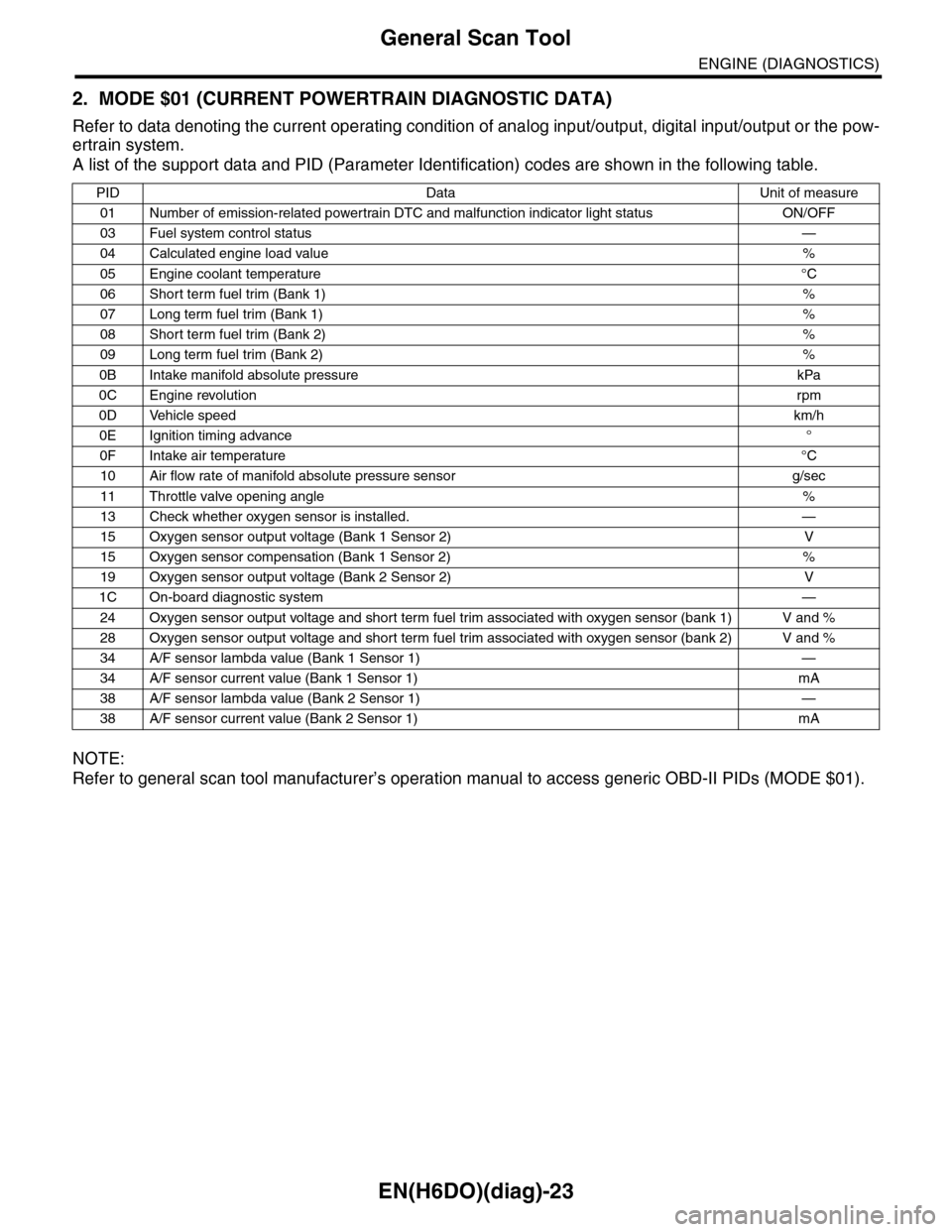
2. MODE $01 (CURRENT POWERTRAIN DIAGNOSTIC DATA)
Refer to data denoting the current operating condition of analog input/output, digital input/output or the pow-
ertrain system.
A list of the support data and PID (Parameter Identification) codes are shown in the following table.
NOTE:
Refer to general scan tool manufacturer’s operation manual to access generic OBD-II PIDs (MODE $01).
PID Data Unit of measure
01 Number of emission-related powertrain DTC and malfunction indicator light status ON/OFF
03 Fuel system control status—
04 Calculated engine load value%
05 Engine coolant temperature°C
06 Short term fuel trim (Bank 1)%
07 Long term fuel trim (Bank 1)%
08 Short term fuel trim (Bank 2)%
09 Long term fuel trim (Bank 2)%
0B Intake manifold absolute pressure kPa
0C Engine revolutionrpm
0D Vehicle speedkm/h
0E Ignition timing advance°
0F Intake air temperature°C
10 Air flow rate of manifold absolute pressure sensor g/sec
11 Throttle valve opening angle%
13 Check whether oxygen sensor is installed. —
15 Oxygen sensor output voltage (Bank 1 Sensor 2) V
15 Oxygen sensor compensation (Bank 1 Sensor 2) %
19 Oxygen sensor output voltage (Bank 2 Sensor 2) V
1C On-board diagnostic system—
24 Oxygen sensor output voltage and short term fuel trim associated with oxygen sensor (bank 1) V and %
28 Oxygen sensor output voltage and short term fuel trim associated with oxygen sensor (bank 2) V and %
34 A/F sensor lambda value (Bank 1 Sensor 1) —
34 A/F sensor current value (Bank 1 Sensor 1) mA
38 A/F sensor lambda value (Bank 2 Sensor 1) —
38 A/F sensor current value (Bank 2 Sensor 1) mA
Page 1190 of 2453
![SUBARU TRIBECA 2009 1.G Service Workshop Manual EN(H6DO)(diag)-29
Subaru Select Monitor
ENGINE (DIAGNOSTICS)
5. READ CURRENT DATA FOR ENGINE (OBD MODE)
1) On the «Main Menu» display screen, select the {Each System Check} and press the [YES] key.
SUBARU TRIBECA 2009 1.G Service Workshop Manual EN(H6DO)(diag)-29
Subaru Select Monitor
ENGINE (DIAGNOSTICS)
5. READ CURRENT DATA FOR ENGINE (OBD MODE)
1) On the «Main Menu» display screen, select the {Each System Check} and press the [YES] key.](/manual-img/17/7322/w960_7322-1189.png)
EN(H6DO)(diag)-29
Subaru Select Monitor
ENGINE (DIAGNOSTICS)
5. READ CURRENT DATA FOR ENGINE (OBD MODE)
1) On the «Main Menu» display screen, select the {Each System Check} and press the [YES] key.
2) On the «System Selection Menu» display screen, select the {Engine} and press the [YES] key.
3) Press the [YES] key after the information of engine type has been displayed.
4) On the «Engine Diagnosis» display screen, select the {OBD System} and press the [YES] key.
5) On the «OBD Menu» display screen, select the {Current Data Display/Save}, and then press the [YES]
key.
6) On the «Data Display Menu» screen, select the {Data Display} and press the [YES] key.
7) Using the scroll key, scroll the display screen up or down until the desired data is shown.
•A list of the support data is shown in the following table.
AT c o o r d i n a t e f u e l c u t d e m a n d s i g n a l AT c o o r d i n a t e f u e l c u t d e m a n d — O F F
Ve h i c l e d y n a m i c s c o n t r o l ( V D C ) t o r q u e d o w n
prohibition outputBan of Torque Down — Permission
Ve h i c l e d y n a m i c s c o n t r o l ( V D C ) t o r q u e d o w n
demandVDC torque down demand — OFF
AT c o o r d i n a t e p e r m i s s i o n s i g n a l AT c o o r d i n a t e p e r m i s s i o n s i g n a l — P e r m i s s i o n
Electronic throttle control motor relay signal ETC motor relay — ON
Stop light switch signal Stop Light Switch — OFF
SET/COAST switch signal SET/COAST SW — OFF
RESUME/ACCEL switch signal RESUME/ACCEL SW — OFF
Brake switch signal Brake SW — OFF
Main switch signal Main SW — OFF
Body integrated unit data reception Body Int. Unit Data — Yes
Body integlated unit counter update Body Int. Unit Count — Yes
Cruise control cancel switch signal CC Cancel SW — OFF
Va r i a b l e v a l v e l i f t d i a g n o s i s o i l p r e s s u r e sw i t c h
signal 1Oil Temperature SW1 — ON
Va r i a b l e v a l v e l i f t d i a g n o s i s o i l p r e s s u r e sw i t c h
signal 2Oil Temperature SW2 — ON
Description Display Unit of measure
Number of diagnosis code Number of Diag. Codes: 0
Condition of malfunction indicator light MI (MIL) ON or OFF
Monitoring test of misfire Misfire monitoring Finish
Monitoring test of fuel system Fuel system monitoring Finish
Monitoring test of comprehensive component Component monitoring Finish
Te s t o f c a t a l y s t C a t a l y s t D i a g n o s i s F i n i s h o r i n c o m p l e t e
Te s t o f h e a t i n g - t y p e c a t a l y s t H e a t e d c a t a l y s t N o
Te s t o f e v a p o r a t i v e e m i s s i o n p u r g e c o n t r o l s y s t e m E v a p o r a t i v e p u r g e s y s t e m F i n i s h o r i n c o m p l e t e
Te s t o f s e c o n d a r y a i r s y s t e m S e c o n d a r y a i r s y s t e m N o
Te s t o f a i r c o n d i t i o n i n g s y s t e m r e f r i g e r a n t A / C s y s t e m r e f r i g e r a n t N o
Te s t o f o x y g e n s e n s o r O x y g e n s e n o r F i n i s h o r i n c o m p l e t e
Te s t o f o x y g e n s e n s o r h e a t e r O x y g e n s e n s o r h e a t e r F i n i s h
Te s t o f E G R s y s t e m E G R s y s t e m N o s u p p o r t
A/F control #1 Fuel system for Bank 1 OPEN early period
A/F control #2 Fuel system for Bank 2 OPEN early period
Calculated load valve Calculated load valve %
Engine coolant temperature Coolant Temp. °C
A/F compensation #1 Short term fuel trim B1 %
A/F learning #1 Long term fuel trim B1 %
A/F compensation #2 Short term fuel trim #2 %
A/F learning #2 Long term fuel trim B2 %
Description Display Unit of measure Note (at idling)
Page 1193 of 2453
![SUBARU TRIBECA 2009 1.G Service Workshop Manual EN(H6DO)(diag)-32
Subaru Select Monitor
ENGINE (DIAGNOSTICS)
7. LED OPERATION MODE FOR ENGINE
1) On the «Main Menu» display screen, select the {Each System Check} and press the [YES] key.
2) On the SUBARU TRIBECA 2009 1.G Service Workshop Manual EN(H6DO)(diag)-32
Subaru Select Monitor
ENGINE (DIAGNOSTICS)
7. LED OPERATION MODE FOR ENGINE
1) On the «Main Menu» display screen, select the {Each System Check} and press the [YES] key.
2) On the](/manual-img/17/7322/w960_7322-1192.png)
EN(H6DO)(diag)-32
Subaru Select Monitor
ENGINE (DIAGNOSTICS)
7. LED OPERATION MODE FOR ENGINE
1) On the «Main Menu» display screen, select the {Each System Check} and press the [YES] key.
2) On the «System Selection Menu» display screen, select the {Engine} and press the [YES] key.
3) Press the [YES] key after the information of engine type has been displayed.
4) On the «Engine Diagnosis» display screen, select the {Current Data Display/Save}, and then press the
[YES] key.
5) On the «Data Display» screen, select the {Data LED Display} and press the [YES] key.
6) Using the scroll key, scroll the display screen up or down until the desired data is shown.
•A list of the support data is shown in the following table.
NOTE:
For detailed operation procedure, refer to the “SUBARU SELECT MONITOR OPERATION MANUAL”.
Description Display Message When LED “ON” required
Te s t m o d e s i g n a l Te s t m o d e t e r m i n a l D c h e c k / U c h e c k D c h e c k
Neutral position switch signal Neutral SW Neutral/Other than neutral Neutral
Idle switch signal Soft idle SW Idle/Other than idle In idle
Ignition switch signal Ignition SW ON Input/OFF Input ON input
Pow er s te e r in g sw it c h s ig n al Pow er s te e r in g S W ON I np u t/ O FF I np u t ON i np ut
Air conditioning switch signal A/C SW ON Input/OFF Input ON input
Starter switch signal Starter SW ON Input/OFF Input ON input
Fr o nt ox yg e n mo n it o r 1 Ft O 2 mo n it o r 1 Le a n/ Ri ch Ric h
Fr o nt ox yg e n mo n it o r 2 Ft O 2 mo n it o r 2 Le a n/ Ri ch Ric h
Knocking signal Knock signal Yes/No Yes
Crankshaft position sensor signal Crankshaft angle signal Yes/No Yes
Camshaft position sensor signal Camshaft angle signal Yes/No Yes
Rear defogger switch signal Rear defogger SW ON Input/OFF Input ON input
Blower fan switch signal Blower fan SW ON Input/OFF Input ON input
Light switch signal Light SW ON Input/OFF Input ON input
Wiper switch signal Wiper SW ON Input/OFF Input ON input
A/C middle pressure switch signal A/C middle pressure SW ON Input/OFF Input ON input
Air conditioner compressor relay sig-
nalCompressor relay ON output/OFF output ON output
Drain valve signal Vent. Solenoid Valve ON or OFF When drain valve is ON.
AT r e t a r d a n g l e d e m a n d s i g n a l AT r e t a r d a n g l e d e m a n d Ye s / N o Ye s
AT f u e l c u t s i g n a l AT f u e l c u t Ye s / N o Ye s
VDC torque down prohibition output Torque down output ON/OFF Prohibition
VDC torque down demand Torque down demand Yes/No Yes
AT c o o r d i n a t e p e r m i s s i o n s i g n a lAT c o o r d i n a t e p e r m i s s i o n
signalON/OFF Permission
Electronic throttle control motor relay
signalETC motor relay ON/OFF ON
Stop light switch signal Stop SW ON Input/OFF Input ON input
SET/COAST switch signal SET/CST SW ON Input/OFF Input ON input
RESUME/ACCEL switch signal RES/ACC SW ON Input/OFF Input ON input
Brake switch signal Brake SW ON Input/OFF Input ON input
Main switch signal Main SW ON Input/OFF Input ON input
Body integrated unit data reception Body Int. Unit Data Yes/No Yes
Body integrated unit counter update Body Int. Unit Count Yes/No Yes
Cruise control cancel switch signal CC Cancel SW ON Input/OFF Input ON input
Va r i a b l e va l v e l i f t d i a g n o s i s o i l p r e s -
sure switch signal 1Oil Temperature SW1 ON/OFF ON
Va r i a b l e va l v e l i f t d i a g n o s i s o i l p r e s -
sure switch signal 2Oil Temperature SW2 ON/OFF ON
Page 1199 of 2453
EN(H6DO)(diag)-38
Inspection Mode
ENGINE (DIAGNOSTICS)
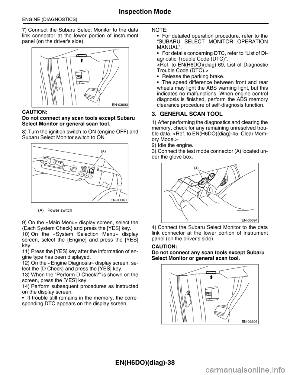
7) Connect the Subaru Select Monitor to the data
link connector at the lower portion of instrument
panel (on the driver's side).
CAUTION:
Do not connect any scan tools except Subaru
Select Monitor or general scan tool.
8) Turn the ignition switch to ON (engine OFF) and
Subaru Select Monitor switch to ON.
9) On the «Main Menu» display screen, select the
{Each System Check} and press the [YES] key.
10) On the «System Selection Menu» display
screen, select the {Engine} and press the [YES]
key.
11) Press the [YES] key after the information of en-
gine type has been displayed.
12) On the «Engine Diagnosis» display screen, se-
lect the {D Check} and press the [YES] key.
13) When the “Perform D Check?” is shown on the
screen, press the [YES] key.
14) Perform subsequent procedures as instructed
on the display screen.
•If trouble still remains in the memory, the corre-
sponding DTC appears on the display screen.
NOTE:
•For detailed operation procedure, refer to the
“SUBARU SELECT MONITOR OPERATION
MANUAL”.
•For details concerning DTC, refer to “List of Di-
agnostic Trouble Code (DTC)”.
•Release the parking brake.
•The speed difference between front and rear
wheels may light the ABS warning light, but this
indicates no malfunctions. When engine control
diagnosis is finished, perform the ABS memory
clearance procedure of self-diagnosis function.
3. GENERAL SCAN TOOL
1) After performing the diagnostics and clearing the
memory, check for any remaining unresolved trou-
ble data.
2) Idle the engine.
3) Connect the test mode connector (A) located un-
der the glove box.
4) Connect the Subaru Select Monitor to the data
link connector at the lower portion of instrument
panel (on the driver’s side).
CAUTION:
Do not connect any scan tools except Subaru
Select Monitor or general scan tool.
(A) Power switch
EN-03693
(A)
EN-00040
EN-03694
(4)
EN-03693
Page 1200 of 2453
EN(H6DO)(diag)-39
Inspection Mode
ENGINE (DIAGNOSTICS)
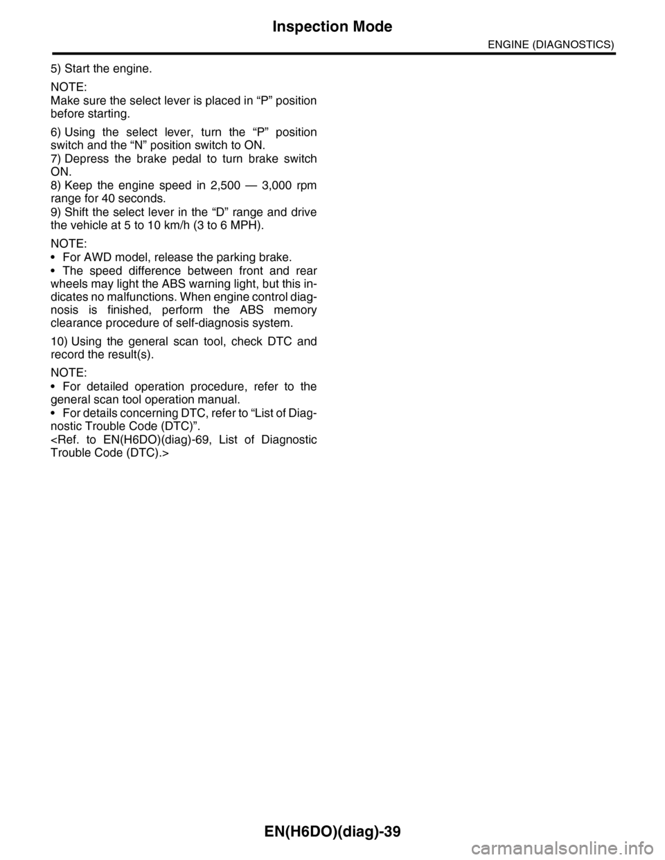
5) Start the engine.
NOTE:
Make sure the select lever is placed in “P” position
before starting.
6) Using the select lever, turn the “P” position
switch and the “N” position switch to ON.
7) Depress the brake pedal to turn brake switch
ON.
8) Keep the engine speed in 2,500 — 3,000 rpm
range for 40 seconds.
9) Shift the select lever in the “D” range and drive
the vehicle at 5 to 10 km/h (3 to 6 MPH).
NOTE:
•For AWD model, release the parking brake.
•The speed difference between front and rear
wheels may light the ABS warning light, but this in-
dicates no malfunctions. When engine control diag-
nosis is finished, perform the ABS memory
clearance procedure of self-diagnosis system.
10) Using the general scan tool, check DTC and
record the result(s).
NOTE:
•For detailed operation procedure, refer to the
general scan tool operation manual.
•For details concerning DTC, refer to “List of Diag-
nostic Trouble Code (DTC)”.
Page 1210 of 2453
EN(H6DO)(diag)-49
Malfunction Indicator Light
ENGINE (DIAGNOSTICS)
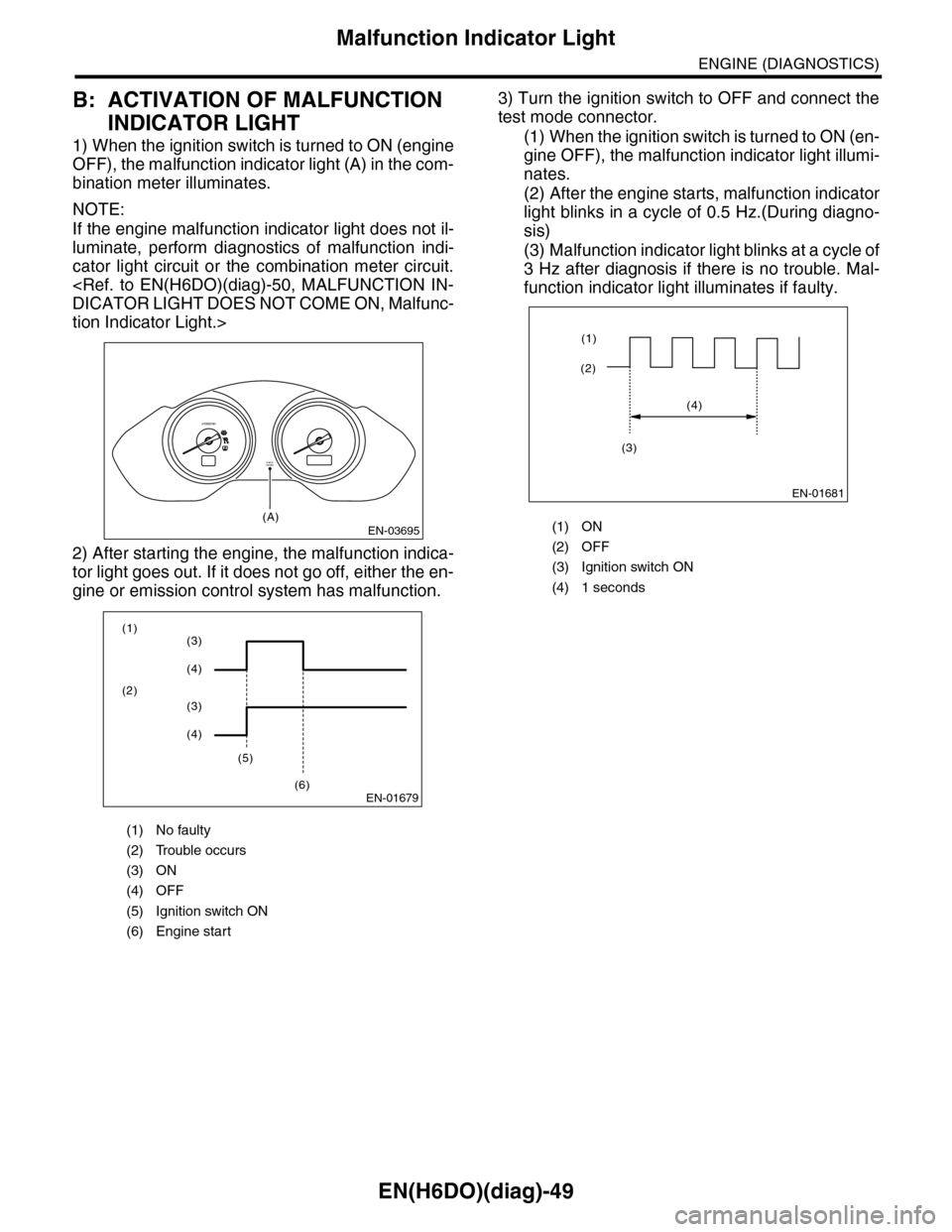
B: ACTIVATION OF MALFUNCTION
INDICATOR LIGHT
1) When the ignition switch is turned to ON (engine
OFF), the malfunction indicator light (A) in the com-
bination meter illuminates.
NOTE:
If the engine malfunction indicator light does not il-
luminate, perform diagnostics of malfunction indi-
cator light circuit or the combination meter circuit.
tion Indicator Light.>
2) After starting the engine, the malfunction indica-
tor light goes out. If it does not go off, either the en-
gine or emission control system has malfunction.
3) Turn the ignition switch to OFF and connect the
test mode connector.
(1) When the ignition switch is turned to ON (en-
gine OFF), the malfunction indicator light illumi-
nates.
(2) After the engine starts, malfunction indicator
light blinks in a cycle of 0.5 Hz.(During diagno-
sis)
(3) Malfunction indicator light blinks at a cycle of
3 Hz after diagnosis if there is no trouble. Mal-
function indicator light illuminates if faulty.
(1) No faulty
(2) Trouble occurs
(3) ON
(4) OFF
(5) Ignition switch ON
(6) Engine start
EN-03695
CHECKENGINE
(A)
x1000/min
EN-01679
(1)
(2)
(5)
(6)
(3)
(4)
(3)
(4)
(1) ON
(2) OFF
(3) Ignition switch ON
(4) 1 seconds
EN-01681
(2)
(1)
(4)
(3)
Page 1211 of 2453
EN(H6DO)(diag)-50
Malfunction Indicator Light
ENGINE (DIAGNOSTICS)
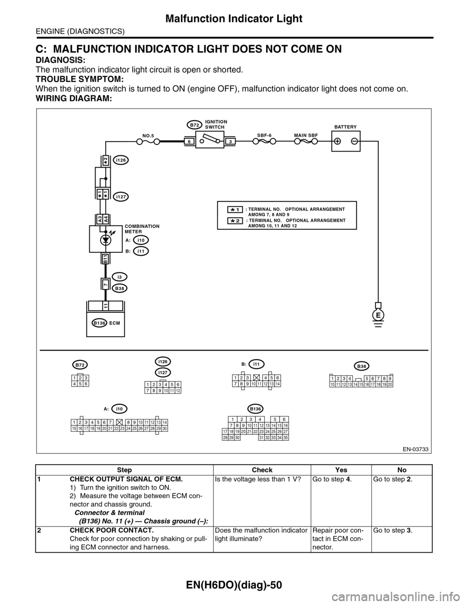
C: MALFUNCTION INDICATOR LIGHT DOES NOT COME ON
DIAGNOSIS:
The malfunction indicator light circuit is open or shorted.
TROUBLE SYMPTOM:
When the ignition switch is turned to ON (engine OFF), malfunction indicator light does not come on.
WIRING DIAGRAM:
EN-03733
3
B72
i3
B38
B136
SBF-66
11
A4
7
MAIN SBFNO.5
B11
E
A3
B72
134562
B38
1234 5678910 11 12 13 14 15 16 17 18 19 20
ECM
COMBINATIONMETER
IGNITIONSWITCHBATTERY
i126
i1271*1*
2*
i10A:
i11B:
i127
i126
123456789101112
1234567891011121314
i11B:
123456789101112131415161718192021222324252627282930
i10A:
2* : TERMINAL NO. OPTIONAL ARRANGEMENT AMONG 10, 11 AND 12
1* : TERMINAL NO. OPTIONAL ARRANGEMENT AMONG 7, 8 AND 9
B136
16101112131415252430
9871718192028212223293231
123456
2726333435
Step Check Yes No
1CHECK OUTPUT SIGNAL OF ECM.
1) Turn the ignition switch to ON.
2) Measure the voltage between ECM con-
nector and chassis ground.
Connector & terminal
(B136) No. 11 (+) — Chassis ground (–):
Is the voltage less than 1 V? Go to step 4.Go to step 2.
2CHECK POOR CONTACT.
Check for poor connection by shaking or pull-
ing ECM connector and harness.
Does the malfunction indicator
light illuminate?
Repair poor con-
tact in ECM con-
nector.
Go to step 3.