2009 SUBARU TRIBECA Starter
[x] Cancel search: StarterPage 418 of 2453

IM (diag)-2
Basic Diagnostic Procedure
IMMOBILIZER (DIAGNOSTICS)
1. Basic Diagnostic Procedure
A: PROCEDURE
Step Check Yes No
1CHECK SECURITY INDICATOR LIGHT.
1) Turn the ignition switch to “OFF” or “ACC”.
2) Wait for 60 seconds or more.
Does the security indicator
light blink?
Go to step 2.Check the secu-
rity indicator light
circuit.
SECURITY INDI-
CATOR LIGHT
CIRCUIT,
INSPECTION,
Diagnostics Chart
for Secur ity Indica-
tor Light.>
2CHECK KEY SWITCH.
Remove the key from ignition switch.
Does the security indicator
light blink within 1 second after
removing the key?
Go to step 3.Check the key
switch circuit.
SWITCH CIR-
CUIT, INSPEC-
TION, Diagnostics
Chart for Security
Indicator Light.>
3CHECK SECURITY INDICATOR LIGHT.
Tu r n t h e i g n i t i o n s w i t c h t o O N .
Does the security indicator
light go off?
Go to step 5.Go to step 4.
4CHECK ENGINE START.
Tu r n t h e i g n i t i o n s w i t c h t o S TA R T.
Does the starter operate? Check the LAN
communication cir-
cuit.
Diagnostic Proce-
dure.>
Check the DTC
display (body inte-
grated unit). Go to
step 7.
5CHECK ENGINE START.
Tu r n t h e i g n i t i o n s w i t c h t o S TA R T.
Does the starter operate? Go to step 6.Check the LAN
communication cir-
cuit.
Diagnostic Proce-
dure.>
6CHECK ENGINE START.
Tu r n t h e i g n i t i o n s w i t c h t o S TA R T.
Does the engine start? Immobilizer sys-
tem is OK.
Check the DTC
display (ECM). Go
to step 7.
7CHECK ANY OTHER DTC ON DISPLAY.
1) Turn the ignition switch to OFF.
2) Connect the Subaru Select Monitor to data
link connector.
3) Turn the ignition switch and Subaru Select
Monitor switch to ON.
4) Read DTC on display.
Is the DTC displayed on
screen?
Go to step 8.Repair the related
parts.
8PERFORM THE DIAGNOSIS.
1) Inspect using the “Diagnostic Procedure
with Diagnostic Trouble Code (DTC).”
nostic Trouble Code (DTC).>
2) Repair the trouble cause.
3) Perform the clear memory mode.
4) Read DTC again.
Is the DTC displayed on
screen?
Inspect using the
“Diagnostic Proce-
dure with Diagnos-
tic Trouble Code
(DTC).”
nostic Procedure
with Diagnostic
Tr o u b l e C o d e
(DTC).>
Finish the diagno-
sis.
Page 431 of 2453

IM (diag)-15
List of Diagnostic Trouble Code (DTC)
IMMOBILIZER (DIAGNOSTICS)
2. BODY INTEGRATED UNIT
NOTE:
In immobilizer system, performing the starter relay control. When the body integrated unit detect the incon-
formity of reference code, immediately out put the starter relay cut signal to ECM, and then ECM stop the
starter relay operation. In this case, engine does not start, and DTC is not recorded in ECM. Check that the
engine does not start on the DTC of body integrated unit.
DTC Item Contents of diagnosis Index No.Relation between
ECM and DTC
B0401 M collation
NG
Reference code incompati-
bility between body inte-
grated unit and combination
meter
Code (DTC).>
P1578
B0402 Immobilizer
Key collation
NG
•Incorrect immobilizer key
(Use of unregistered key in
body integrated unit)
•Faulty antenna
Diagnostic Trouble Code (DTC).>
with Diagnostic Trouble Code (DTC).>or
FA I L U R E , D i a g n o s t i c P r o c e d u r e w i t h D i a g n o s t i c
Tr o u b l e C o d e ( D T C ) . >
•P0513
•P1570
•P1574
B0403 E/G request
NG
Communication failure
between body integrated
unit and ECM
tic Procedure with Diagnostic Trouble Code (DTC).>
P1572
Page 471 of 2453

LAN(diag)-15
Subaru Select Monitor
LAN SYSTEM (DIAGNOSTICS)
P seatbelt SW input ON/OFFBody integrated unit input
valuePa s se ng e r ’s se at bu ckl e sw it c h ON
Fr wi pe r in p ut O N/O FFBody integrated unit input
valueOn when front wiper is operating
Registration SW input ON/OFFBody integrated unit input
value
Not supported by North American specifica-
tions
Identification SW input ON/OFFBody integrated unit input
value
Not supported by North American specifica-
tions
R defogger output ON/OFFBody integrated unit output
valueOn when rear defogger relay is operating
Door lock actuator LOCK
outputON/OFFBody integrated unit output
valueOn when lock signal is output
All seat UNLOCK output ON/OFFBody integrated unit output
valueOn when unlock signal is output
D-seat UNLOCK output ON/OFFBody integrated unit output
valueOn when unlock signal is output
R gate/trunk UNLK output ON/OFFBody integrated unit output
value
On when rear gate/trunk unlock signal is
output
Double lock output ON/OFFBody integrated unit output
value
Not supported by North American specifica-
tions
R wiper output ON/OFFBody integrated unit output
valueOn when rear wiper is operating
Shift Lock Solenoid ON/OFFBody integrated unit output
valueOn when shift lock solenoid is operating
Key locking output ON/OFFBody integrated unit output
valueOn when key lock solenoid is operating
wiper deicer SW input ON/OFFBody integrated unit output
valueOn when wiper deicer is operating
Starter cutting output ON/OFFBody integrated unit output
value
Not supported by North American specifica-
tions
Hazard Output ON/OFFBody integrated unit output
value
On when keyless lock/unlock signal is
received (when keyless switch connector is
removed)
Keyless Buzzer Output ON/OFFBody integrated unit output
value
On when keyless lock/unlock signal is
received (when keyless switch connector is
removed)
Horn Output ON/OFFBody integrated unit output
valueOn when security warning is operating
Siren Output ON/OFFBody integrated unit output
value
On when siren is installed, customize set-
tings are enabled, and security warning is
operating
D-belt warning light O/P ON/OFFBody integrated unit output
value
On when Ignition switch is turned to ON,
and buckle switch is turned off
P-belt warning light O/P ON/OFFBody integrated unit output
value
On when Ignition switch is turned to ON,
occupant is seated, and buckle switch is
turned off
Illumination lamp O/P ON/OFFBody integrated unit output
valueOn when illumination is illuminated
Room lamp output ON/OFFBody integrated unit output
value
On when keyless lock/unlock signal is
received (when keyless switch connector is
removed)
key illumi. lamp o/p ON/OFFBody integrated unit output
valueOn when key illumination light is illuminated
R fog light output ON/OFFBody integrated unit output
value
Not supported by North American specifica-
tions
R fog lamp monitor ON/OFFBody integrated unit output
value
Not supported by North American specifica-
tions
Items to be displayed Unit of measure Description Note
Page 1176 of 2453

EN(H6DO)(diag)-15
Electrical Component Location
ENGINE (DIAGNOSTICS)
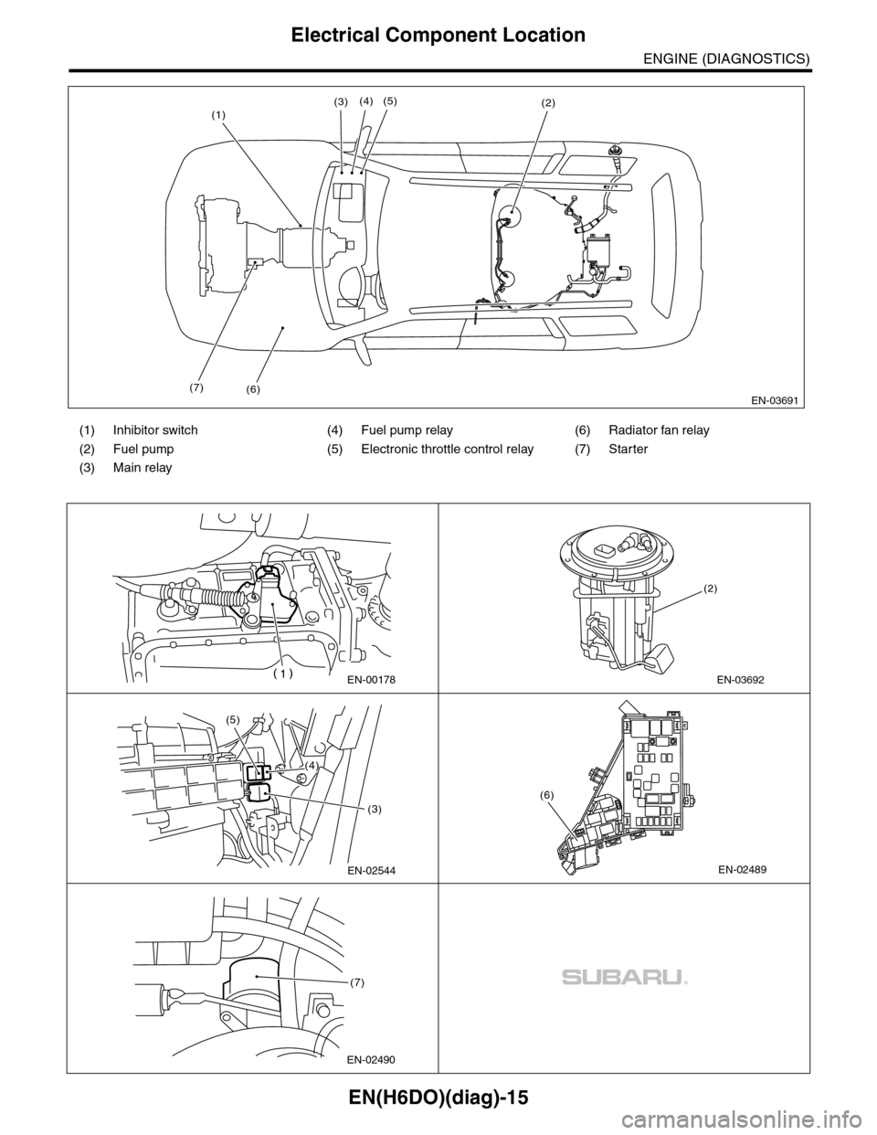
(1) Inhibitor switch (4) Fuel pump relay (6) Radiator fan relay
(2) Fuel pump (5) Electronic throttle control relay (7) Starter
(3) Main relay
EN-03691(6)
(3)(2)
(7)
(1)(4) (5)
EN-00178EN-03692
(2)
EN-02544
(3)
(4)
(5)
EN-02489
(6)
EN-02490
(7)
Page 1178 of 2453

EN(H6DO)(diag)-17
Engine Control Module (ECM) I/O Signal
ENGINE (DIAGNOSTICS)
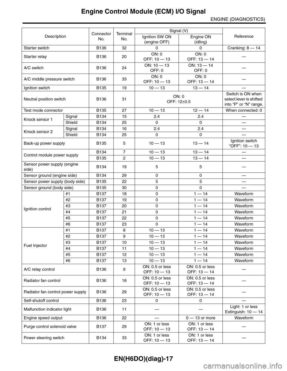
Starter switch B136 32 0 0 Cranking: 8 — 14
Starter relay B136 20ON: 0
OFF: 10 — 13
ON: 0
OFF: 13 — 14—
A/C switch B136 24ON: 10 — 13
OFF: 0
ON: 13 — 14
OFF: 0—
A/C middle pressure switch B136 33ON: 0
OFF: 10 — 13
ON: 0
OFF: 13 — 14—
Ignition switch B135 19 10 — 13 13 — 14 —
Neutral position switch B136 31ON: 0
OFF: 12±0.5
Switch is ON when
select lever is shifted
into “P” or “N” range.
Te s t m o d e c o n n e c t o r B 1 3 5 2 7 1 0 — 1 3 1 2 — 1 4 W h e n c o n n e c t e d : 0
Knock sensor 1Signal B134 15 2.4 2.4 —
Shield B134 25 0 0 —
Knock sensor 2Signal B134 16 2.4 2.4 —
Shield B134 25 0 0 —
Back-up power supply B135 5 10 — 13 13 — 14Ignition switch
“OFF”: 10 — 13
Control module power supplyB134 7 10 — 13 13 — 14 —
B135 2 10 — 13 13 — 14 —
Sensor power supply (engine
side)B134 19 5 5 —
Sensor ground (engine side) B134 29 0 0 —
Sensor power supply (body side) B135 22 5 5 —
Sensor ground (body side) B135 30 0 0 —
Ignition control
#1 B137 18 0 1 — 14 Waveform
#2 B137 19 0 1 — 14 Waveform
#3 B137 20 0 1 — 14 Waveform
#4 B137 21 0 1 — 14 Waveform
#5 B137 22 0 1 — 14 Waveform
#6 B137 23 0 1 — 14 Waveform
Fuel Injector
#1 B137 8 10 — 13 1 — 14 Waveform
#2 B137 9 10 — 13 1 — 14 Waveform
#3 B137 10 10 — 13 1 — 14 Waveform
#4 B137 11 10 — 13 1 — 14 Waveform
#5 B137 12 10 — 13 1 — 14 Waveform
#6 B137 13 10 — 13 1 — 14 Waveform
A/C relay control B136 9ON: 0.5 or less
OFF: 10 — 13
ON: 0.5 or less
OFF: 13 — 14—
Radiator fan control B136 18ON: 0.5 or less
OFF: 10 — 13
ON: 0.5 or less
OFF: 13 — 14—
Radiator fan control power supply B136 29ON: 0.5 or less
OFF: 10 — 13
ON: 0.5 or less
OFF: 13 — 14—
Self-shutoff control B136 23 0 0 —
Malfunction indicator light B136 11 — —Light: 1 or less
Extinguish: 10 — 14
Engine speed output B136 22 — 0 — 13 or more Waveform
Purge control solenoid valve B137 29ON: 1 or less
OFF: 10 — 13
ON: 1 or less
OFF: 13 — 14—
Pow er s te e r in g sw it c h B 1 3 4 33ON: 1 or less
OFF: 10 — 13
ON: 1 or less
OFF: 13 — 14—
DescriptionConnector
No.
Te r m i n a l
No.
Signal (V)
ReferenceIgnition SW ON
(engine OFF)
Engine ON
(idling)
Page 1189 of 2453

EN(H6DO)(diag)-28
Subaru Select Monitor
ENGINE (DIAGNOSTICS)
Fr o nt ox yg e n ( A / F) s en so r r es is t an ce val ue 2 A / F s en s or r e si st a nc e val u e 2Ω31 Ω
Fr o nt ox yg e n ( A / F) s en so r ou t p ut la m bd a 1 A / F s en s or o ut p ut l am bd a 1 — 1 . 00
Fr o nt ox yg e n ( A / F) s en so r ou t p ut la m bd a 2 A / F s en s or o ut p ut l am bd a 2 — 1 . 00
Fuel tank pressure signal Fuel Tank PressuremmHg, kPa,
inHg or psig
+8.8 mmHg, +1.2 kPa,
+0.4 inHg or +0.17 psig
Fuel temperature signal Fuel Temp. °C or °F +28°C or +82°F
A/F compensation 3 A/F Compensation 3 % –0.16%
A/F learning 3 A/F learning 3 % 0.0%
Throttle motor duty Throttle motor duty % –27%
Throttle power supply voltage Throttle power supply voltage V (Battery voltage)
Sub throttle sensor voltage Sub throttle sensor voltage V 1.50 V
Main throttle sensor voltage Main throttle sensor voltage V 0.64 V
Sub acceleration sensor voltage Sub acceleration sensor voltage V 0.7 V
Main acceleration sensor voltage Main acceleration sensor voltage V 0.7 V
Memory vehicle speed Memory vehicle speed km/h or MPH 0 km/h or 0 MPH
A/F compensation 4 A/F Compensation 4 % 0.31%
A/F learning 4 A/F learning 4 % 0.0%
Fuel level sensor resistance Fuel level resistanceΩ4 — 96 Ω
Oil temperature Oil Temperature °C≥ 85°C (After engine is
warmed-up.)
Oil switching solenoid valve duty R OSV duty R % 17.3%
Oil switching solenoid valve duty L OSV duty L % 17.3%
Oil switching solenoid valve current R OSV current R mA 192 mA
Oil switching solenoid valve current L OSV current L mA 192 mA
Va r i a b l e va l v e l i f t m o d e V V L L i f t M o d e — 1
#1 cylinder roughness monitor #1 cylinder roughness monitor — 0
#2 cylinder roughness monitor #2 cylinder roughness monitor — 0
#3 cylinder roughness monitor #3 cylinder roughness monitor — 0
#4 cylinder roughness monitor #4 cylinder roughness monitor — 0
#5 cylinder roughness monitor #5 cylinder roughness monitor — 0
#6 cylinder roughness monitor #6 cylinder roughness monitor — 0
Te s t m o d e t e r m i n a l Te s t m o d e t e r m i n a l — U c h e c k
Neutral position switch signal Neutral SW — Neutral
Idle switch signal Soft idle SW — In idle
Ignition switch signal Ignition SW — ON input
Pow er s te e r in g sw it c h s ig n al Powe r st ee r i ng S W i n pu t si gn a l — O FF i np u t ( w h e n OF F )
Air conditioning switch signal A/C SW — OFF input (when OFF)
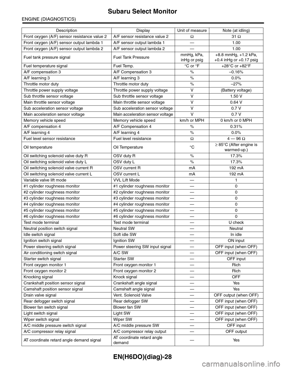
Starter switch signal Starter SW — OFF input
Fr o nt ox yg e n mo n it o r 1 Fr o n t oxy ge n m on i to r 1 — Ri ch
Fr o nt ox yg e n mo n it o r 2 Fr o n t oxy ge n m on i to r 2 — Ri ch
Knocking signal Knock signal — OFF
Crankshaft position sensor signal Crankshaft angle signal — Yes
Camshaft position sensor signal Camshaft angle signal — Yes
Drain valve signal Vent. Solenoid Valve — OFF output (when OFF)
Rear defogger switch signal Rear defogger SW — OFF input (when OFF)
Blower fan switch signal Blower fan SW — OFF input (when OFF)
Light switch signal Light SW — OFF input (when OFF)
Wiper switch signal Wiper SW — OFF input (when OFF)
A/C middle pressure switch signal A/C middle pressure SW — OFF input
A/C compressor relay signal A/C compressor relay output — OFF output
AT c o o r d i n a t e r e t a r d a n g l e d e m a n d s i g n a lAT c o o r d i n a t e r e t a r d a n g l e
demand—Yes
Description Display Unit of measure Note (at idling)
Page 1193 of 2453
![SUBARU TRIBECA 2009 1.G Service Workshop Manual EN(H6DO)(diag)-32
Subaru Select Monitor
ENGINE (DIAGNOSTICS)
7. LED OPERATION MODE FOR ENGINE
1) On the «Main Menu» display screen, select the {Each System Check} and press the [YES] key.
2) On the SUBARU TRIBECA 2009 1.G Service Workshop Manual EN(H6DO)(diag)-32
Subaru Select Monitor
ENGINE (DIAGNOSTICS)
7. LED OPERATION MODE FOR ENGINE
1) On the «Main Menu» display screen, select the {Each System Check} and press the [YES] key.
2) On the](/manual-img/17/7322/w960_7322-1192.png)
EN(H6DO)(diag)-32
Subaru Select Monitor
ENGINE (DIAGNOSTICS)
7. LED OPERATION MODE FOR ENGINE
1) On the «Main Menu» display screen, select the {Each System Check} and press the [YES] key.
2) On the «System Selection Menu» display screen, select the {Engine} and press the [YES] key.
3) Press the [YES] key after the information of engine type has been displayed.
4) On the «Engine Diagnosis» display screen, select the {Current Data Display/Save}, and then press the
[YES] key.
5) On the «Data Display» screen, select the {Data LED Display} and press the [YES] key.
6) Using the scroll key, scroll the display screen up or down until the desired data is shown.
•A list of the support data is shown in the following table.
NOTE:
For detailed operation procedure, refer to the “SUBARU SELECT MONITOR OPERATION MANUAL”.
Description Display Message When LED “ON” required
Te s t m o d e s i g n a l Te s t m o d e t e r m i n a l D c h e c k / U c h e c k D c h e c k
Neutral position switch signal Neutral SW Neutral/Other than neutral Neutral
Idle switch signal Soft idle SW Idle/Other than idle In idle
Ignition switch signal Ignition SW ON Input/OFF Input ON input
Pow er s te e r in g sw it c h s ig n al Pow er s te e r in g S W ON I np u t/ O FF I np u t ON i np ut
Air conditioning switch signal A/C SW ON Input/OFF Input ON input
Starter switch signal Starter SW ON Input/OFF Input ON input
Fr o nt ox yg e n mo n it o r 1 Ft O 2 mo n it o r 1 Le a n/ Ri ch Ric h
Fr o nt ox yg e n mo n it o r 2 Ft O 2 mo n it o r 2 Le a n/ Ri ch Ric h
Knocking signal Knock signal Yes/No Yes
Crankshaft position sensor signal Crankshaft angle signal Yes/No Yes
Camshaft position sensor signal Camshaft angle signal Yes/No Yes
Rear defogger switch signal Rear defogger SW ON Input/OFF Input ON input
Blower fan switch signal Blower fan SW ON Input/OFF Input ON input
Light switch signal Light SW ON Input/OFF Input ON input
Wiper switch signal Wiper SW ON Input/OFF Input ON input
A/C middle pressure switch signal A/C middle pressure SW ON Input/OFF Input ON input
Air conditioner compressor relay sig-
nalCompressor relay ON output/OFF output ON output
Drain valve signal Vent. Solenoid Valve ON or OFF When drain valve is ON.
AT r e t a r d a n g l e d e m a n d s i g n a l AT r e t a r d a n g l e d e m a n d Ye s / N o Ye s
AT f u e l c u t s i g n a l AT f u e l c u t Ye s / N o Ye s
VDC torque down prohibition output Torque down output ON/OFF Prohibition
VDC torque down demand Torque down demand Yes/No Yes
AT c o o r d i n a t e p e r m i s s i o n s i g n a lAT c o o r d i n a t e p e r m i s s i o n
signalON/OFF Permission
Electronic throttle control motor relay
signalETC motor relay ON/OFF ON
Stop light switch signal Stop SW ON Input/OFF Input ON input
SET/COAST switch signal SET/CST SW ON Input/OFF Input ON input
RESUME/ACCEL switch signal RES/ACC SW ON Input/OFF Input ON input
Brake switch signal Brake SW ON Input/OFF Input ON input
Main switch signal Main SW ON Input/OFF Input ON input
Body integrated unit data reception Body Int. Unit Data Yes/No Yes
Body integrated unit counter update Body Int. Unit Count Yes/No Yes
Cruise control cancel switch signal CC Cancel SW ON Input/OFF Input ON input
Va r i a b l e va l v e l i f t d i a g n o s i s o i l p r e s -
sure switch signal 1Oil Temperature SW1 ON/OFF ON
Va r i a b l e va l v e l i f t d i a g n o s i s o i l p r e s -
sure switch signal 2Oil Temperature SW2 ON/OFF ON
Page 1197 of 2453

EN(H6DO)(diag)-36
Inspection Mode
ENGINE (DIAGNOSTICS)
P0340 Camshaft Position Sensor “A” Circuit (Bank 1 or Single Sensor) —
P0345 Camshaft Position Sensor “A” Circuit (Bank 2) —
P0447 Evaporative Emission Control System Vent Control Circuit Open —
P0448 Evaporative Emission Control System Vent Control Circuit Shorted —
P0452 Evaporative Emission Control System Pressure Sensor Low Input —
P0453 Evaporative Emission Control System Pressure Sensor High Input —
P0458 Evaporative Emission Control System Purge Control Valve Circuit Low —
P0462 Fuel Level Sensor Circuit Low Input —
P0463 Fuel Level Sensor Circuit High Input —
P0500 Vehicle Speed Sensor—
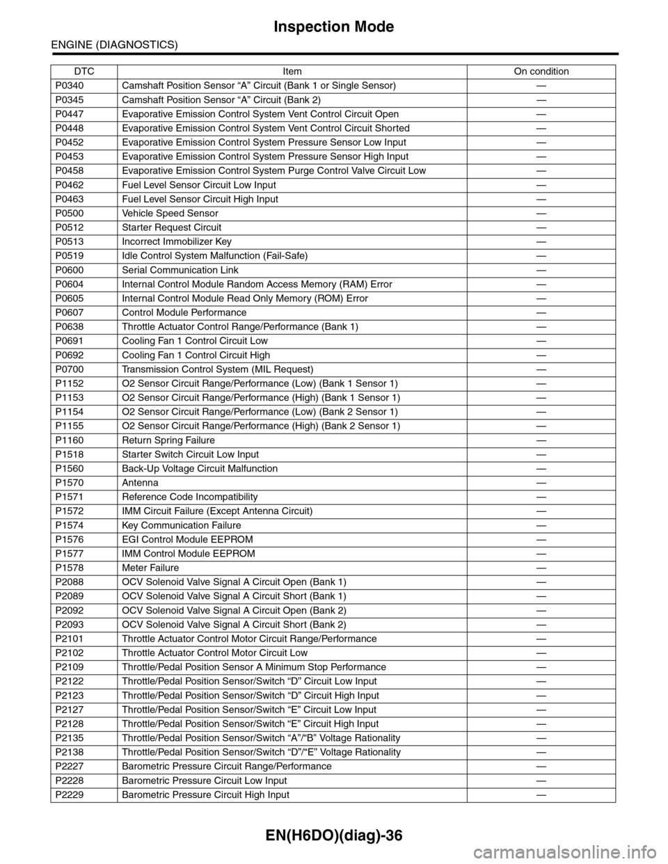
P0512 Starter Request Circuit—
P0513 Incorrect Immobilizer Key —
P0519 Idle Control System Malfunction (Fail-Safe) —
P0600 Serial Communication Link —
P0604 Internal Control Module Random Access Memory (RAM) Error —
P0605 Internal Control Module Read Only Memory (ROM) Error —
P0607 Control Module Performance —
P0638 Throttle Actuator Control Range/Performance (Bank 1) —
P0691 Cooling Fan 1 Control Circuit Low —
P0692 Cooling Fan 1 Control Circuit High —
P0700 Transmission Control System (MIL Request) —
P1152 O2 Sensor Circuit Range/Performance (Low) (Bank 1 Sensor 1) —
P1153 O2 Sensor Circuit Range/Performance (High) (Bank 1 Sensor 1) —
P1154 O2 Sensor Circuit Range/Performance (Low) (Bank 2 Sensor 1) —
P1155 O2 Sensor Circuit Range/Performance (High) (Bank 2 Sensor 1) —
P1160 Return Spring Failure—
P1518 Starter Switch Circuit Low Input —
P1560 Back-Up Voltage Circuit Malfunction —
P1570 Antenna—
P1571 Reference Code Incompatibility —
P1572 IMM Circuit Failure (Except Antenna Circuit) —
P1574 Key Communication Failure —
P1576 EGI Control Module EEPROM —
P1577 IMM Control Module EEPROM —
P1578 Meter Failure—
P2088 OCV Solenoid Valve Signal A Circuit Open (Bank 1) —
P2089 OCV Solenoid Valve Signal A Circuit Short (Bank 1) —
P2092 OCV Solenoid Valve Signal A Circuit Open (Bank 2) —
P2093 OCV Solenoid Valve Signal A Circuit Short (Bank 2) —
P2101 Throttle Actuator Control Motor Circuit Range/Performance —
P2102 Throttle Actuator Control Motor Circuit Low —
P2109 Throttle/Pedal Position Sensor A Minimum Stop Performance —
P2122 Throttle/Pedal Position Sensor/Switch “D” Circuit Low Input —
P2123 Throttle/Pedal Position Sensor/Switch “D” Circuit High Input —
P2127 Throttle/Pedal Position Sensor/Switch “E” Circuit Low Input —
P2128 Throttle/Pedal Position Sensor/Switch “E” Circuit High Input —
P2135 Throttle/Pedal Position Sensor/Switch “A”/“B” Voltage Rationality —
P2138 Throttle/Pedal Position Sensor/Switch “D”/“E” Voltage Rationality —
P2227 Barometric Pressure Circuit Range/Performance —
P2228 Barometric Pressure Circuit Low Input —
P2229 Barometric Pressure Circuit High Input —
DTC Item On condition