2009 SUBARU TRIBECA Starter
[x] Cancel search: StarterPage 1782 of 2453
GD(H6DO)-170
Diagnostic Trouble Code (DTC) Detecting Criteria
GENERAL DESCRIPTION
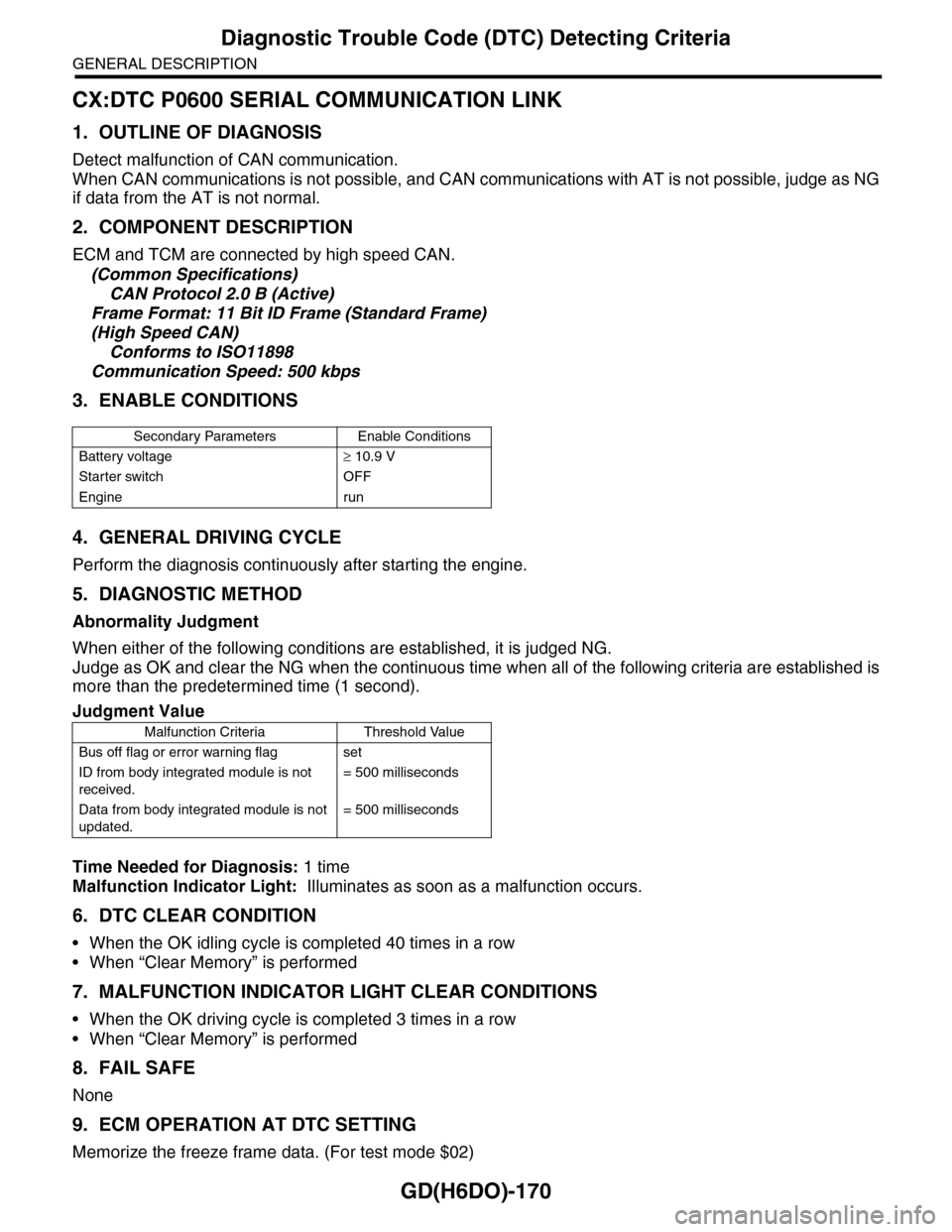
CX:DTC P0600 SERIAL COMMUNICATION LINK
1. OUTLINE OF DIAGNOSIS
Detect malfunction of CAN communication.
When CAN communications is not possible, and CAN communications with AT is not possible, judge as NG
if data from the AT is not normal.
2. COMPONENT DESCRIPTION
ECM and TCM are connected by high speed CAN.
(Common Specifications)
CAN Protocol 2.0 B (Active)
Frame Format: 11 Bit ID Frame (Standard Frame)
(High Speed CAN)
Conforms to ISO11898
Communication Speed: 500 kbps
3. ENABLE CONDITIONS
4. GENERAL DRIVING CYCLE
Perform the diagnosis continuously after starting the engine.
5. DIAGNOSTIC METHOD
Abnormality Judgment
When either of the following conditions are established, it is judged NG.
Judge as OK and clear the NG when the continuous time when all of the following criteria are established is
more than the predetermined time (1 second).
Time Needed for Diagnosis: 1 time
Malfunction Indicator Light: Illuminates as soon as a malfunction occurs.
6. DTC CLEAR CONDITION
•When the OK idling cycle is completed 40 times in a row
•When “Clear Memory” is performed
7. MALFUNCTION INDICATOR LIGHT CLEAR CONDITIONS
•When the OK driving cycle is completed 3 times in a row
•When “Clear Memory” is performed
8. FAIL SAFE
None
9. ECM OPERATION AT DTC SETTING
Memorize the freeze frame data. (For test mode $02)
Secondary Parameters Enable Conditions
Battery voltage≥ 10.9 V
Starter switch OFF
Engine run
Judgment Value
Malfunction Criteria Threshold Value
Bus off flag or error warning flag set
ID from body integrated module is not
received.
= 500 milliseconds
Data from body integrated module is not
updated.
= 500 milliseconds
Page 1803 of 2453
GD(H6DO)-191
Diagnostic Trouble Code (DTC) Detecting Criteria
GENERAL DESCRIPTION
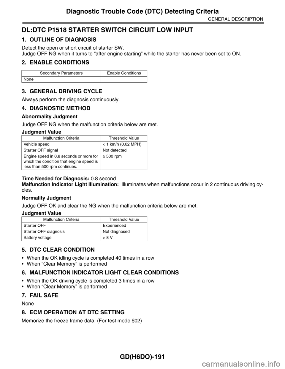
DL:DTC P1518 STARTER SWITCH CIRCUIT LOW INPUT
1. OUTLINE OF DIAGNOSIS
Detect the open or short circuit of starter SW.
Judge OFF NG when it turns to “after engine starting” while the starter has never been set to ON.
2. ENABLE CONDITIONS
3. GENERAL DRIVING CYCLE
Always perform the diagnosis continuously.
4. DIAGNOSTIC METHOD
Abnormality Judgment
Judge OFF NG when the malfunction criteria below are met.
Time Needed for Diagnosis: 0.8 second
Malfunction Indicator Light Illumination: Illuminates when malfunctions occur in 2 continuous driving cy-
cles.
Normality Judgment
Judge OFF OK and clear the NG when the malfunction criteria below are met.
5. DTC CLEAR CONDITION
•When the OK idling cycle is completed 40 times in a row
•When “Clear Memory” is performed
6. MALFUNCTION INDICATOR LIGHT CLEAR CONDITIONS
•When the OK driving cycle is completed 3 times in a row
•When “Clear Memory” is performed
7. FAIL SAFE
None
8. ECM OPERATION AT DTC SETTING
Memorize the freeze frame data. (For test mode $02)
Secondary Parameters Enable Conditions
None
Judgment Value
Malfunction Criteria Threshold Value
Ve h i c l e s p e e d < 1 k m / h ( 0 . 6 2 M P H )
Starter OFF signal Not detected
Engine speed in 0.8 seconds or more for
which the condition that engine speed is
less than 500 rpm continues.
≥ 500 rpm
Judgment Value
Malfunction Criteria Threshold Value
Starter OFF Experienced
Starter OFF diagnosis Not diagnosed
Battery voltage > 8 V
Page 1887 of 2453
ME(H6DO)-21
Compression
MECHANICAL
2. Compression
A: INSPECTION
CAUTION:
After warming-up, engine becomes very hot. Be
careful not to burn yourself during measure-
ment.
1) After warming-up the engine, turn the ignition
switch to OFF.
2) Make sure that the battery is fully charged.
3) Release the fuel pressure.
4) Remove all the spark plugs.
5) Check the starter motor for satisfactory perfor-
mance and operation.
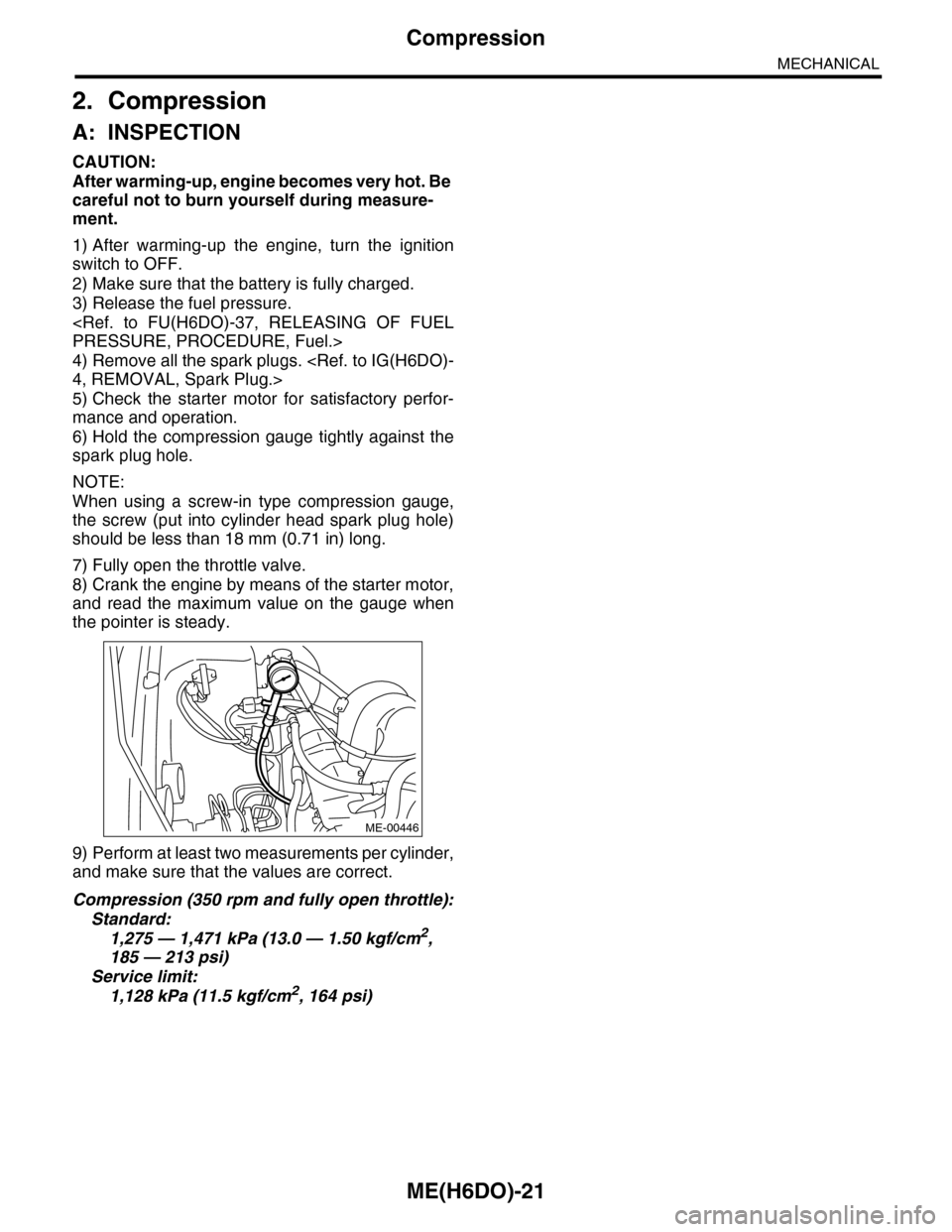
6) Hold the compression gauge tightly against the
spark plug hole.
NOTE:
When using a screw-in type compression gauge,
the screw (put into cylinder head spark plug hole)
should be less than 18 mm (0.71 in) long.
7) Fully open the throttle valve.
8) Crank the engine by means of the starter motor,
and read the maximum value on the gauge when
the pointer is steady.
9) Perform at least two measurements per cylinder,
and make sure that the values are correct.
Compression (350 rpm and fully open throttle):
Standard:
1,275 — 1,471 kPa (13.0 — 1.50 kgf/cm2,
185 — 213 psi)
Service limit:
1,128 kPa (11.5 kgf/cm2, 164 psi)
ME-00446
Page 1901 of 2453
ME(H6DO)-35
Engine Assembly
MECHANICAL
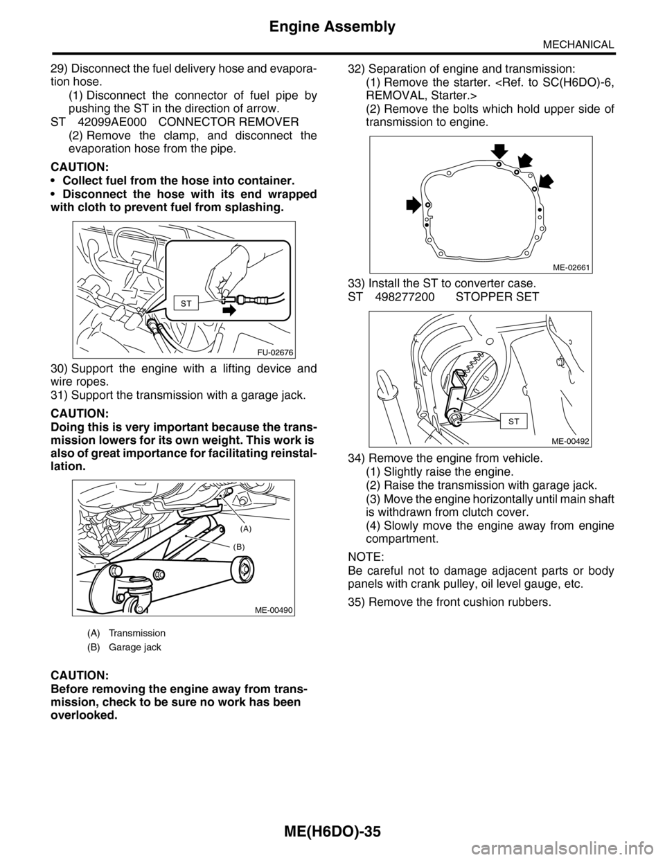
29) Disconnect the fuel delivery hose and evapora-
tion hose.
(1) Disconnect the connector of fuel pipe by
pushing the ST in the direction of arrow.
ST 42099AE000 CONNECTOR REMOVER
(2) Remove the clamp, and disconnect the
evaporation hose from the pipe.
CAUTION:
•Collect fuel from the hose into container.
•Disconnect the hose with its end wrapped
with cloth to prevent fuel from splashing.
30) Support the engine with a lifting device and
wire ropes.
31) Support the transmission with a garage jack.
CAUTION:
Doing this is very important because the trans-
mission lowers for its own weight. This work is
also of great importance for facilitating reinstal-
lation.
CAUTION:
Before removing the engine away from trans-
mission, check to be sure no work has been
overlooked.
32) Separation of engine and transmission:
(1) Remove the starter.
(2) Remove the bolts which hold upper side of
transmission to engine.
33) Install the ST to converter case.
ST 498277200 STOPPER SET
34) Remove the engine from vehicle.
(1) Slightly raise the engine.
(2) Raise the transmission with garage jack.
(3) Move the engine horizontally until main shaft
is withdrawn from clutch cover.
(4) Slowly move the engine away from engine
compartment.
NOTE:
Be careful not to damage adjacent parts or body
panels with crank pulley, oil level gauge, etc.
35) Remove the front cushion rubbers.
(A) Transmission
(B) Garage jack
(A)
(B)
ME-00490
ME-02661
ST
ME-00492
Page 1902 of 2453
ME(H6DO)-36
Engine Assembly
MECHANICAL
B: INSTALLATION
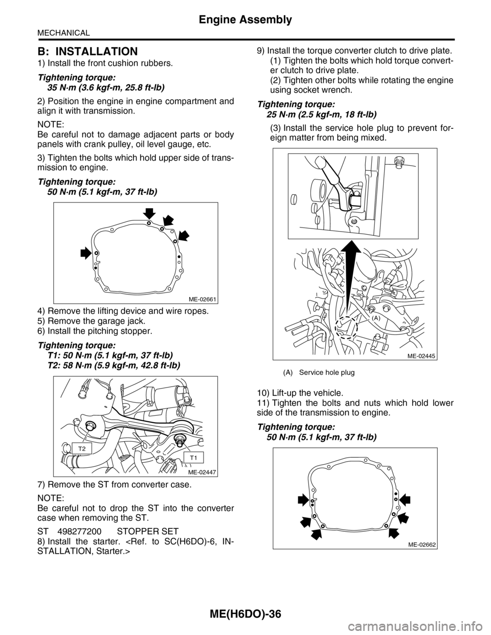
1) Install the front cushion rubbers.
Tightening torque:
35 N·m (3.6 kgf-m, 25.8 ft-lb)
2) Position the engine in engine compartment and
align it with transmission.
NOTE:
Be careful not to damage adjacent parts or body
panels with crank pulley, oil level gauge, etc.
3) Tighten the bolts which hold upper side of trans-
mission to engine.
Tightening torque:
50 N·m (5.1 kgf-m, 37 ft-lb)
4) Remove the lifting device and wire ropes.
5) Remove the garage jack.
6) Install the pitching stopper.
Tightening torque:
T1: 50 N·m (5.1 kgf-m, 37 ft-lb)
T2: 58 N·m (5.9 kgf-m, 42.8 ft-lb)
7) Remove the ST from converter case.
NOTE:
Be careful not to drop the ST into the converter
case when removing the ST.
ST 498277200 STOPPER SET
8) Install the starter.
9) Install the torque converter clutch to drive plate.
(1) Tighten the bolts which hold torque convert-
er clutch to drive plate.
(2) Tighten other bolts while rotating the engine
using socket wrench.
Tightening torque:
25 N·m (2.5 kgf-m, 18 ft-lb)
(3) Install the service hole plug to prevent for-
eign matter from being mixed.
10) Lift-up the vehicle.
11) Tighten the bolts and nuts which hold lower
side of the transmission to engine.
Tightening torque:
50 N·m (5.1 kgf-m, 37 ft-lb)
ME-02661
T2
T1
ME-02447
(A) Service hole plug
(A)
ME-02445
ME-02662
Page 1949 of 2453
ME(H6DO)-83
Engine Trouble in General
MECHANICAL
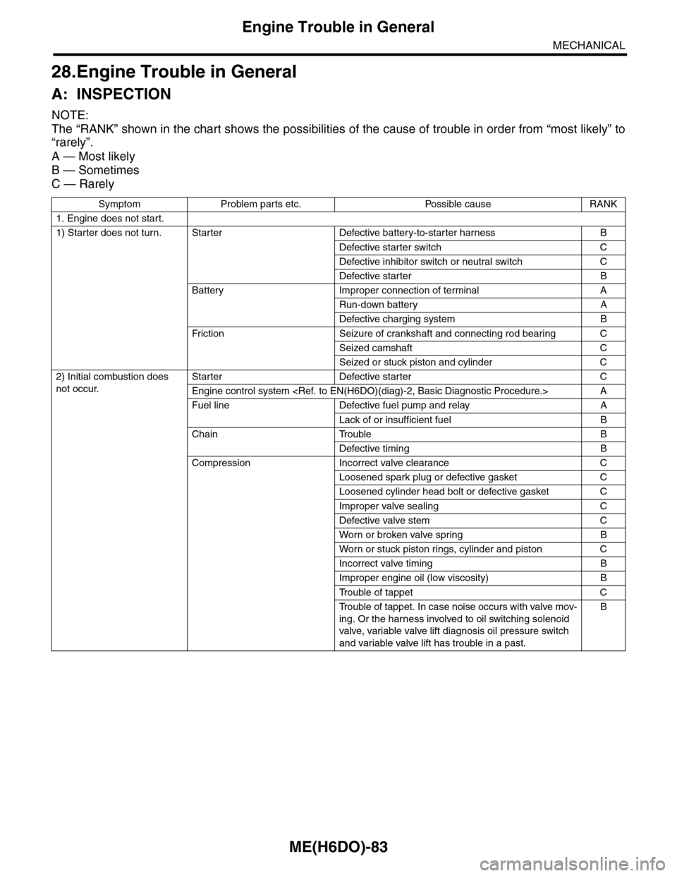
28.Engine Trouble in General
A: INSPECTION
NOTE:
The “RANK” shown in the chart shows the possibilities of the cause of trouble in order from “most likely” to
“rarely”.
A — Most likely
B — Sometimes
C — Rarely
Symptom Problem parts etc. Possible cause RANK
1. Engine does not start.
1) Starter does not turn. Starter Defective battery-to-starter harness B
Defective starter switch C
Defective inhibitor switch or neutral switch C
Defective starter B
Battery Improper connection of terminal A
Run-down battery A
Defective charging system B
Fr iction Seizure of crankshaft and connecting rod bear ing C
Seized camshaft C
Seized or stuck piston and cylinder C
2) Initial combustion does
not occur.
Starter Defective starter C
Engine control system
Fuel line Defective fuel pump and relay A
Lack of or insufficient fuel B
Chain Trouble B
Defective timing B
Compression Incorrect valve clearance C
Loosened spark plug or defective gasket C
Loosened cylinder head bolt or defective gasket C
Improper valve sealing C
Defective valve stem C
Wor n or broken valve spr ing B
Wor n or stuck piston r ings, cylinder and piston C
Incorrect valve timing B
Improper engine oil (low viscosity) B
Tr o u b l e o f t a p p e t C
Tr o u b l e o f t a p p e t . I n c a s e n o i s e o c c u r s w i t h v a l v e m o v -
ing. Or the harness involved to oil switching solenoid
valve, variable valve lift diagnosis oil pressure switch
and variable valve lift has trouble in a past.
B
Page 1956 of 2453
ME(H6DO)-90
Engine Noise
MECHANICAL
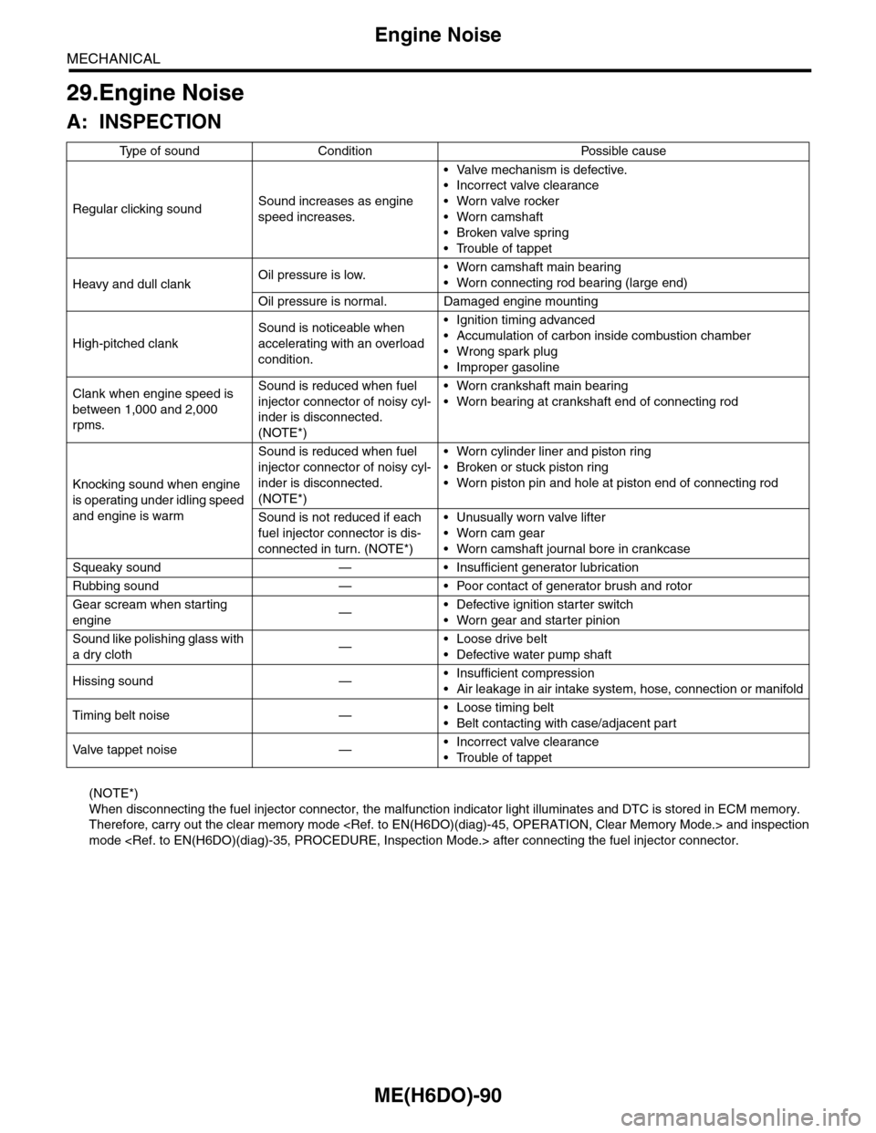
29.Engine Noise
A: INSPECTION
(NOTE*)
When disconnecting the fuel injector connector, the malfunction indicator light illuminates and DTC is stored in ECM memory.
Therefore, carry out the clear memory mode
mode
Ty p e o f s o u n d C o n d i t i o n P o s s i b l e c a u s e
Regular clicking soundSound increases as engine
speed increases.
•Valve mechanism is defective.
•Incorrect valve clearance
•Worn valve rocker
•Worn camshaft
•Broken valve spring
•Trouble of tappet
Heavy and dull clankOil pressure is low.•Worn camshaft main bearing
•Worn connecting rod bearing (large end)
Oil pressure is normal. Damaged engine mounting
High-pitched clank
Sound is noticeable when
accelerating with an overload
condition.
•Ignition timing advanced
•Accumulation of carbon inside combustion chamber
•Wrong spark plug
•Improper gasoline
Clank when engine speed is
between 1,000 and 2,000
rpms.
Sound is reduced when fuel
injector connector of noisy cyl-
inder is disconnected.
(NOTE*)
•Worn crankshaft main bearing
•Worn bearing at crankshaft end of connecting rod
Knocking sound when engine
is operating under idling speed
and engine is warm
Sound is reduced when fuel
injector connector of noisy cyl-
inder is disconnected.
(NOTE*)
•Worn cylinder liner and piston ring
•Broken or stuck piston ring
•Worn piston pin and hole at piston end of connecting rod
Sound is not reduced if each
fuel injector connector is dis-
connected in turn. (NOTE*)
•Unusually worn valve lifter
•Worn cam gear
•Worn camshaft journal bore in crankcase
Squeaky sound — • Insufficient generator lubrication
Rubbing sound — • Poor contact of generator brush and rotor
Gear scream when starting
engine—•Defective ignition starter switch
•Worn gear and starter pinion
Sound like polishing glass with
a dry cloth—•Loose drive belt
•Defective water pump shaft
Hissing sound —•Insufficient compression
•Air leakage in air intake system, hose, connection or manifold
Timing belt noise —•Loose timing belt
•Belt contacting with case/adjacent part
Va l ve t a p p e t n o i s e —•Incorrect valve clearance
•Trouble of tappet
Page 1960 of 2453
SC(H6DO)-2
General Description
STARTING/CHARGING SYSTEMS
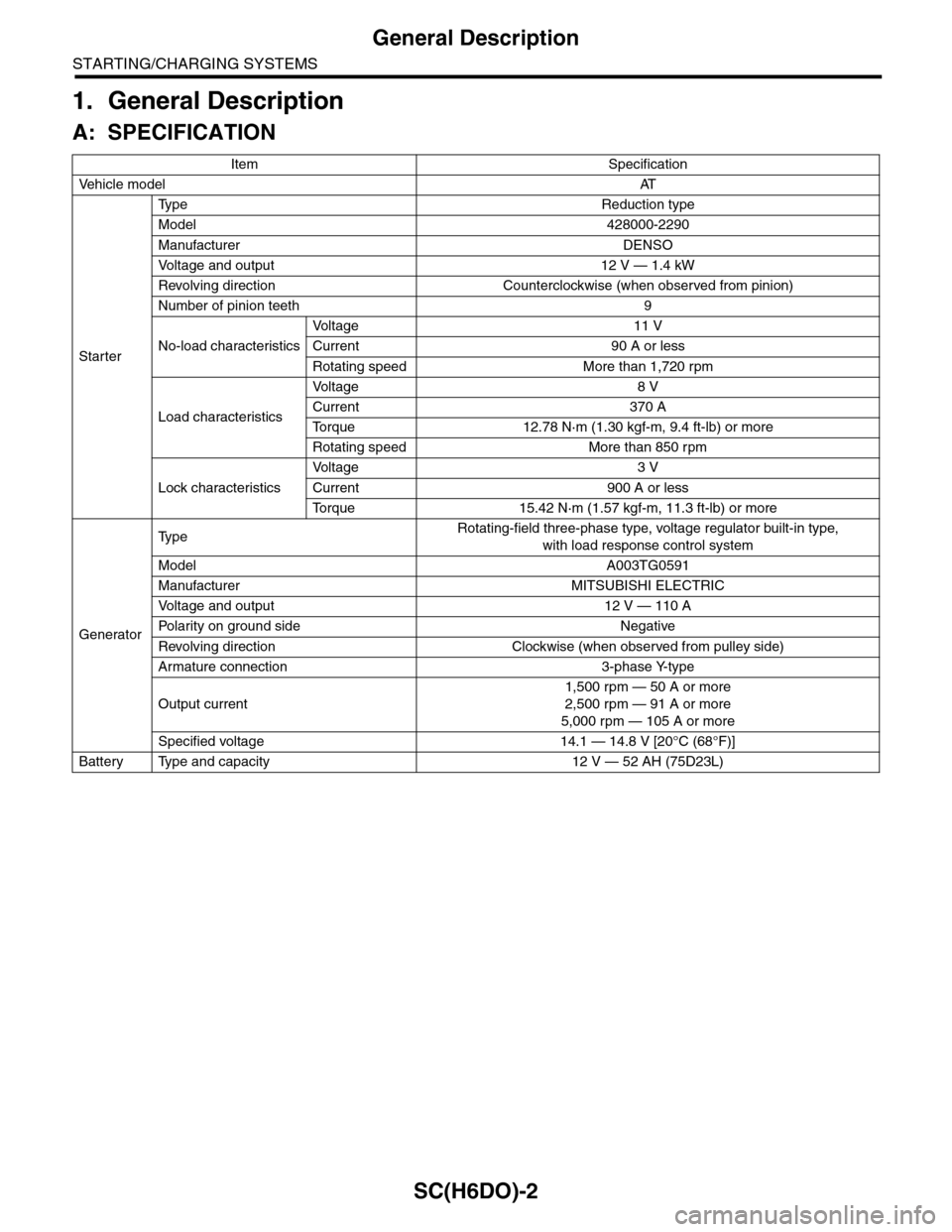
1. General Description
A: SPECIFICATION
Item Specification
Ve h i c l e m o d e lAT
Starter
Ty p e R e d u c t i o n t y p e
Model 428000-2290
Manufacturer DENSO
Vo l t a g e a n d o u t p u t 1 2 V — 1 . 4 k W
Revolving direction Counterclockwise (when observed from pinion)
Number of pinion teeth 9
No-load characteristics
Vo l t a g e 1 1 V
Current 90 A or less
Rotating speed More than 1,720 rpm
Load characteristics
Vo l t a g e 8 V
Current 370 A
To r q u e 1 2 . 7 8 N · m ( 1 . 3 0 k g f - m , 9 . 4 f t - l b ) o r m o r e
Rotating speed More than 850 rpm
Lock characteristics
Vo l t a g e 3 V
Current 900 A or less
To r q u e 1 5 . 4 2 N · m ( 1 . 5 7 k g f - m , 1 1 . 3 f t - l b ) o r m o r e
Generator
Ty p eRotating-field three-phase type, voltage regulator built-in type,
with load response control system
Model A003TG0591
Manufacturer MITSUBISHI ELECTRIC
Vo l t a g e a n d o u t p u t 1 2 V — 1 1 0 A
Po la r i t y on gr ou n d s id e N e g at i ve
Revolving direction Clockwise (when observed from pulley side)
Armature connection 3-phase Y-type
Output current
1,500 rpm — 50 A or more
2,500 rpm — 91 A or more
5,000 rpm — 105 A or more
Specified voltage 14.1 — 14.8 V [20°C (68°F)]
Battery Type and capacity 12 V — 52 AH (75D23L)