2009 SUBARU TRIBECA Starter
[x] Cancel search: StarterPage 2146 of 2453
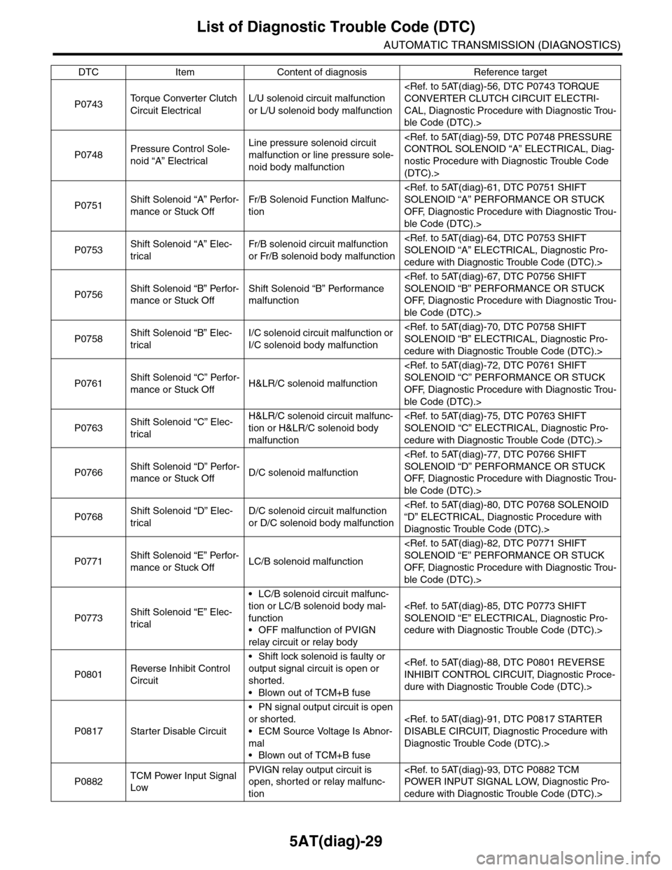
5AT(diag)-29
List of Diagnostic Trouble Code (DTC)
AUTOMATIC TRANSMISSION (DIAGNOSTICS)
P0743To r q u e C o n v e r t e r C l u t c h
Circuit Electrical
L/U solenoid circuit malfunction
or L/U solenoid body malfunction
CAL, Diagnostic Procedure with Diagnostic Trou-
ble Code (DTC).>
P0748Pressure Control Sole-
noid “A” Electrical
Line pressure solenoid circuit
malfunction or line pressure sole-
noid body malfunction
nostic Procedure with Diagnostic Trouble Code
(DTC).>
P0751Shift Solenoid “A” Perfor-
mance or Stuck Off
Fr/B Solenoid Function Malfunc-
tion
OFF, Diagnostic Procedure with Diagnostic Trou-
ble Code (DTC).>
P0753Shift Solenoid “A” Elec-
trical
Fr/B solenoid circuit malfunction
or Fr/B solenoid body malfunction
cedure with Diagnostic Trouble Code (DTC).>
P0756Shift Solenoid “B” Perfor-
mance or Stuck Off
Shift Solenoid “B” Performance
malfunction
OFF, Diagnostic Procedure with Diagnostic Trou-
ble Code (DTC).>
P0758Shift Solenoid “B” Elec-
trical
I/C solenoid circuit malfunction or
I/C solenoid body malfunction
cedure with Diagnostic Trouble Code (DTC).>
P0761Shift Solenoid “C” Perfor-
mance or Stuck OffH&LR/C solenoid malfunction
OFF, Diagnostic Procedure with Diagnostic Trou-
ble Code (DTC).>
P0763Shift Solenoid “C” Elec-
trical
H&LR/C solenoid circuit malfunc-
tion or H&LR/C solenoid body
malfunction
cedure with Diagnostic Trouble Code (DTC).>
P0766Shift Solenoid “D” Perfor-
mance or Stuck OffD/C solenoid malfunction
OFF, Diagnostic Procedure with Diagnostic Trou-
ble Code (DTC).>
P0768Shift Solenoid “D” Elec-
trical
D/C solenoid circuit malfunction
or D/C solenoid body malfunction
Diagnostic Trouble Code (DTC).>
P0771Shift Solenoid “E” Perfor-
mance or Stuck OffLC/B solenoid malfunction
OFF, Diagnostic Procedure with Diagnostic Trou-
ble Code (DTC).>
P0773Shift Solenoid “E” Elec-
trical
•LC/B solenoid circuit malfunc-
tion or LC/B solenoid body mal-
function
•OFF malfunction of PVIGN
relay circuit or relay body
cedure with Diagnostic Trouble Code (DTC).>
P0801Reverse Inhibit Control
Circuit
•Shift lock solenoid is faulty or
output signal circuit is open or
shorted.
•Blown out of TCM+B fuse
dure with Diagnostic Trouble Code (DTC).>
P0817 Starter Disable Circuit
•PN signal output circuit is open
or shorted.
•ECM Source Voltage Is Abnor-
mal
•Blown out of TCM+B fuse
Diagnostic Trouble Code (DTC).>
P0882TCM Power Input Signal
Low
PVIGN relay output circuit is
open, shorted or relay malfunc-
tion
cedure with Diagnostic Trouble Code (DTC).>
DTC Item Content of diagnosis Reference target
Page 2208 of 2453
5AT(diag)-91
Diagnostic Procedure with Diagnostic Trouble Code (DTC)
AUTOMATIC TRANSMISSION (DIAGNOSTICS)
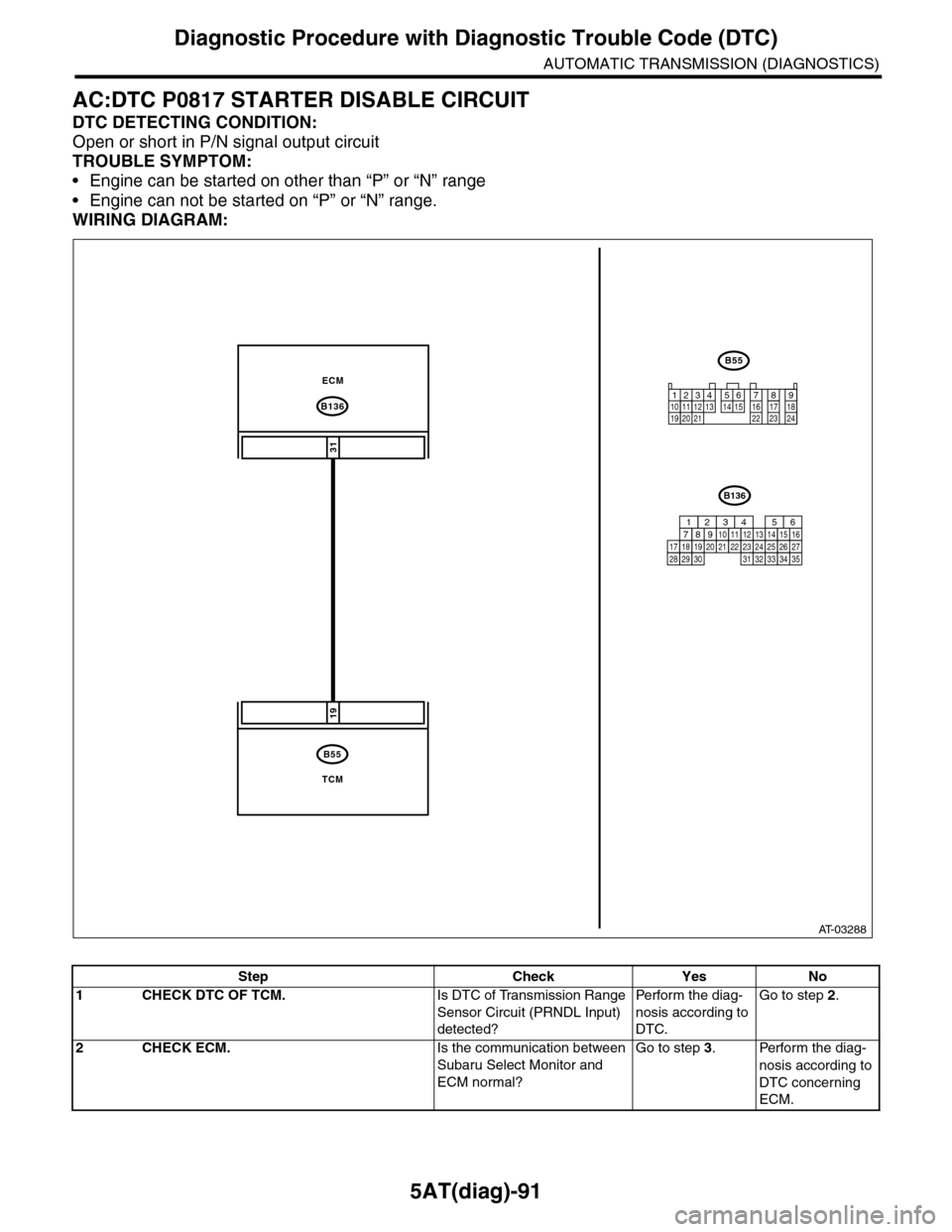
AC:DTC P0817 STARTER DISABLE CIRCUIT
DTC DETECTING CONDITION:
Open or short in P/N signal output circuit
TROUBLE SYMPTOM:
•Engine can be started on other than “P” or “N” range
•Engine can not be started on “P” or “N” range.
WIRING DIAGRAM:
AT-03288
B136
B55
31
19
ECM
TCM
B55
12341011 121920 21135614 1578916 17 1822 23 24
B136
16101112131415252430
9871718192028212223293231
123456
2726333435
Step Check Yes No
1CHECK DTC OF TCM.Is DTC of Transmission Range
Sensor Circuit (PRNDL Input)
detected?
Pe r for m t h e d ia g -
nosis according to
DTC.
Go to step 2.
2CHECK ECM.Is the communication between
Subaru Select Monitor and
ECM normal?
Go to step 3.Perform the diag-
nosis according to
DTC concerning
ECM.
Page 2251 of 2453
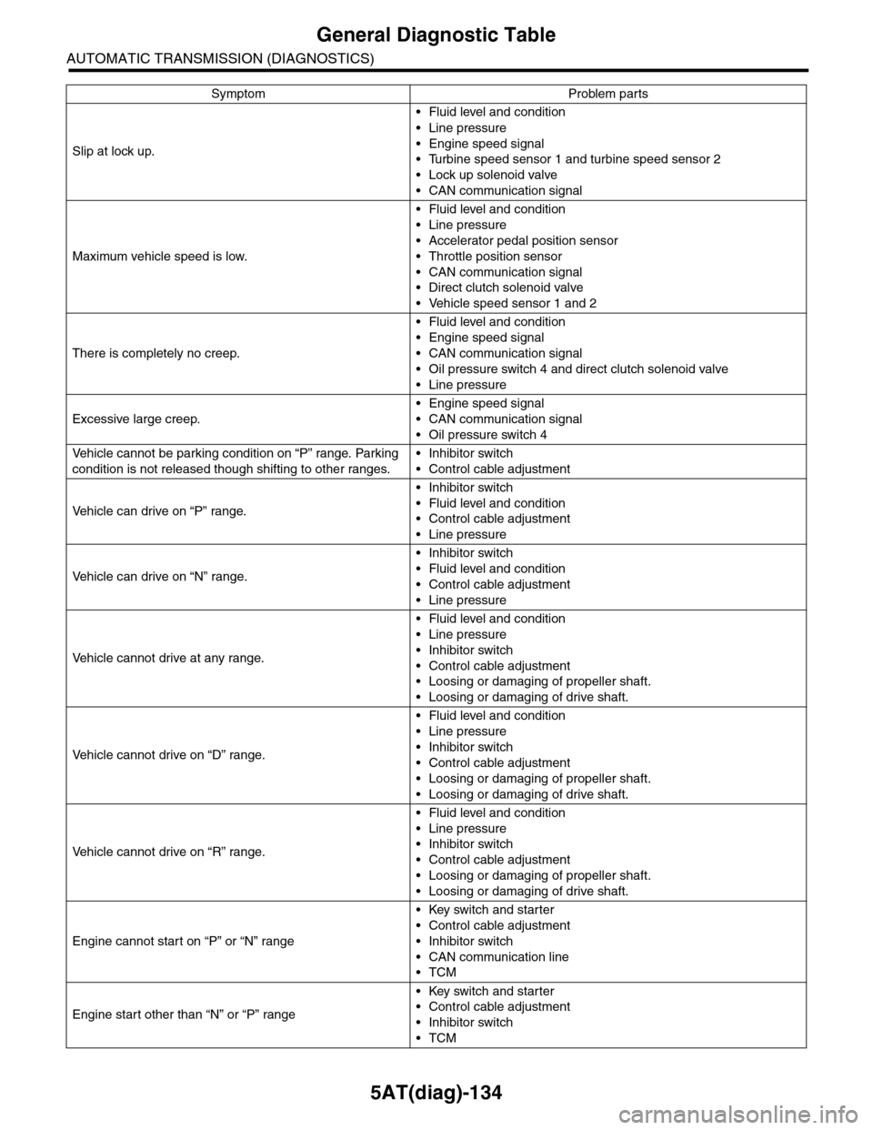
5AT(diag)-134
General Diagnostic Table
AUTOMATIC TRANSMISSION (DIAGNOSTICS)
Slip at lock up.
•Fluid level and condition
•Line pressure
•Engine speed signal
•Turbine speed sensor 1 and turbine speed sensor 2
•Lock up solenoid valve
•CAN communication signal
Maximum vehicle speed is low.
•Fluid level and condition
•Line pressure
•Accelerator pedal position sensor
•Throttle position sensor
•CAN communication signal
•Direct clutch solenoid valve
•Vehicle speed sensor 1 and 2
There is completely no creep.
•Fluid level and condition
•Engine speed signal
•CAN communication signal
•Oil pressure switch 4 and direct clutch solenoid valve
•Line pressure
Excessive large creep.
•Engine speed signal
•CAN communication signal
•Oil pressure switch 4
Ve h i c l e c a n n o t b e p a r k i n g c o n d i t i o n o n “ P ” r a n g e . Pa r k i n g
condition is not released though shifting to other ranges.
•Inhibitor switch
•Control cable adjustment
Ve h i c l e c a n d r i v e o n “ P ” r a n g e .
•Inhibitor switch
•Fluid level and condition
•Control cable adjustment
•Line pressure
Ve h i c l e c a n d r i v e o n “ N ” r a n g e .
•Inhibitor switch
•Fluid level and condition
•Control cable adjustment
•Line pressure
Ve h i c l e c a n n o t d r i v e a t a n y r a n g e .
•Fluid level and condition
•Line pressure
•Inhibitor switch
•Control cable adjustment
•Loosing or damaging of propeller shaft.
•Loosing or damaging of drive shaft.
Ve h i c l e c a n n o t d r i v e o n “ D ” r a n g e .
•Fluid level and condition
•Line pressure
•Inhibitor switch
•Control cable adjustment
•Loosing or damaging of propeller shaft.
•Loosing or damaging of drive shaft.
Ve h i c l e c a n n o t d r i v e o n “ R ” r a n g e .
•Fluid level and condition
•Line pressure
•Inhibitor switch
•Control cable adjustment
•Loosing or damaging of propeller shaft.
•Loosing or damaging of drive shaft.
Engine cannot start on “P” or “N” range
•Key switch and starter
•Control cable adjustment
•Inhibitor switch
•CAN communication line
•TCM
Engine start other than “N” or “P” range
•Key switch and starter
•Control cable adjustment
•Inhibitor switch
•TCM
Symptom Problem parts
Page 2279 of 2453
CS-27
Select Cable
CONTROL SYSTEMS
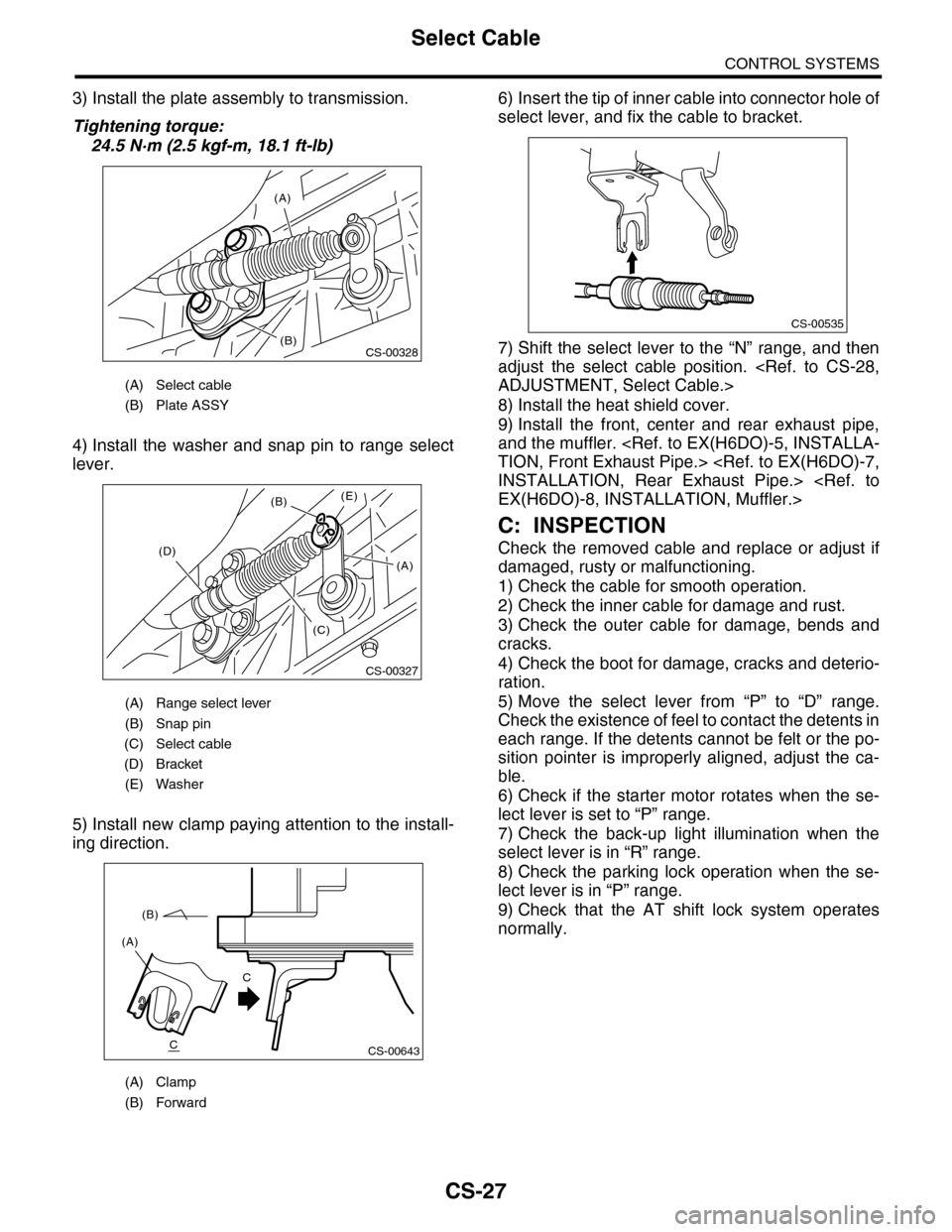
3) Install the plate assembly to transmission.
Tightening torque:
24.5 N·m (2.5 kgf-m, 18.1 ft-lb)
4) Install the washer and snap pin to range select
lever.
5) Install new clamp paying attention to the install-
ing direction.
6) Insert the tip of inner cable into connector hole of
select lever, and fix the cable to bracket.
7) Shift the select lever to the “N” range, and then
adjust the select cable position.
8) Install the heat shield cover.
9) Install the front, center and rear exhaust pipe,
and the muffler.
C: INSPECTION
Check the removed cable and replace or adjust if
damaged, rusty or malfunctioning.
1) Check the cable for smooth operation.
2) Check the inner cable for damage and rust.
3) Check the outer cable for damage, bends and
cracks.
4) Check the boot for damage, cracks and deterio-
ration.
5) Move the select lever from “P” to “D” range.
Check the existence of feel to contact the detents in
each range. If the detents cannot be felt or the po-
sition pointer is improperly aligned, adjust the ca-
ble.
6) Check if the starter motor rotates when the se-
lect lever is set to “P” range.
7) Check the back-up light illumination when the
select lever is in “R” range.
8) Check the parking lock operation when the se-
lect lever is in “P” range.
9) Check that the AT shift lock system operates
normally.
(A) Select cable
(B) Plate ASSY
(A) Range select lever
(B) Snap pin
(C) Select cable
(D) Bracket
(E) Washer
(A) Clamp
(B) Forward
(A)
(B)CS-00328
CS-00327
(B)
(D)
(C)
(E)
(A)
CS-00643
(A)
(B)
C
C
CS-00535
Page 2285 of 2453
CS-33
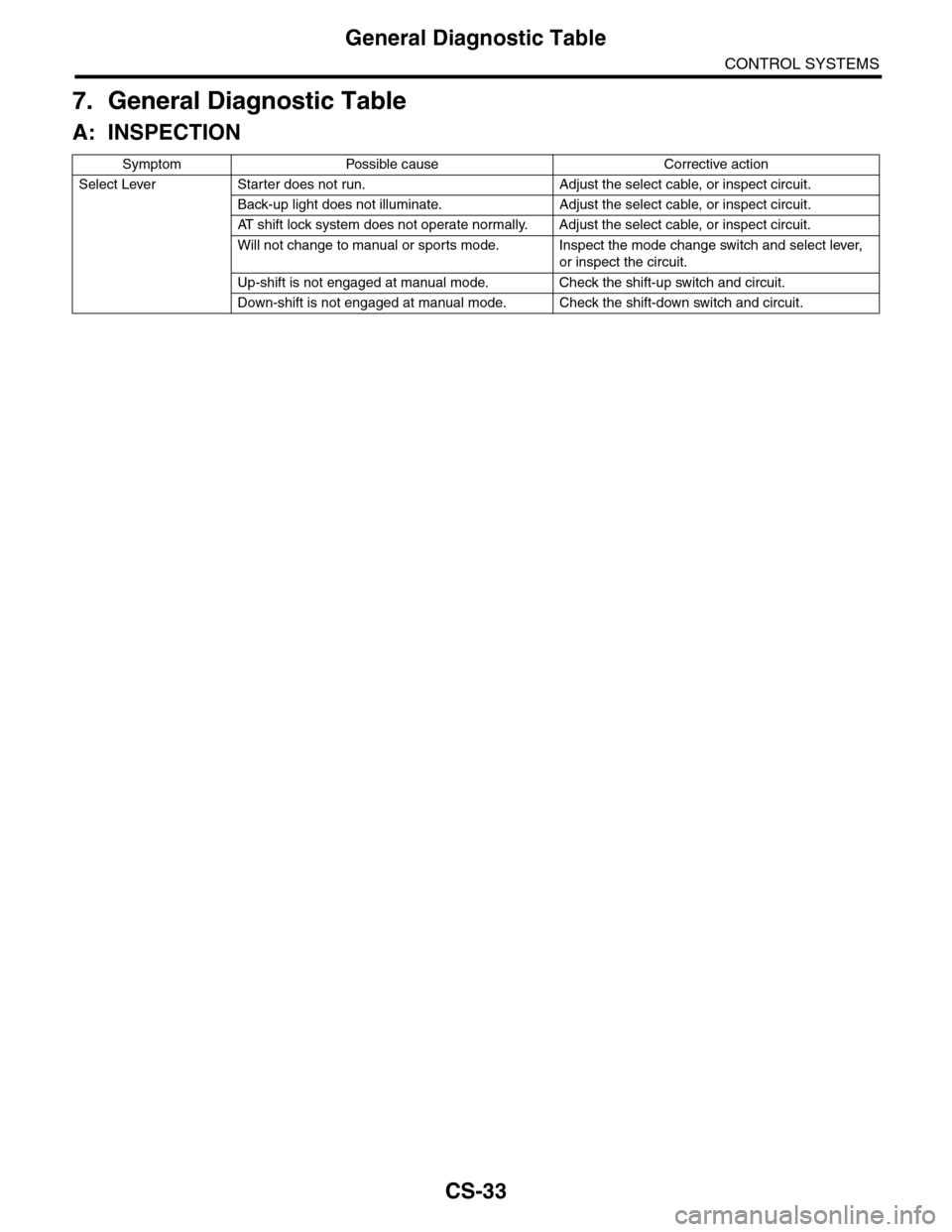
General Diagnostic Table
CONTROL SYSTEMS
7. General Diagnostic Table
A: INSPECTION
Symptom Possible cause Corrective action
Select Lever Starter does not run. Adjust the select cable, or inspect circuit.
Back-up light does not illuminate. Adjust the select cable, or inspect circuit.
AT s h i f t l o c k s y s t e m d o e s n o t o p e r a t e n o r m a l l y. A d j u s t t h e s e l e c t c a b l e , o r i n s p e c t c i r c u i t .
Will not change to manual or sports mode. Inspect the mode change switch and select lever,
or inspect the circuit.
Up-shift is not engaged at manual mode. Check the shift-up switch and circuit.
Down-shift is not engaged at manual mode. Check the shift-down switch and circuit.
Page 2297 of 2453
WI-13
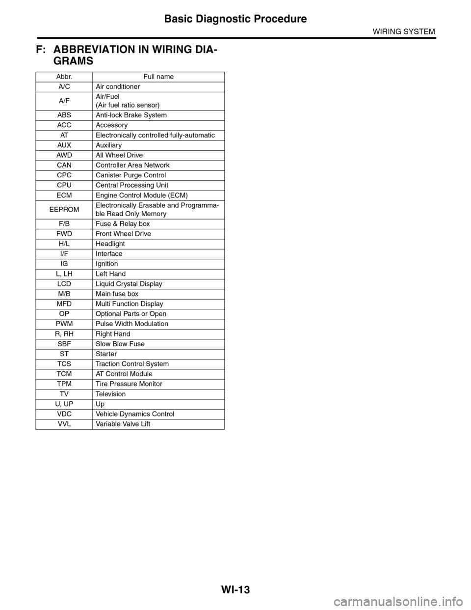
Basic Diagnostic Procedure
WIRING SYSTEM
F: ABBREVIATION IN WIRING DIA-
GRAMS
Abbr. Full name
A/C Air conditioner
A/FAir/Fuel
(Air fuel ratio sensor)
ABS Anti-lock Brake System
ACC Accessor y
AT E l e c t r o n i c a l l y c o n t r o l l e d f u l l y - a u t o m a t i c
AUX Auxiliar y
AW D A ll W he e l D r i ve
CAN Controller Area Network
CPC Canister Purge Control
CPU Central Processing Unit
ECM Engine Control Module (ECM)
EEPROMElectronically Erasable and Programma-
ble Read Only Memory
F/B Fuse & Relay box
FWD Front Wheel Drive
H/L Headlight
I/F Interface
IG Ignition
L, LH Left Hand
LCD Liquid Crystal Display
M/B Main fuse box
MFD Multi Function Display
OP Optional Parts or Open
PWM Pulse Width Modulation
R, RH Right Hand
SBF Slow Blow Fuse
ST Starter
TCS Traction Control System
TCM AT Control Module
TPM Tire Pressure Monitor
TV Television
U, UP Up
VDC Vehicle Dynamics Control
VVL Variable Valve Lift
Page 2305 of 2453
WI-21
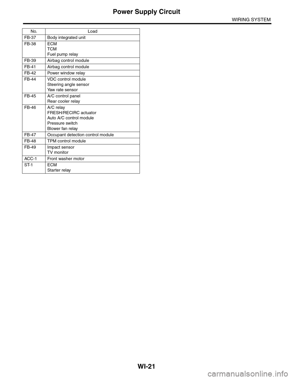
Power Supply Circuit
WIRING SYSTEM
FB-37 Body integrated unit
FB-38 ECM
TCM
Fuel pump relay
FB-39 Airbag control module
FB-41 Airbag control module
FB-42 Power window relay
FB-44 VDC control module
Steering angle sensor
Ya w r a t e s e n s o r
FB-45 A/C control panel
Rear cooler relay
FB-46 A/C relay
FRESH/RECIRC actuator
Auto A/C control module
Pressure switch
Blower fan relay
FB-47 Occupant detection control module
FB-48 TPM control module
FB-49 Impact sensor
TV monitor
ACC -1 Front washer motor
ST-1 ECM
Starter relay
No. Load
Page 2316 of 2453
WI-32
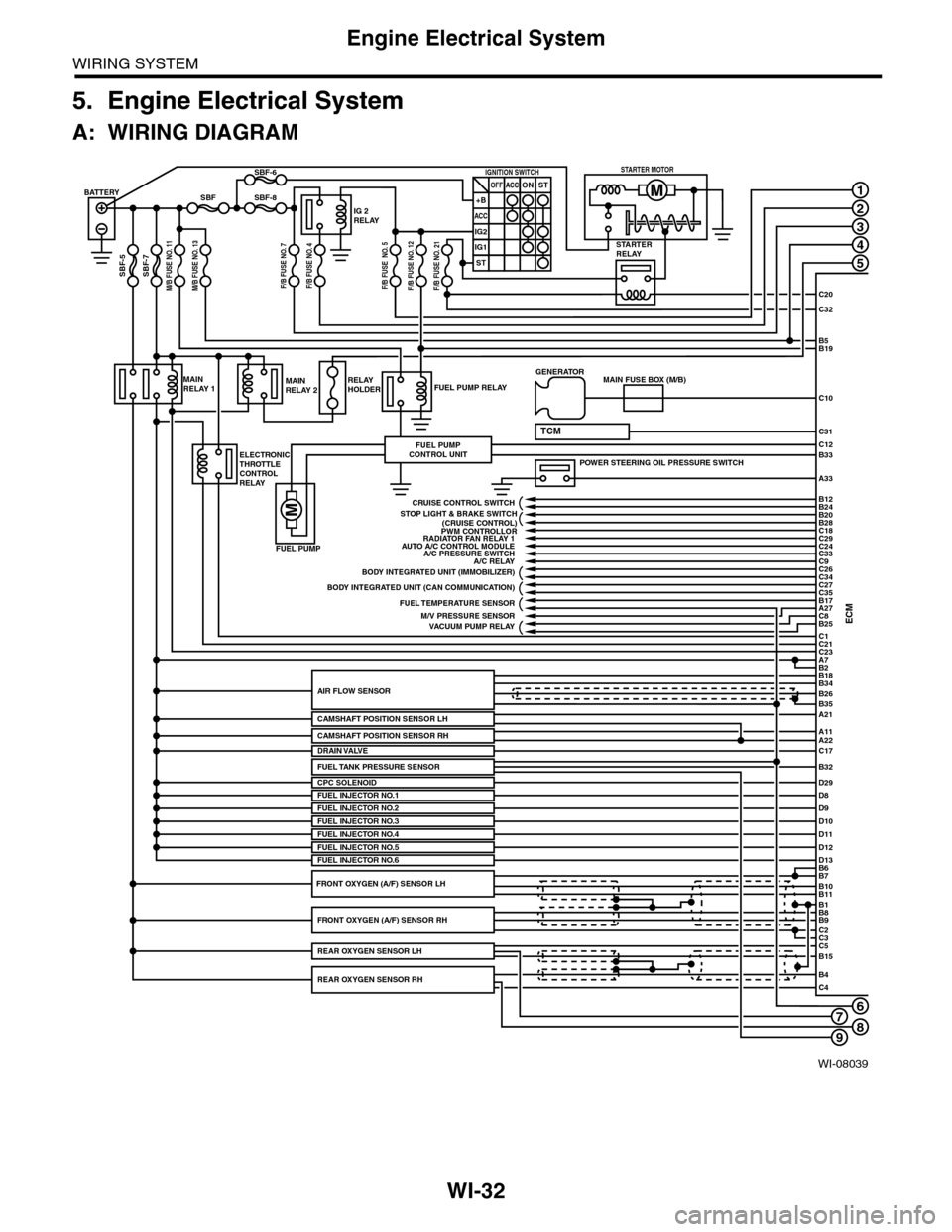
Engine Electrical System
WIRING SYSTEM
5. Engine Electrical System
A: WIRING DIAGRAM
WI-08039
678
1
2
3
4
5
C20
C32
C31
B5B19
B33
A33
C10
ECMC1B25C8A27
C21C23A7
D29
B2
BATTERY
M/B FUSE NO. 11SBF-7
SBF
SBF-5
SBF-8
SBF-6
STARTERRELAY
IG 2RELAY
IGNITION SWITCHOFF+B
ACC
IG2
IG1
ACCONST
ST
STARTER MOTOR
MAINRELAY 1
ELECTRONICTHROTTLECONTROLRELAY
FUEL PUMP RELAY
FUEL PUMP
FUEL PUMPCONTROL UNIT
MAINRELAY 2RELAYHOLDER
A21
A11A22
B34
B35
B7B6
B11B10
B9B8
C2
B26AIR FLOW SENSOR
CAMSHAFT POSITION SENSOR LH
CPC SOLENOID
B1
C3C5B15
B4C4
POWER STEERING OIL PRESSURE SWITCH
C12
MAIN FUSE BOX (M/B)GENERATOR
B18
TCM
D8FUEL INJECTOR NO.1D9D10D11
PWM CONTROLLORAUTO A/C CONTROL MODULE
A/C RELAY
BODY INTEGRATED UNIT (CAN COMMUNICATION)
FUEL TEMPERATURE SENSOR
VACUUM PUMP RELAY
BODY INTEGRATED UNIT (IMMOBILIZER)
C18C29C24C33
C27
B24B12
B20B28
C26C34
C35B17
CRUISE CONTROL SWITCH
FUEL INJECTOR NO.2FUEL INJECTOR NO.3
C17DRAIN VALVE
FUEL INJECTOR NO.4D12D13FUEL INJECTOR NO.5FUEL INJECTOR NO.6
FRONT OXYGEN (A/F) SENSOR RH
REAR OXYGEN SENSOR RH
REAR OXYGEN SENSOR LH
FRONT OXYGEN (A/F) SENSOR LH
A/C PRESSURE SWITCH
M/V PRESSURE SENSOR
RADIATOR FAN RELAY 1
STOP LIGHT & BRAKE SWITCH(CRUISE CONTROL)
C9
FUEL TANK PRESSURE SENSORB32
M/B FUSE NO. 13F/B FUSE NO. 7F/B FUSE NO. 4F/B FUSE NO. 5F/B FUSE NO. 12F/B FUSE NO. 21
CAMSHAFT POSITION SENSOR RH
9