Page 1476 of 2453
EN(H6DO)(diag)-315
Diagnostic Procedure with Diagnostic Trouble Code (DTC)
ENGINE (DIAGNOSTICS)
DK:DTC P1518 STARTER SWITCH CIRCUIT LOW INPUT
DTC DETECTING CONDITION:
•Immediately at fault recognition
•GENERAL DESCRIPTION
PUT, Diagnostic Trouble Code (DTC) Detecting Criteria.>
TROUBLE SYMPTOM:
Failure of engine to start
CAUTION:
After repair or replacement of faulty parts, perform Clear Memory Mode
OPERATION, Clear Memory Mode.> and Inspection Mode
Inspection Mode.>.
Page 1477 of 2453
EN(H6DO)(diag)-316
Diagnostic Procedure with Diagnostic Trouble Code (DTC)
ENGINE (DIAGNOSTICS)
WIRING DIAGRAM:
EN-03735
3220
NO.21
B225
MAIN SBFSBF-6
E
1513
1614
ECM
B136
B72
B14
M
23
B72B225
101112
131415 16
17181920
21222324
25262728
293031 32
333435 36 39 40
3738
129
34
56
78
134562
BATTERY
IGNITIONSWITCH
STARTERRELAYSTARTER MOTOR
B136
16101112131415252430
9871718192028212223293231
123456
2726333435
Page 1478 of 2453
EN(H6DO)(diag)-317
Diagnostic Procedure with Diagnostic Trouble Code (DTC)
ENGINE (DIAGNOSTICS)
Step Check Yes No
1CHECK OPERATION OF STARTER MOTOR.
Place the inhibitor switch in “P” or “N” range.
Does the starter motor operate
when ignition switch is turned
to START?
Repair the har-
ness and connec-
tor.
NOTE:In this case, repair
the following item:
•Open or
ground short
circuit of har-
ness between
ECM and start-
er motor con-
nector
•Poor contact
in ECM connec-
tor
Check the starter
motor circuit.
to
EN(H6DO)(diag)-
58, STARTER
MOTOR CIRCUIT,
Diagnostics for
Engine Starting
Fai lu r e.>
Page 1618 of 2453

GD(H6DO)-6
List of Diagnostic Trouble Code (DTC)
GENERAL DESCRIPTION
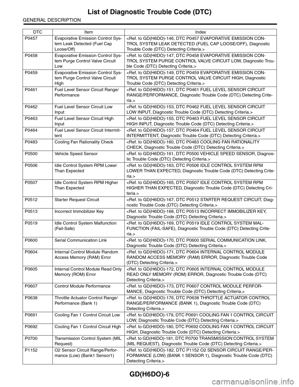
P0457 Evaporative Emission Control Sys-
tem Leak Detected (Fuel Cap
Loose/Off)
TROL SYSTEM LEAK DETECTED (FUEL CAP LOOSE/OFF), Diagnostic
Tr o u b l e C o d e ( D T C ) D e t e c t i n g C r i t e r i a . >
P0458 Evaporative Emission Control Sys-
tem Purge Control Valve Circuit
Low
TROL SYSTEM PURGE CONTROL VALVE CIRCUIT LOW, Diagnostic Trou-
ble Code (DTC) Detecting Criteria.>
P0459 Evaporative Emission Control Sys-
tem Purge Control Valve Circuit
High
TROL SYSTEM PURGE CONTROL VALVE CIRCUIT HIGH, Diagnostic
Tr o u b l e C o d e ( D T C ) D e t e c t i n g C r i t e r i a . >
P0461 Fuel Level Sensor Circuit Range/
Per fo r m an ce
RANGE/PERFORMANCE, Diagnostic Trouble Code (DTC) Detecting Crite-
ria.>
P0462 Fuel Level Sensor Circuit Low
Input
LOW INPUT, Diagnostic Trouble Code (DTC) Detecting Criteria.>
P0463 Fuel Level Sensor Circuit High
Input
HIGH INPUT, Diagnostic Trouble Code (DTC) Detecting Criteria.>
P0464 Fuel Level Sensor Circuit Intermit-
tent
INTERMITTENT, Diagnostic Trouble Code (DTC) Detecting Criteria.>
P0483 Cooling Fan Rationality Check
CHECK, Diagnostic Trouble Code (DTC) Detecting Criteria.>
P0500 Vehicle Speed Sensor
tic Trouble Code (DTC) Detecting Criteria.>
P0506 Idle Control System RPM Lower
Than Expected
LOWER THAN EXPECTED, Diagnostic Trouble Code (DTC) Detecting Crite-
ria.>
P0507 Idle Control System RPM Higher
Than Expected
HIGHER THAN EXPECTED, Diagnostic Trouble Code (DTC) Detecting Cri-
teria.>
P0512 Starter Request Circuit
nostic Trouble Code (DTC) Detecting Criteria.>
P0513 Incorrect Immobilizer Key
Diagnostic Trouble Code (DTC) Detecting Criteria.>
P0519 Idle Control System Malfunction
(Fail-Safe)
FUNCTION (FAIL-SAFE), Diagnostic Trouble Code (DTC) Detecting Crite-
ria.>
P0600 Serial Communication Link
Diagnostic Trouble Code (DTC) Detecting Criteria.>
P0604 Internal Control Module Random
Access Memory (RAM) Error
RANDOM ACCESS MEMORY (RAM) ERROR, Diagnostic Trouble Code
(DTC) Detecting Criteria.>
P0605 Internal Control Module Read Only
Memory (ROM) Error
READ ONLY MEMORY (ROM) ERROR, Diagnostic Trouble Code (DTC)
Detecting Criteria.>
P0607 Control Module Performance
MANCE, Diagnostic Trouble Code (DTC) Detecting Criteria.>
P0638 Throttle Actuator Control Range/
Per fo r m an ce ( B an k 1 )
RANGE/PERFORMANCE (BANK 1), Diagnostic Trouble Code (DTC)
Detecting Criteria.>
P0691 Cooling Fan 1 Control Circuit Low
LOW, Diagnostic Trouble Code (DTC) Detecting Criteria.>
P0692 Cooling Fan 1 Control Circuit High
HIGH, Diagnostic Trouble Code (DTC) Detecting Criteria.>
P0700 Transmission Control System (MIL
Request)
(MIL REQUEST), Diagnostic Trouble Code (DTC) Detecting Criteria.>
P1152 O2 Sensor Circuit Range/Perfor-
mance (Low) (Bank1 Sensor1)
FORMANCE (LOW) (BANK 1 SENSOR 1), Diagnostic Trouble Code (DTC)
Detecting Criteria.>
DTC Item Index
Page 1619 of 2453

GD(H6DO)-7
List of Diagnostic Trouble Code (DTC)
GENERAL DESCRIPTION
P1153 O2 Sensor Circuit Range/Perfor-
mance (High) (Bank1 Sensor1)
FORMANCE (HIGH) (BANK 1 SENSOR 1), Diagnostic Trouble Code (DTC)
Detecting Criteria.>
P1154 O2 Sensor Circuit Range/Perfor-
mance (Low) (Bank 2 Sensor 1)
FORMANCE (LOW) (BANK 2 SENSOR 1), Diagnostic Trouble Code (DTC)
Detecting Criteria.>
P1155 O2 Sensor Circuit Range/Perfor-
mance (High) (Bank 2 Sensor 1)
FORMANCE (HIGH) (BANK 2 SENSOR 1), Diagnostic Trouble Code (DTC)
Detecting Criteria.>
P1160 Return Spring Failure
nostic Trouble Code (DTC) Detecting Criteria.>
P1443 Vent Control Solenoid Valve Func-
tion Problem
FUNCTION PROBLEM, Diagnostic Trouble Code (DTC) Detecting Criteria.>
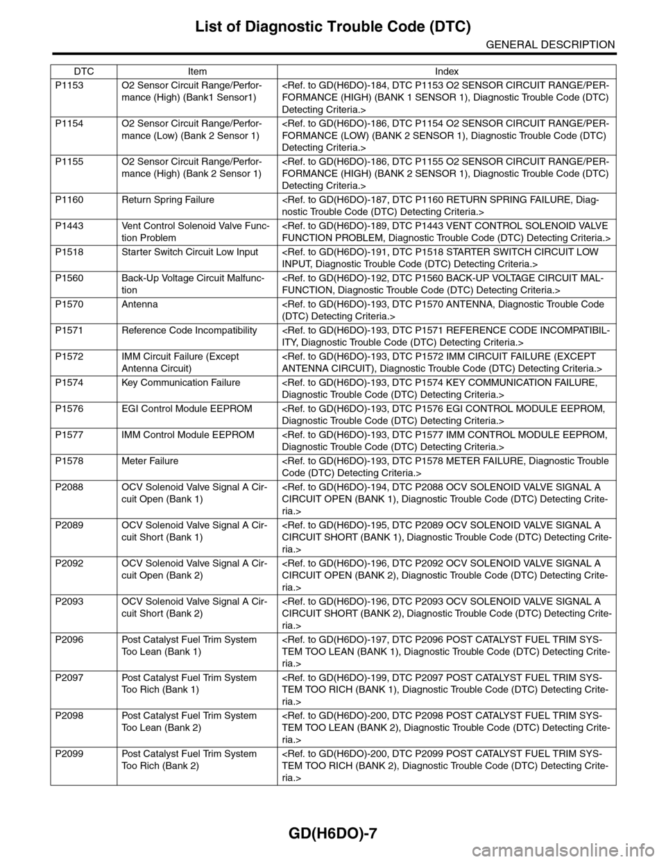
P1518 Starter Switch Circuit Low Input
INPUT, Diagnostic Trouble Code (DTC) Detecting Criteria.>
P1560 Back-Up Voltage Circuit Malfunc-
tion
FUNCTION, Diagnostic Trouble Code (DTC) Detecting Criteria.>
P1570 Antenna
(DTC) Detecting Criteria.>
P1571 Reference Code Incompatibility
ITY, Diagnostic Trouble Code (DTC) Detecting Criteria.>
P1572 IMM Circuit Failure (Except
Antenna Circuit)
ANTENNA CIRCUIT), Diagnostic Trouble Code (DTC) Detecting Criteria.>
P1574 Key Communication Failure
Diagnostic Trouble Code (DTC) Detecting Criteria.>
P1576 EGI Control Module EEPROM
Diagnostic Trouble Code (DTC) Detecting Criteria.>
P1577 IMM Control Module EEPROM
Diagnostic Trouble Code (DTC) Detecting Criteria.>
P1578 Meter Failure
Code (DTC) Detecting Criteria.>
P2088 OCV Solenoid Valve Signal A Cir-
cuit Open (Bank 1)
CIRCUIT OPEN (BANK 1), Diagnostic Trouble Code (DTC) Detecting Crite-
ria.>
P2089 OCV Solenoid Valve Signal A Cir-
cuit Short (Bank 1)
CIRCUIT SHORT (BANK 1), Diagnostic Trouble Code (DTC) Detecting Crite-
ria.>
P2092 OCV Solenoid Valve Signal A Cir-
cuit Open (Bank 2)
CIRCUIT OPEN (BANK 2), Diagnostic Trouble Code (DTC) Detecting Crite-
ria.>
P2093 OCV Solenoid Valve Signal A Cir-
cuit Short (Bank 2)
CIRCUIT SHORT (BANK 2), Diagnostic Trouble Code (DTC) Detecting Crite-
ria.>
P2096 Post Catalyst Fuel Trim System
To o L e a n ( B a n k 1 )
TEM TOO LEAN (BANK 1), Diagnostic Trouble Code (DTC) Detecting Crite-
ria.>
P2097 Post Catalyst Fuel Trim System
To o R i c h ( B a n k 1 )
TEM TOO RICH (BANK 1), Diagnostic Trouble Code (DTC) Detecting Crite-
ria.>
P2098 Post Catalyst Fuel Trim System
To o L e a n ( B a n k 2 )
TEM TOO LEAN (BANK 2), Diagnostic Trouble Code (DTC) Detecting Crite-
ria.>
P2099 Post Catalyst Fuel Trim System
To o R i c h ( B a n k 2 )
TEM TOO RICH (BANK 2), Diagnostic Trouble Code (DTC) Detecting Crite-
ria.>
DTC Item Index
Page 1726 of 2453
GD(H6DO)-114
Diagnostic Trouble Code (DTC) Detecting Criteria
GENERAL DESCRIPTION
BX:DTC P0335 CRANKSHAFT POSITION SENSOR “A” CIRCUIT
1. OUTLINE OF DIAGNOSIS
Detect the open or short circuit of the crankshaft position sensor.
Judge as NG when the crank signal is not input even though the starter was rotated.
2. COMPONENT DESCRIPTION
3. ENABLE CONDITIONS
(A) Camshaft signal (RH) (B) Camshaft signal (LH) (C) Crankshaft signal
(1) Crankshaft position sensor (2) Crank sprocket (3) Crankshaft half-turn
Secondary Parameters Enable Conditions
None
(A)
(C)#6BTDC10 CA#3BTDC10 CA#2BTDC10 CA#5BTDC10 CA#4BTDC10 CA
10 CA30 CA30 CA
#1BTDC10 CA#1BTDC10 CA
EN-03092
(B)
2 ENGINE ROTATION AND 3 CAMSHAFT POSITION SENSOR SIGNALS BETWEEN 0 CA - 0 CA IS NORMAL
EN-02188
( 1 )
( 2 )
( 3 )
Page 1727 of 2453

GD(H6DO)-115
Diagnostic Trouble Code (DTC) Detecting Criteria
GENERAL DESCRIPTION
4. GENERAL DRIVING CYCLE
Always perform the diagnosis continuously.
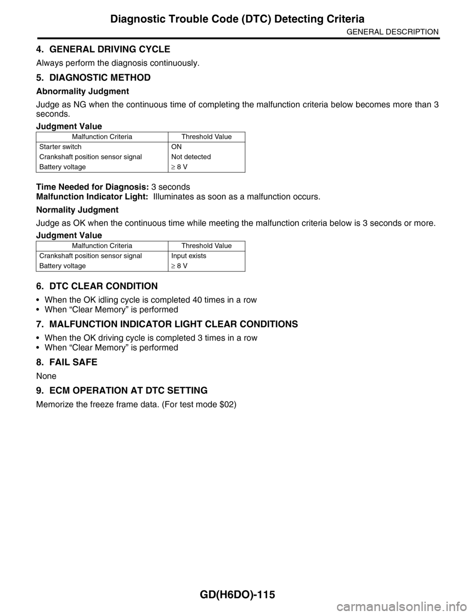
5. DIAGNOSTIC METHOD
Abnormality Judgment
Judge as NG when the continuous time of completing the malfunction criteria below becomes more than 3
seconds.
Time Needed for Diagnosis: 3 seconds
Malfunction Indicator Light: Illuminates as soon as a malfunction occurs.
Normality Judgment
Judge as OK when the continuous time while meeting the malfunction criteria below is 3 seconds or more.
6. DTC CLEAR CONDITION
•When the OK idling cycle is completed 40 times in a row
•When “Clear Memory” is performed
7. MALFUNCTION INDICATOR LIGHT CLEAR CONDITIONS
•When the OK driving cycle is completed 3 times in a row
•When “Clear Memory” is performed
8. FAIL SAFE
None
9. ECM OPERATION AT DTC SETTING
Memorize the freeze frame data. (For test mode $02)
Judgment Value
Malfunction Criteria Threshold Value
Starter switch ON
Crankshaft position sensor signal Not detected
Battery voltage≥ 8 V
Judgment Value
Malfunction Criteria Threshold Value
Crankshaft position sensor signal Input exists
Battery voltage≥ 8 V
Page 1779 of 2453

GD(H6DO)-167
Diagnostic Trouble Code (DTC) Detecting Criteria
GENERAL DESCRIPTION
CU:DTC P0512 STARTER REQUEST CIRCUIT
1. OUTLINE OF DIAGNOSIS
Detect the open or short circuit of starter SW.
Judge ON NG when the starter SW signal remains on.
2. ENABLE CONDITIONS
3. GENERAL DRIVING CYCLE
Always perform the diagnosis continuously.
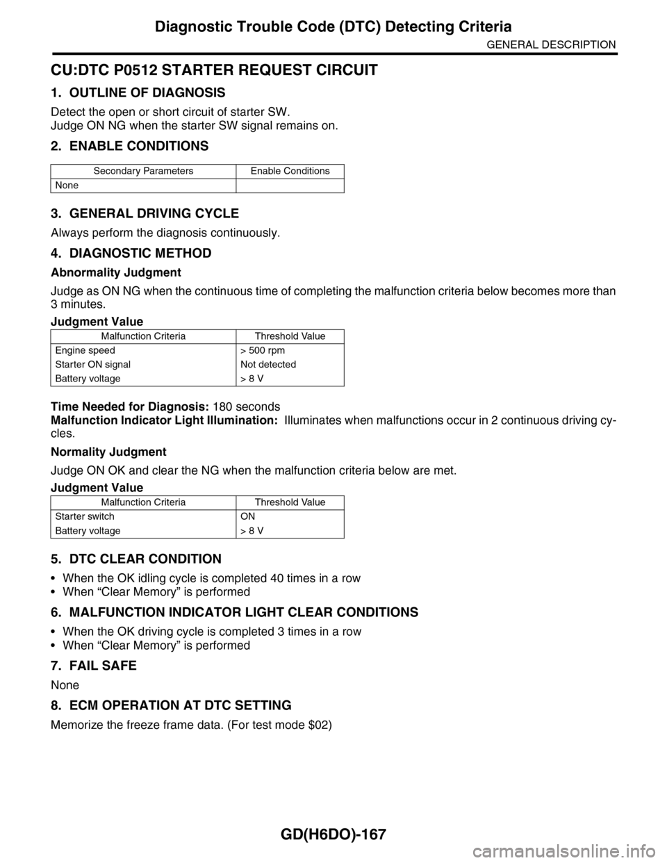
4. DIAGNOSTIC METHOD
Abnormality Judgment
Judge as ON NG when the continuous time of completing the malfunction criteria below becomes more than
3 minutes.
Time Needed for Diagnosis: 180 seconds
Malfunction Indicator Light Illumination: Illuminates when malfunctions occur in 2 continuous driving cy-
cles.
Normality Judgment
Judge ON OK and clear the NG when the malfunction criteria below are met.
5. DTC CLEAR CONDITION
•When the OK idling cycle is completed 40 times in a row
•When “Clear Memory” is performed
6. MALFUNCTION INDICATOR LIGHT CLEAR CONDITIONS
•When the OK driving cycle is completed 3 times in a row
•When “Clear Memory” is performed
7. FAIL SAFE
None
8. ECM OPERATION AT DTC SETTING
Memorize the freeze frame data. (For test mode $02)
Secondary Parameters Enable Conditions
None
Judgment Value
Malfunction Criteria Threshold Value
Engine speed > 500 rpm
Starter ON signal Not detected
Battery voltage > 8 V
Judgment Value
Malfunction Criteria Threshold Value
Starter switch ON
Battery voltage > 8 V