Page 1218 of 2453
EN(H6DO)(diag)-57
Diagnostics for Engine Starting Failure
ENGINE (DIAGNOSTICS)
16.Diagnostics for Engine Starting Failure
A: PROCEDURE
1. Check for fuel amount.
↓
2. Inspection of starter motor circuit.
Fai l ur e. >
↓
3. Inspection of ECM power supply and ground line.
LINE OF ENGINE CONTROL MODULE (ECM), Diagnostics for Engine Starting Failure.>
↓
4. Inspection of ignition control system.
Starting Failure.>
↓
5. Inspection of fuel pump circuit
↓
6. Inspection of fuel injector circuit
ure.>
Page 1219 of 2453
EN(H6DO)(diag)-58
Diagnostics for Engine Starting Failure
ENGINE (DIAGNOSTICS)
B: STARTER MOTOR CIRCUIT
CAUTION:
After repair or replacement of faulty parts, perform Clear Memory Mode
OPERATION, Clear Memory Mode.> and Inspection Mode
Inspection Mode.>.
WIRING DIAGRAM:
EN-03735
3220
NO.21
B225
MAIN SBFSBF-6
E
1513
1614
ECM
B136
B72
B14
M
23
B72B225
101112
131415 16
17181920
21222324
25262728
293031 32
333435 36 39 40
3738
129
34
56
78
134562
BATTERY
IGNITIONSWITCH
STARTERRELAYSTARTER MOTOR
B136
16101112131415252430
9871718192028212223293231
123456
2726333435
Page 1220 of 2453

EN(H6DO)(diag)-59
Diagnostics for Engine Starting Failure
ENGINE (DIAGNOSTICS)
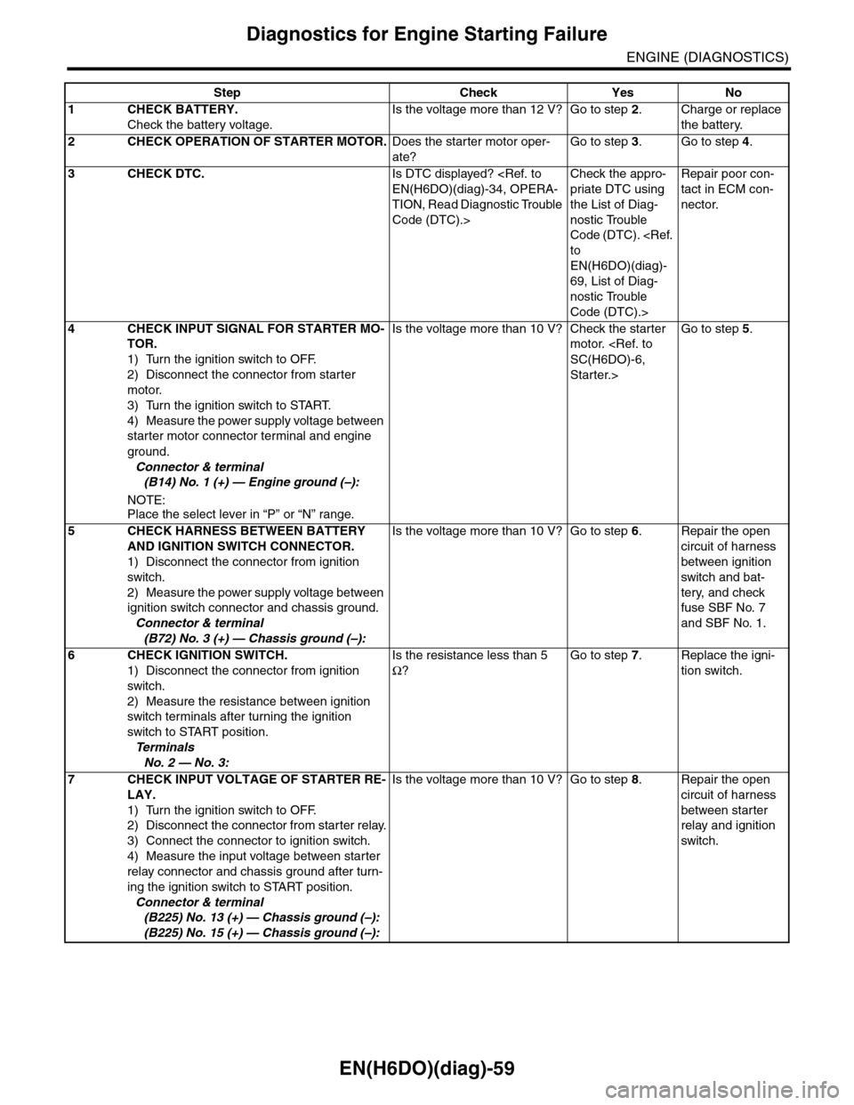
Step Check Yes No
1CHECK BATTERY.
Check the battery voltage.
Is the voltage more than 12 V? Go to step 2.Charge or replace
the battery.
2CHECK OPERATION OF STARTER MOTOR.Does the starter motor oper-
ate?
Go to step 3.Go to step 4.
3CHECK DTC.Is DTC displayed?
EN(H6DO)(diag)-34, OPERA-
TION, Read Diagnostic Trouble
Code (DTC).>
Check the appro-
priate DTC using
the List of Diag-
nostic Trouble
Code (DTC).
to
EN(H6DO)(diag)-
69, List of Diag-
nostic Trouble
Code (DTC).>
Repair poor con-
tact in ECM con-
nector.
4CHECK INPUT SIGNAL FOR STARTER MO-
TOR.
1) Turn the ignition switch to OFF.
2) Disconnect the connector from starter
motor.
3) Turn the ignition switch to START.
4) Measure the power supply voltage between
starter motor connector terminal and engine
ground.
Connector & terminal
(B14) No. 1 (+) — Engine ground (–):
NOTE:Place the select lever in “P” or “N” range.
Is the voltage more than 10 V? Check the starter
motor.
SC(H6DO)-6,
Starter.>
Go to step 5.
5CHECK HARNESS BETWEEN BATTERY
AND IGNITION SWITCH CONNECTOR.
1) Disconnect the connector from ignition
switch.
2) Measure the power supply voltage between
ignition switch connector and chassis ground.
Connector & terminal
(B72) No. 3 (+) — Chassis ground (–):
Is the voltage more than 10 V? Go to step 6.Repair the open
circuit of harness
between ignition
switch and bat-
tery, and check
fuse SBF No. 7
and SBF No. 1.
6CHECK IGNITION SWITCH.
1) Disconnect the connector from ignition
switch.
2) Measure the resistance between ignition
switch terminals after turning the ignition
switch to START position.
Te r m i n a l s
No. 2 — No. 3:
Is the resistance less than 5
Ω?
Go to step 7.Replace the igni-
tion switch.
7CHECK INPUT VOLTAGE OF STARTER RE-
LAY.
1) Turn the ignition switch to OFF.
2) Disconnect the connector from starter relay.
3) Connect the connector to ignition switch.
4) Measure the input voltage between starter
relay connector and chassis ground after turn-
ing the ignition switch to START position.
Connector & terminal
(B225) No. 13 (+) — Chassis ground (–):
(B225) No. 15 (+) — Chassis ground (–):
Is the voltage more than 10 V? Go to step 8.Repair the open
circuit of harness
between starter
relay and ignition
switch.
Page 1221 of 2453
EN(H6DO)(diag)-60
Diagnostics for Engine Starting Failure
ENGINE (DIAGNOSTICS)
8CHECK STARTER RELAY.
1) Connect the battery to starter relay termi-
nals No. 15 and No. 16.
2) Measure the resistance between starter
relay terminals.
Te r m i n a l s
No. 13 — No. 14:
Is the resistance less than 1
Ω?
Go to step 9.Replace the
starter relay.
9CHECK INPUT VOLTAGE FROM ECM.
1) Turn the ignition switch to OFF.
2) Connect the connector to starter relay.
3) Disconnect the connectors from ECM.
4) Measure the voltage between ECM and
chassis ground.
Connector & terminal
(B136) No. 32 (+) — Chassis ground (–):
(B136) No. 20 (+) — Chassis ground (–):
Is the voltage more than 10 V? Replace the ECM.
FU(H6DO)-32,
Engine Control
Module (ECM).>
Repair the open or
ground short cir-
cuit of harness
between ECM and
starter relay.
Step Check Yes No
Page 1235 of 2453

EN(H6DO)(diag)-74
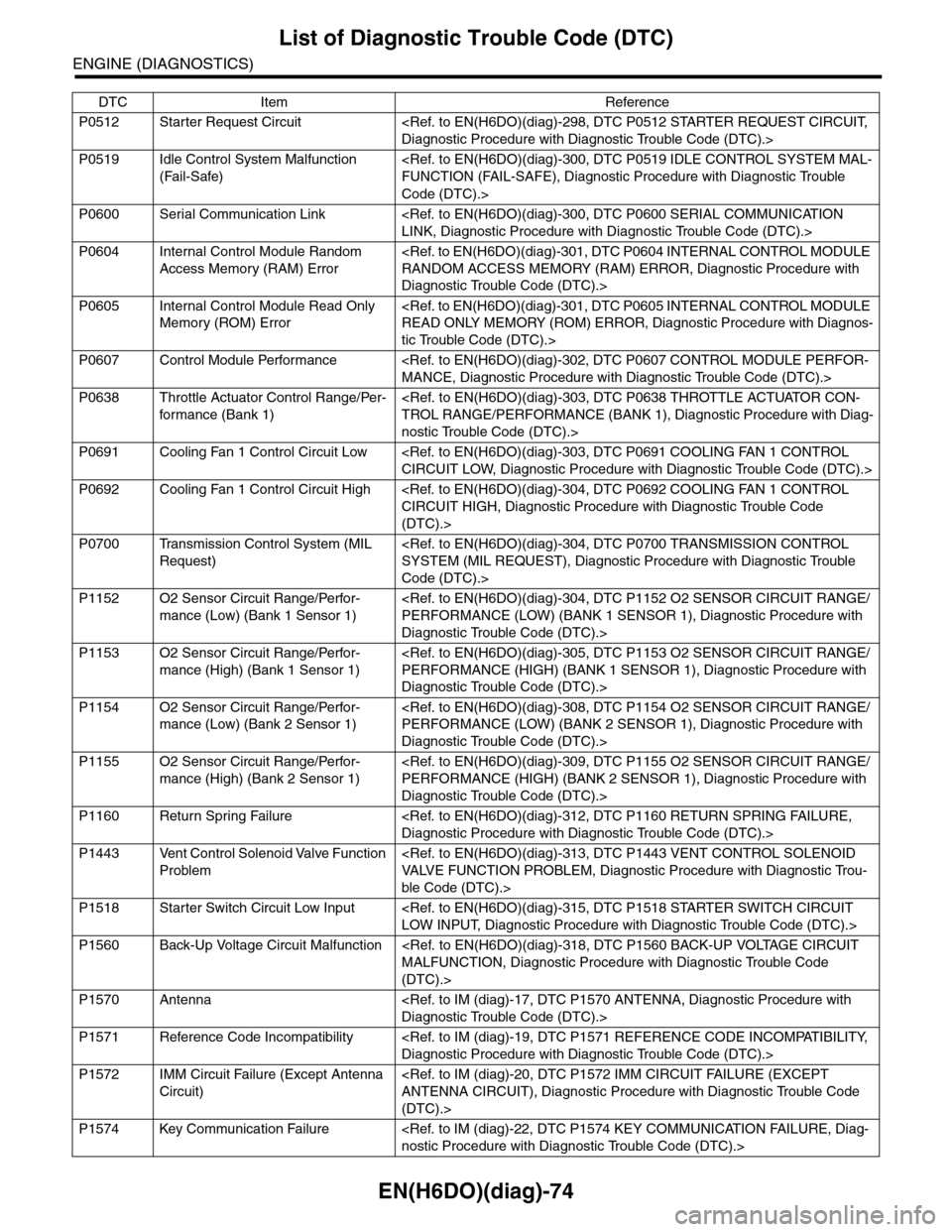
List of Diagnostic Trouble Code (DTC)
ENGINE (DIAGNOSTICS)
P0512 Starter Request Circuit
Diagnostic Procedure with Diagnostic Trouble Code (DTC).>
P0519 Idle Control System Malfunction
(Fail-Safe)
FUNCTION (FAIL-SAFE), Diagnostic Procedure with Diagnostic Trouble
Code (DTC).>
P0600 Serial Communication Link
LINK, Diagnostic Procedure with Diagnostic Trouble Code (DTC).>
P0604 Internal Control Module Random
Access Memory (RAM) Error
RANDOM ACCESS MEMORY (RAM) ERROR, Diagnostic Procedure with
Diagnostic Trouble Code (DTC).>
P0605 Internal Control Module Read Only
Memory (ROM) Error
READ ONLY MEMORY (ROM) ERROR, Diagnostic Procedure with Diagnos-
tic Trouble Code (DTC).>
P0607 Control Module Performance
MANCE, Diagnostic Procedure with Diagnostic Trouble Code (DTC).>
P0638 Throttle Actuator Control Range/Per-
for mance (Bank 1)
TROL RANGE/PERFORMANCE (BANK 1), Diagnostic Procedure with Diag-
nostic Trouble Code (DTC).>
P0691 Cooling Fan 1 Control Circuit Low
CIRCUIT LOW, Diagnostic Procedure with Diagnostic Trouble Code (DTC).>
P0692 Cooling Fan 1 Control Circuit High
CIRCUIT HIGH, Diagnostic Procedure with Diagnostic Trouble Code
(DTC).>
P0700 Transmission Control System (MIL
Request)
SYSTEM (MIL REQUEST), Diagnostic Procedure with Diagnostic Trouble
Code (DTC).>
P1152 O2 Sensor Circuit Range/Perfor-
mance (Low) (Bank 1 Sensor 1)
PERFORMANCE (LOW) (BANK 1 SENSOR 1), Diagnostic Procedure with
Diagnostic Trouble Code (DTC).>
P1153 O2 Sensor Circuit Range/Perfor-
mance (High) (Bank 1 Sensor 1)
PERFORMANCE (HIGH) (BANK 1 SENSOR 1), Diagnostic Procedure with
Diagnostic Trouble Code (DTC).>
P1154 O2 Sensor Circuit Range/Perfor-
mance (Low) (Bank 2 Sensor 1)
PERFORMANCE (LOW) (BANK 2 SENSOR 1), Diagnostic Procedure with
Diagnostic Trouble Code (DTC).>
P1155 O2 Sensor Circuit Range/Perfor-
mance (High) (Bank 2 Sensor 1)
PERFORMANCE (HIGH) (BANK 2 SENSOR 1), Diagnostic Procedure with
Diagnostic Trouble Code (DTC).>
P1160 Return Spring Failure
Diagnostic Procedure with Diagnostic Trouble Code (DTC).>
P1443 Vent Control Solenoid Valve Function
Problem
VA LV E F U N C T I O N P R O B L E M , D i a g n o s t i c P r o c e d u r e w i t h D i a g n o s t i c Tr o u -
ble Code (DTC).>
P1518 Starter Switch Circuit Low Input
LOW INPUT, Diagnostic Procedure with Diagnostic Trouble Code (DTC).>
P1560 Back-Up Voltage Circuit Malfunction
MALFUNCTION, Diagnostic Procedure with Diagnostic Trouble Code
(DTC).>
P1570 Antenna
Diagnostic Trouble Code (DTC).>
P1571 Reference Code Incompatibility
Diagnostic Procedure with Diagnostic Trouble Code (DTC).>
P1572 IMM Circuit Failure (Except Antenna
Circuit)
ANTENNA CIRCUIT), Diagnostic Procedure with Diagnostic Trouble Code
(DTC).>
P1574 Key Communication Failure
nostic Procedure with Diagnostic Trouble Code (DTC).>
DTC Item Reference
Page 1459 of 2453
EN(H6DO)(diag)-298
Diagnostic Procedure with Diagnostic Trouble Code (DTC)
ENGINE (DIAGNOSTICS)
CU:DTC P0512 STARTER REQUEST CIRCUIT
DTC DETECTING CONDITION:
•Immediately at fault recognition
•GENERAL DESCRIPTION
nostic Trouble Code (DTC) Detecting Criteria.>
TROUBLE SYMPTOM:
Failure of engine to start
CAUTION:
After repair or replacement of faulty parts, perform Clear Memory Mode
OPERATION, Clear Memory Mode.> and Inspection Mode
Inspection Mode.>.
Page 1460 of 2453
EN(H6DO)(diag)-299
Diagnostic Procedure with Diagnostic Trouble Code (DTC)
ENGINE (DIAGNOSTICS)
WIRING DIAGRAM:
EN-03735
3220
NO.21
B225
MAIN SBFSBF-6
E
1513
1614
ECM
B136
B72
B14
M
23
B72B225
101112
131415 16
17181920
21222324
25262728
293031 32
333435 36 39 40
3738
129
34
56
78
134562
BATTERY
IGNITIONSWITCH
STARTERRELAYSTARTER MOTOR
B136
16101112131415252430
9871718192028212223293231
123456
2726333435
Page 1461 of 2453

EN(H6DO)(diag)-300
Diagnostic Procedure with Diagnostic Trouble Code (DTC)
ENGINE (DIAGNOSTICS)
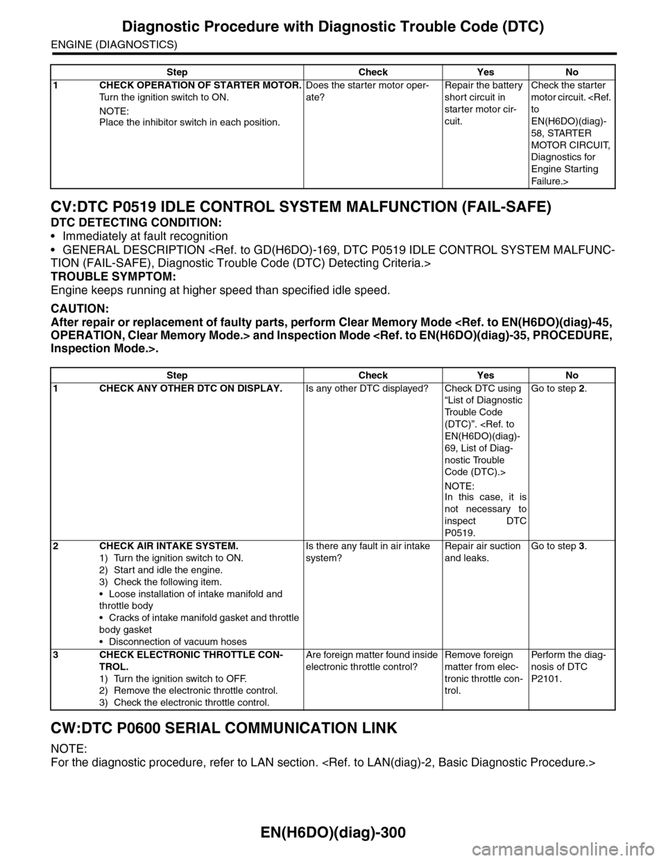
CV:DTC P0519 IDLE CONTROL SYSTEM MALFUNCTION (FAIL-SAFE)
DTC DETECTING CONDITION:
•Immediately at fault recognition
•GENERAL DESCRIPTION
TION (FAIL-SAFE), Diagnostic Trouble Code (DTC) Detecting Criteria.>
TROUBLE SYMPTOM:
Engine keeps running at higher speed than specified idle speed.
CAUTION:
After repair or replacement of faulty parts, perform Clear Memory Mode
OPERATION, Clear Memory Mode.> and Inspection Mode
Inspection Mode.>.
CW:DTC P0600 SERIAL COMMUNICATION LINK
NOTE:
For the diagnostic procedure, refer to LAN section.
Step Check Yes No
1CHECK OPERATION OF STARTER MOTOR.
Tu r n t h e i g n i t i o n s w i t c h t o O N .
NOTE:
Place the inhibitor switch in each position.
Does the starter motor oper-
ate?
Repair the battery
short circuit in
starter motor cir-
cuit.
Check the starter
motor circuit.
to
EN(H6DO)(diag)-
58, STARTER
MOTOR CIRCUIT,
Diagnostics for
Engine Starting
Fai lu r e.>
Step Check Yes No
1CHECK ANY OTHER DTC ON DISPLAY.Is any other DTC displayed? Check DTC using
“List of Diagnostic
Tr o u b l e C o d e
(DTC)”.
EN(H6DO)(diag)-
69, List of Diag-
nostic Trouble
Code (DTC).>
NOTE:In this case, it is
not necessary to
inspect DTC
P0519.
Go to step 2.
2CHECK AIR INTAKE SYSTEM.
1) Turn the ignition switch to ON.
2) Start and idle the engine.
3) Check the following item.
•Loose installation of intake manifold and
throttle body
•Cracks of intake manifold gasket and throttle
body gasket
•Disconnection of vacuum hoses
Is there any fault in air intake
system?
Repair air suction
and leaks.
Go to step 3.
3CHECK ELECTRONIC THROTTLE CON-
TROL.
1) Turn the ignition switch to OFF.
2) Remove the electronic throttle control.
3) Check the electronic throttle control.
Are foreign matter found inside
electronic throttle control?
Remove foreign
matter from elec-
tronic throttle con-
trol.
Per fo r m th e di ag -
nosis of DTC
P2101.