2009 NISSAN TIIDA wheel
[x] Cancel search: wheelPage 2667 of 4331
![NISSAN TIIDA 2009 Service Repair Manual DTC P0441 EVAP CONTROL SYSTEM
EC-1311
< SERVICE INFOMATION >
[MR TYPE 2] C
D E
F
G H
I
J
K L
M A EC
NP
O
1. Start engine and warm it up to normal operating temperature.
2. Turn ignition switch OFF and](/manual-img/5/57398/w960_57398-2666.png "NISSAN TIIDA 2009 Service Repair Manual DTC P0441 EVAP CONTROL SYSTEM
EC-1311
< SERVICE INFOMATION >
[MR TYPE 2] C
D E
F
G H
I
J
K L
M A EC
NP
O
1. Start engine and warm it up to normal operating temperature.
2. Turn ignition switch OFF and")
DTC P0441 EVAP CONTROL SYSTEM
EC-1311
< SERVICE INFOMATION >
[MR TYPE 2] C
D E
F
G H
I
J
K L
M A EC
NP
O
1. Start engine and warm it up to normal operating temperature.
2. Turn ignition switch OFF and wait at least 10 seconds.
3. Start engine and let it idle for at least 70 seconds.
4. Select “PURG FLOW P0441” of “EVAPORATIVE SYSTEM” in “DTC CONFIRMATION” mode with CON-
SULT-III.
5. Touch “START”.
If “COMPLETED” is displayed, go to step 7.
6. When the following conditions are met, “TESTING ” will be displayed on the CONSULT-III screen. Maintain
the conditions continuously until “TES TING” changes to “COMPLETED”. (It will take at least 35 seconds.)
If TESTING is not changed for a long time, retry from step 2.
7. Make sure that “OK” is displayed after touching “S ELF-DIAG RESULTS”. If “NG” is displayed, refer to EC-1311, " Diagnosis Procedure " .
Overall Function Check INFOID:0000000004500173
Use this procedure to check the overall monitoring func tion of the EVAP control system purge flow monitoring.
During this check, a 1st trip DTC might not be confirmed.
WITH GST
1. Lift up drive wheels.
2. Start engine and warm it up to normal operating temperature.
3. Turn ignition switch OFF and wait at least 10 seconds.
4. Start engine and wait at least 70 seconds.
5. Set voltmeter probes to ECM te rminals 42 (EVAP control system
pressure sensor signal) and ground.
6. Check EVAP control system pressure sensor value at idle speed and note it.
7. Establish and maintain the following conditions for at least 1 minute.
8. Verify that EVAP contro l system pressure sensor value stays 0. 1V less than the value at idle speed (mea-
sured at step 6) for at least 1 second.
9. If NG, go to EC-1311, " Diagnosis Procedure " .
Diagnosis Procedure INFOID:00000000045001741.
CHECK EVAP CANISTER
1. Turn ignition switch OFF.
2. Check EVAP canister for cracks.
OK or NG OK (With CONSULT-III)>>GO TO 2.
OK (Without CONSULT-III)>>GO TO 3.
NG >> Replace EVAP canister. 2.
CHECK PURGE FLOW
Shift lever Suitable position
VHCL SPEED SE 32 - 120 km/h (20 - 75 MPH)
ENG SPEED 500 - 3,800 rpm
B/FUEL SCHDL 1.0 - 10.0 msec
COOLAN TEMP/S More than 0 °C Air conditioner switch ON
Headlamp switch ON
Rear window defogger switch ON
Engine speed Approx. 3,000 rpm
Shift lever Any position other than P, N or R PBIB3313E
Page 2743 of 4331
EC
NP
O
DTC P0500 VSS
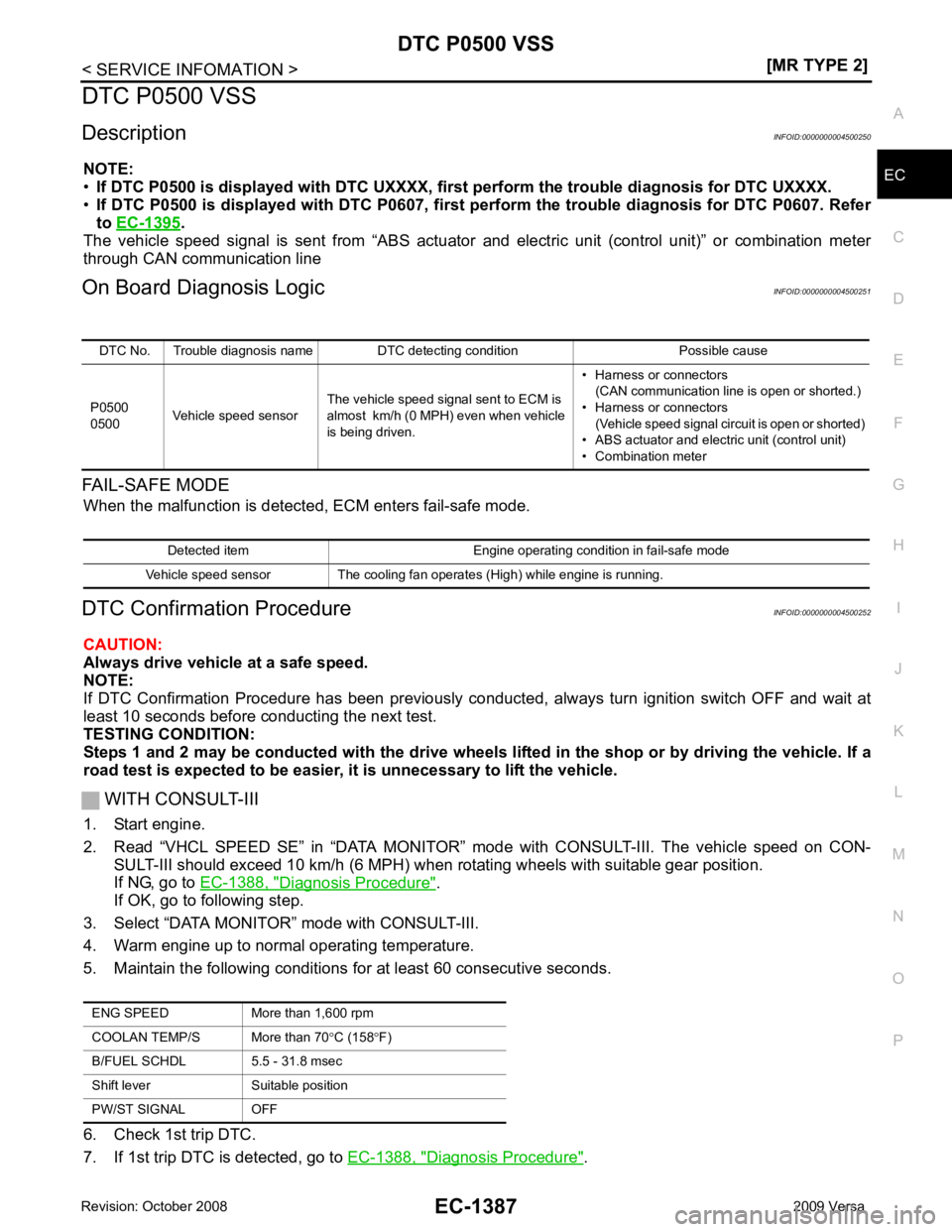
Description INFOID:0000000004500250
NOTE:
• If DTC P0500 is displayed with DTC UXXXX, first perform the tr ouble diagnosis for DTC UXXXX.
• If DTC P0500 is displayed with DT C P0607, first perform the trouble diagnosis for DTC P0607. Refer
to EC-1395 .
The vehicle speed signal is sent from “ABS actuator and electric unit (control unit)” or combination meter
through CAN communication line
On Board Diagnosis Logic INFOID:0000000004500251
FAIL-SAFE MODE When the malfunction is detect ed, ECM enters fail-safe mode.
DTC Confirmation Procedure INFOID:0000000004500252
CAUTION:
Always drive vehicle at a safe speed.
NOTE:
If DTC Confirmation Procedure has been previously conduc ted, always turn ignition switch OFF and wait at
least 10 seconds before conducting the next test.
TESTING CONDITION:
Steps 1 and 2 may be conducted with the drive wheels li fted in the shop or by driving the vehicle. If a
road test is expected to be easier, it is unnecessary to lift the vehicle.
WITH CONSULT-III
1. Start engine.
2. Read “VHCL SPEED SE” in “DATA MONITOR” m ode with CONSULT-III. The vehicle speed on CON-
SULT-III should exceed 10 km/h (6 MPH) when rotating wheels with suitable gear position.
If NG, go to EC-1388, " Diagnosis Procedure " .
If OK, go to following step.
3. Select “DATA MONITOR” mode with CONSULT-III.
4. Warm engine up to normal operating temperature.
5. Maintain the following conditions for at least 60 consecutive seconds.
6. Check 1st trip DTC.
7. If 1st trip DTC is detected, go to EC-1388, " Diagnosis Procedure " .
DTC No. Trouble diagnosis name DTC detecting condition Possible cause
P0500
0500 Vehicle speed sensor The vehicle speed signal sent to ECM is
almost km/h (0 MPH) even when vehicle
is being driven. • Harness or connectors
(CAN communication line is open or shorted.)
• Harness or connectors (Vehicle speed signal circuit is open or shorted)
• ABS actuator and electric unit (control unit)
• Combination meter Detected item Engine operating condition in fail-safe mode
Vehicle speed sensor The cooling fan operates (High) while engine is running. ENG SPEED More than 1,600 rpm
COOLAN TEMP/S More than 70 °C (158 °F)
B/FUEL SCHDL 5.5 - 31.8 msec
Shift lever Suitable position
PW/ST SIGNAL OFF
Page 2794 of 4331

for ASCD functions.
On Board Diagn osis Logic INFOID:0000000004500316
NOTE:
• If DTC P1574 is displayed with DTC UXXXX, first perform the tr ouble diagnosis for DTC UXXXX.
• If DTC P1574 is displayed with DTC P0500, first pe rform the trouble diagnosis for DTC P0500. Refer
to EC-1387 .
This self-diagnosis has the one trip detection logic.
The MIL will not light up for this diagnosis.
DTC Confirmation Procedure INFOID:0000000004500317
CAUTION:
Always drive vehicle at a safe speed.
NOTE:
If DTC Confirmation Procedure has been previously conduc ted, always turn ignition switch OFF and wait at
least 10 seconds before conducting the next test.
TESTING CONDITION:
Step 3 may be conducted with the drive wheels lifted in the shop or by driving the vehicle. If a road test
is expected to be easier, it is unnecessary to lift the vehicle.
1. Start engine.
2. Drive the vehicle at more than 40 km/h (25MPH).
3. Check DTC.
4. If DTC is detected, go to EC-1438, " Diagnosis Procedure " .
Diagnosis Procedure INFOID:0000000004500318 (A/T) or
CVT-209 (CVT).
OK or NG OK >> GO TO 2.
NG >> Perform trouble shooting relevant to DTC indicated. .
OK or NG OK >> GO TO 3.DTC No.
Trouble diagnosis
name DTC detecting condition Possible cause
P1574
1574 ASCD vehicle speed
sensor ECM detects a difference between two vehicle
speed signals is out of the specified range. • Harness or connectors
(CAN communication line is open or shorted.)
• Harness or connectors (Combination meter circuit is open or shorted.)
• TCM
• ABS actuator and electric unit (control unit)
• Combination meter
• ECM
Page 2892 of 4331

EI
N
O P
CONTENTS
EXTERIOR & INTERIOR
PRECAUTION ....... ........................................3
PRECAUTIONS .............................................. .....3
Precaution for Supplemental Restraint System
(SRS) "AIR BAG" and "SEAT BELT PRE-TEN-
SIONER" ............................................................. ......
3
Precaution Necessary fo r Steering Wheel Rota-
tion After Battery Disconnect ............................... ......
3
Precaution ........................................................... ......4
PREPARATION .... ........................................5
PREPARATION .............................................. .....5
Special Service Tool ........................................... ......5
Commercial Service Tool .................................... ......5
SYMPTOM DIAGNOSIS ..... ..........................6
SQUEAK AND RATTLE TROUBLE DIAGNO-
SIS .................................................................. .....6
Work Flow ........................................................... ......6
Generic Squeak and Rattle Troubleshooting ...... ......8
Diagnostic Worksheet ......................................... ....10
CLIP AND FASTENER ................................... ....12
Description .......................................................... ....12
ON-VEHICLE REPAIR .... .............................15
FRONT BUMPER ........................................... ....15
Removal and Installation .........................................15
REAR BUMPER ............................................. ....17
Component .......................................................... ....17
Removal and Installation - Hatchback .....................18
Removal and Installation - Sedan ....................... ....19
FRONT GRILLE ............................................. ....21
Removal and Installation .........................................21
COWL TOP ..................................................... ....22
Removal and Installation .........................................22 FENDER PROTECTOR ....................................
24
Component .......................................................... ....24
Removal and Installation ..................................... ....24
ROOF SIDE MOLDING ..................................... 25
Component .......................................................... ....25
Removal and Installation ..................................... ....25
DOOR OUTSIDE MOLDING ............................. 27
Component .......................................................... ....27
Removal and Installation ..................................... ....28
CENTER MUD GUARD ..................................... 30
Removal and Installation ..................................... ....30
TRUNK LID FINISHER ...................................... 31
Removal and Installation ..................................... ....31
REAR AIR SPOILER ......................................... 32
Removal and Installation ..................................... ....32
DOOR FINISHER .............................................. 34
Removal and Installation ..................................... ....34
BACK DOOR TRIM ........................................... 38
Removal and Installation ..................................... ....38
BODY SIDE TRIM ............................................. 39
Component .......................................................... ....39
Removal and Installation ..................................... ....40
REAR PARCEL SHELF FINISHER .................. 44
Removal and Installation ..................................... ....44
FLOOR TRIM .................................................... 45
Removal and Installation ..................................... ....45
HEADLINING .................................................... 47
Component .......................................................... ....47
Removal and Installation - Hatchback ................. ....49
Removal and Installation - Sedan ........................ ....51
LUGGAGE FLOOR TRIM ................................. 53
Page 2894 of 4331

EI
N
O P
PRECAUTION
PRECAUTIONS
Precaution for Supplemental Restraint System (SRS) "AIR BAG" and "SEAT BELT
PRE-TENSIONER" INFOID:0000000004783758
The Supplemental Restraint System such as “A IR BAG” and “SEAT BELT PRE-TENSIONER”, used along
with a front seat belt, helps to reduce the risk or severi ty of injury to the driver and front passenger for certain
types of collision. This system includes seat belt switch inputs and dual stage front air bag modules. The SRS
system uses the seat belt switches to determine the front air bag deployment, and may only deploy one front
air bag, depending on the severity of a collision and w hether the front occupants are belted or unbelted.
Information necessary to service the system safely is included in the SRS and SB section of this Service Man-
ual.
WARNING:
• To avoid rendering the SRS inoper ative, which could increase the risk of personal injury or death in
the event of a collision which would result in air bag inflation, all maintenance must be performed by
an authorized NISSAN/INFINITI dealer.
• Improper maintenance, including in correct removal and installation of the SRS can lead to personal
injury caused by unintentional act ivation of the system. For removal of Spiral Cable and Air Bag
Module, see the SRS section.
• Do not use electrical test equipm ent on any circuit related to the SRS unless instructed to in this
Service Manual. SRS wiring harnesses can be identi fied by yellow and/or orange harnesses or har-
ness connectors.
• When working near the Airbag Diagnosis Sensor Un it or other Airbag System sensors with the Igni-
tion ON or engine running, DO NOT use air or el ectric power tools or strike near the sensor(s) with a
hammer. Heavy vibration could activate the sensor( s) and deploy the air bag(s), possibly causing
serious injury.
• When using air or electric power tools or hammers , always switch the Ignition OFF, disconnect the
battery, and wait at least 3 minutes before performing any service.
Precaution Necessary for Steering Wh eel Rotation After Battery Disconnect
INFOID:0000000004685432
NOTE:
• This Procedure is applied only to models with Inte lligent Key system and NATS (NISSAN ANTI-THEFT SYS-
TEM).
• Remove and install all control units after disconnecti ng both battery cables with the ignition knob in the
″ LOCK ″ position.
• Always use CONSULT-III to perform self-diagnosis as a part of each function inspection after finishing work.
If DTC is detected, perform trouble diagnosis according to self-diagnostic results.
For models equipped with the Intelligent Key system and NATS , an electrically controlled steering lock mech-
anism is adopted on the key cylinder.
For this reason, if the battery is disconnected or if the battery is discharged, the steering wheel will lock and
steering wheel rotation will become impossible.
If steering wheel rotation is required when battery pow er is interrupted, follow the procedure below before
starting the repair operation.
OPERATION PROCEDURE 1. Connect both battery cables. NOTE:
Supply power using jumper cables if battery is discharged.
2. Use the Intelligent Key or mechanical key to turn the ignition switch to the ″ACC ″ position. At this time, the
steering lock will be released.
3. Disconnect both battery cables. The steering lock will remain released and the steering wheel can be
rotated.
4. Perform the necessary repair operation.
5. When the repair work is completed, return the ignition switch to the ″LOCK ″ position before connecting
the battery cables. (At this time, the steering lock mechanism will engage.)
6. Perform a self-diagnosis check of al l control units using CONSULT-III.
Page 2948 of 4331

EM
N
O P
CONTENTS
ENGINE MECHANICAL
HR16DE
PRECAUTION ....... ........................................
4
PRECAUTIONS .............................................. .....4
Precaution for Supplemental Restraint System
(SRS) "AIR BAG" and "SEAT BELT PRE-TEN-
SIONER" ............................................................. ......
4
Precaution Necessary fo r Steering Wheel Rota-
tion After Battery Disconnect ............................... ......
4
Precaution for Procedure without Cowl Top Cover ......5
Precaution for Drain Cool ant .....................................5
Precaution for Disconnecting Fuel Piping ........... ......5
Precaution for Removal and Disassembly ................5
Precaution for Inspection, Repair and Replace-
ment .................................................................... ......
5
Precaution for Assembly and Installation ..................5
Parts Requiring Angular Tightening ..........................6
Precaution for Liquid Gasket ............................... ......6
PREPARATION .... ........................................8
PREPARATION .............................................. .....8
Special Service Tools .......................................... ......8
Commercial Service Tools .................................. ......9
SYMPTOM DIAGNOSIS ..... .........................12
NOISE, VIBRATION AND HARSHNESS
(NVH) TROUBLESHOOTING ........................ ....
12
NVH Troubleshooting - Engine Noise ................. ....12
Use the Chart Below to Help You Find the Cause
of the Symptom ................................................... ....
13
ON-VEHICLE MAINTENA NCE ....................14
DRIVE BELTS ................................................ ....14
Checking ............................................................. ....14
Tension Adjustment ............................................ ....14
Removal and Installation .........................................15
AIR CLEANER FILTER .................................. ....17 Removal and Installation .....................................
....17
SPARK PLUG ................................................... 18
Exploded View ..................................................... ....18
Removal and Installation ..................................... ....18
CAMSHAFT VALVE CLEARANCE .................. 20
Inspection and Adjustment .................................. ....20
COMPRESSION PRESSURE ........................... 23
Inspection ............................................................ ....23
ON-VEHICLE REPAIR ..... ............................24
DRIVE BELT IDLER PULLEY .......................... 24
Exploded View ..................................................... ....24
Removal and Installation ..................................... ....24
AIR CLEANER AND AIR DUCT ....................... 26
Exploded View ..................................................... ....26
Removal and Installation ..................................... ....26
Inspection ............................................................ ....27
INTAKE MANIFOLD ......................................... 28
Exploded View ..................................................... ....28
Removal and Installation ..................................... ....28
EXHAUST MANIFOLD ...................................... 31
Exploded View ..................................................... ....31
Removal and Installation ..................................... ....31
FUEL INJECTOR AND FUEL TUBE ................ 34
Exploded View ..................................................... ....34
Removal and Installation ..................................... ....34
Inspection ............................................................ ....38
OIL PAN (LOWER) ........................................... 39
Exploded View ..................................................... ....39
Removal and Installation ..................................... ....39
Inspection ............................................................ ....41
OIL PAN (UPPER) AND OIL STRAINER ......... 42
Component .......................................................... ....42
Page 2956 of 4331
EM
NP
O
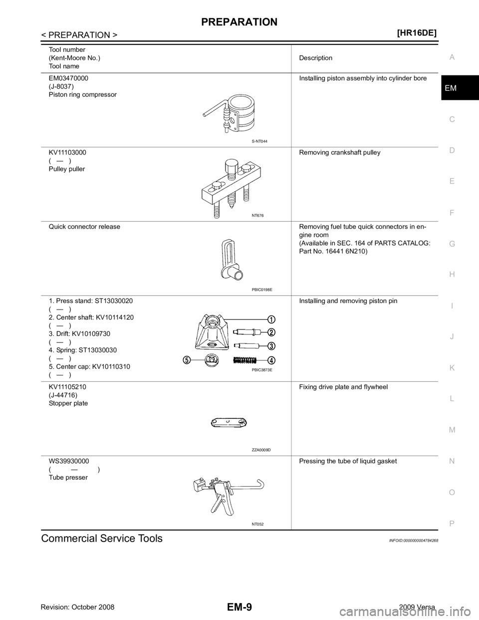
Commercial Service Tools INFOID:0000000004784268
EM03470000
(J-8037)
Piston ring compressor Installing piston assembly into cylinder bore
KV11103000
( — )
Pulley puller Removing crankshaft pulley
Quick connector release Removing fuel tube quick connectors in en- gine room
(Available in SEC. 164 of PARTS CATALOG:
Part No. 16441 6N210)
1. Press stand: ST13030020
( — )
2. Center shaft: KV10114120
( — )
3. Drift: KV10109730
( — )
4. Spring: ST13030030
( — )
5. Center cap: KV10110310
( — ) Installing and removing piston pin
KV11105210
(J-44716)
Stopper plate Fixing drive plate and flywheel
WS39930000
( — )
Tube presser Pressing the tube of liquid gasket
Tool number
(Kent-Moore No.)
Tool name Description PBIC0198E
PBIC3873E
ZZA0009D
NT052
Page 2996 of 4331
EM
NP
O
TIMING CHAIN
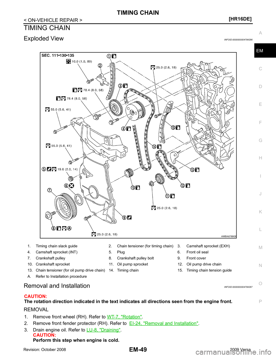
Exploded View INFOID:0000000004784296
Removal and Installation INFOID:0000000004784297
CAUTION:
The rotation direction indicated in the text indicates all directions seen from the engine front.
REMOVAL 1. Remove front wheel (RH). Refer to WT-7, " Rotation " .
2. Remove front fender protector (RH). Refer to EI-24, " Removal and Installation " .
3. Drain engine oil. Refer to LU-8, " Draining " .
CAUTION:
Perform this step when engine is cold.
1. Timing chain slack guide 2. Chain tensioner (for timing chain) 3. Camshaft sprocket (EXH)
4. Camshaft sprocket (INT) 5. Plug 6. Front oil seal
7. Crankshaft pulley 8. Crankshaft pulley bolt 9. Front cover
10. Crankshaft sprocket 11. Oil pump sprocket 12. Oil pump drive chain
13. Chain tensioner (for oil pump drive chain) 14. Timing chain 15. Timing chain tension guide
A. Refer to Installation procedure