2009 NISSAN TIIDA Back door diagram
[x] Cancel search: Back door diagramPage 462 of 4331

BL
N
O P
CONTENTS
BODY, LOCK & SECURITY SYSTEM
SERVICE INFORMATION .. ..........................4
PRECAUTIONS .............................................. .....4
Precaution for Supplemental Restraint System
(SRS) "AIR BAG" and "SEAT BELT PRE-TEN-
SIONER" ............................................................. ......
4
Precaution Necessary fo r Steering Wheel Rota-
tion After Battery Disconnect ............................... ......
4
Precaution for Procedure without Cowl Top Cover ......5
Precaution for Work ............................................ ......5
PREPARATION .............................................. .....6
Special Service Tool ........................................... ......6
Commercial Service Tool .................................... ......6
SQUEAK AND RATTLE TROUBLE DIAG-
NOSES ........................ ........................................7
Work Flow ........................................................... ......7
Generic Squeak and Rattle Troubleshooting ...... ......9
Diagnostic Worksheet ......................................... ....11
HOOD ............................................................. ....13
Fitting Adjustment ............................................... ....13
Removal and Installation .........................................14
Removal and Installation of Hood Lock Control .. ....15
Hood Lock Control Inspec tion .................................17
RADIATOR CORE SUPPORT ....................... ....19
Removal and Installation .........................................19
FRONT FENDER ............................................ ....21
Removal and Installation .........................................21
POWER DOOR LOCK SYSTEM .................... ....22
Component Parts and Harness Connector Loca-
tion ...................................................................... ....
22
System Description ............................................. ....23
CAN Communication System Description ........... ....25
Schematic ........................................................... ....26
Wiring Diagram - D/LOCK - ................................. ....27
Schematic ........................................................... ....31
Wiring Diagram - D/LOCK - ................................. ....32 Terminal and Reference
Value for BCM ..................37
Work Flow ............................................................ ....41
CONSULT-III Function (B CM) .................................41
Trouble Diagnosis Symptom Chart ...................... ....43
BCM Power Supply and Ground Circuit Inspection ....43
Door Switch Check (Hatchback) .......................... ....44
Door Switch Check (Sedan) ................................ ....47
Key Switch (Insert) Check ................................... ....48
Door Lock and Unlock Switch Check .................. ....49
Front Door Lock Assembly LH (Actuator) Check .....52
Door Lock Actuator Check (Front RH and Rear
LH/RH) ................................................................. ....
53
Front Door Key Cylinder S witch LH Check ..............54
Passenger Select Unlock Relay Circuit Inspection
(With Intelligent Key) ........................................... ....
55
REMOTE KEYLESS ENTRY SYSTEM ............. 58
Component Parts and Harness Connector Loca-
tion ....................................................................... ....
58
System Description .............................................. ....58
CAN Communication System Description ........... ....60
Schematic ............................................................ ....61
Wiring Diagram - KEYLES - ................................ ....62
Terminal and Reference Value for BCM ..................65
How to Perform Trouble Diagnosis ...................... ....69
Preliminary Check ............................................... ....69
CONSULT-III Function (B CM) .................................69
Work Flow ............................................................ ....71
Trouble Diagnosis Symptom Chart ...................... ....71
Keyfob Battery and Function Check .................... ....72
ACC Switch Check .............................................. ....74
Door Switch Check (Hatchback) .......................... ....74
Door Switch Check (Sedan) ................................ ....76
Key Switch (Insert) Check ................................... ....78
Hazard Function Check ....................................... ....78
Horn Function Check ........................................... ....79
Interior Lamp and Ignition Keyhole Illumination
Function Check .................................................... ....
79
Remote Keyless Entry Rece iver Check ...................80
Keyfob Function (Lock) Check ............................ ....82
Page 634 of 4331
BL
N
O P
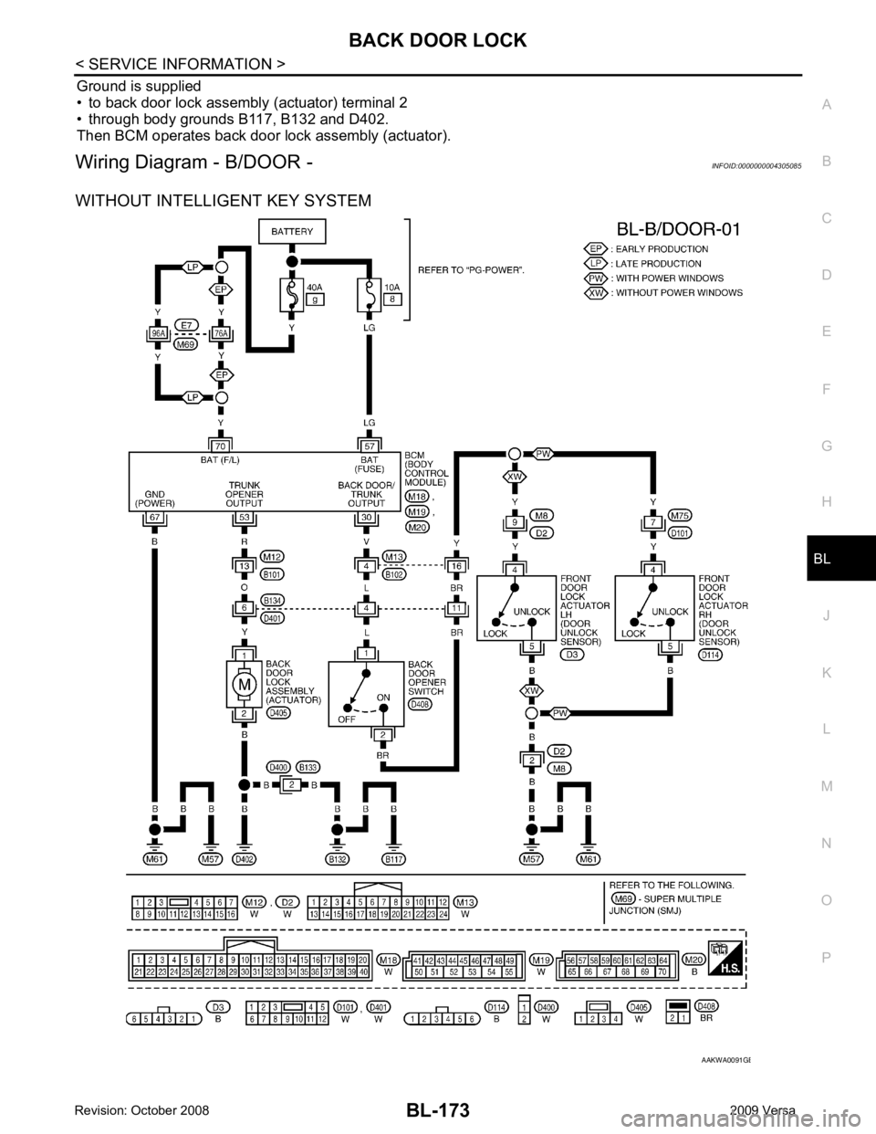
Ground is supplied
• to back door lock assembly (actuator) terminal 2
• through body grounds B117, B132 and D402.
Then BCM operates back door lock assembly (actuator).
Wiring Diagram - B/DOOR - INFOID:0000000004305085
WITHOUT INTELLIGENT KEY SYSTEM B
Page 3271 of 4331
GI-18< SERVICE INFORMATION >
HOW TO USE THIS MANUAL
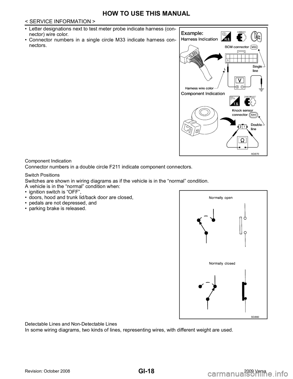
• Letter designations next to test meter probe indicate harness (con- nector) wire color.
• Connector numbers in a single circle M33 indicate harness con-
nectors.
Component Indication
Connector numbers in a double circle F211 indicate component connectors.
Switch Positions
Switches are shown in wiring diagrams as if the vehicle is in the “normal” condition.
A vehicle is in the “normal” condition when:
• ignition switch is “OFF”,
• doors, hood and trunk lid/back door are closed,
• pedals are not depressed, and
• parking brake is released.
Detectable Lines and Non-Detectable Lines
In some wiring diagrams, two kinds of lines, r epresenting wires, with different weight are used. AGI070
SGI860
Page 4040 of 4331

PG
N
O P
Wiring Diagram Codes (Cell Codes)
INFOID:0000000004306667
Use the chart below to find out what each wiring diagram code stands for.
Refer to the wiring diagram code in the alphabetical index to find the location (page number) of each wiring
diagram. D4 D405 W/4 : Back door lock assembly C2 D413 B/1 : Rear window defogger (-)
D4 D406 W/2 : Back door request switch F3 D414 — : Body ground
E2 D407 W/2 : High mounted stop lamp Code Section Wiring Diagram Name
ABS BRC Anti-lock Brake System
A/C,M MTC Manual Air Conditioner
APPS1 EC Accelerator Pe dal Position Sensor
A/F EC Air Fuel Ratio Sensor 1
A/FH EC Air Fuel Ratio Sensor 1 Heater
APPS2 EC Accelerator Pe dal Position Sensor
APPS3 EC Accelerator Pe dal Position Sensor
ASC/BS EC ASCD Brake Switch
ASC/SW EC ASCD Steering Switch
ASCBOF EC ASCD Brake Switch
ASCIND EC ASCD Indicator
AT/IND DI A/T Indicator Lamp
AUDIO AV Audio
BACK/L LT Back-up Lamp
BA/FTS AT A/T Fluid Temperature Sensor and TCM Power Supply
B/DOOR BL Back Door Opener
BRK/SW EC Brake Switch
CAN AT CAN Communication Line
CAN CVT CAN Comm unication Line
CAN EC CAN Communication Line
CAN LAN CAN System
CHARGE SC Charging System
CHIME DI Warning Chime
COOL/F EC Cooling Fan Control
COMBSW LT Combination Switch
CVTIND DI CVT Indicator Lamp
D/LOCK BL Power Door Lock
DEF GW Rear Window Defogger
DTRL LT Headlamp - Wi th Daytime Light System
ECTS EC Engine Coolant Temperature Sensor
ENGSS AT Engine Speed Signal
EPS STC Electronic Controlled Power Steering
ETC1 EC Electric Throttle Control Function
ETC2 EC Throttle Control Motor Relay
ETC3 EC Throttle Control Motor
F/FOG LT Front Fog Lamp
F/PUMP EC Fuel Pump
FTS AT A/T Fluid Temperature Sensor
FTS CVT CVT Fluid Temperature Sensor Circuit
FTTS EC Fuel Tank Temperature Sensor
FUEL EC Fuel Ignition System Function
HEATER MTC Heater System