2009 NISSAN TIIDA transmission
[x] Cancel search: transmissionPage 6 of 4331
AT
N
O P
CONTENTS
AUTOMATIC TRANSAXLE
SERVICE INFORMATION .. ..........................5
INDEX FOR DTC ............................................ .....5
Alphabetical Index ............................................... ......5
DTC No. Index .................................................... ......5
PRECAUTIONS .............................................. .....7
Precaution for Supplemental Restraint System
(SRS) "AIR BAG" and "SEAT BELT PRE-TEN-
SIONER" ............................................................. ......
7
Precaution Necessary fo r Steering Wheel Rota-
tion After Battery Disconnect ............................... ......
7
Precaution for On Board Diagnosis (OBD) System
of A/T and Engine ............................................... ......
8
Precaution ........................................................... ......8
Service Notice or Precaution ............................... ......9
PREPARATION .............................................. ....11
Special Service Tool ........................................... ....11
Commercial Service Tool .................................... ....14
A/T FLUID ....................................................... ....17
Checking A/T Fluid .............................................. ....17
Changing A/T Fluid ............................................. ....17
A/T Fluid Cooler Cleaning ................................... ....18
A/T CONTROL SYSTEM ................................ ....21
Cross-Sectional View ... ...........................................21
Shift Mechanism .................................................. ....22
TCM Function ...................................................... ....30
CAN Communication ........................................... ....31
Input/Output Signal of TCM ................................. ....31
Line Pressure Control .. ...........................................32
Shift Control ........................................................ ....33
Lock-up Control ................................................... ....34
Engine Brake Control (Ove rrun Clutch Control) ......35
Control Valve ....................................................... ....37
Centrifugal Cancel Mechanism ........................... ....37
ON BOARD DIAGNOSTIC (OBD) SYSTEM .. ....39
Introduction ......................................................... ....39
OBD-II Function for A/T System .......................... ....39 One or Two Trip Detection Logic of OBD-II .........
....39
OBD-II Diagnostic Trouble Code (DTC) .............. ....39
Malfunction Indicator Lamp (MIL) ............................41
TROUBLE DIAGNOSIS .................................... 42
DTC Inspection Priority Chart .............................. ....42
Fail-Safe .............................................................. ....42
How to Perform Trouble Diagnosis for Quick and
Accurate Repair ................................................... ....
43
A/T Electrical Parts Location ............................... ....49
Circuit Diagram .................................................... ....50
Inspections Before Trouble Diagnosis ................. ....51
Road Test ............................................................ ....55
Check Before Engine Is Started .......................... ....56
Check at Idle ........................................................ ....56
Cruise Test - Part 1 ............................................. ....58
Cruise Test - Part 2 ............................................. ....61
Cruise Test - Part 3 ............................................. ....62
Vehicle Speed at Which Gear Shifting Occurs .... ....64
Vehicle Speed at Which Lock-up Occurs/Releas-
es ......................................................................... ....
64
Symptom Chart .................................................... ....65
TCM Terminal and Refere nce Value .......................77
CONSULT-III Function (TRANSMISSION) .......... ....79
Diagnosis Procedure withou t CONSULT-III ............83
DTC U1000 CAN COMMUNICATION LINE ..... 88
Description ........................................................... ....88
On Board Diagnosis Logic ................................... ....88
Possible Cause .................................................... ....88
DTC Confirmation Procedure .............................. ....88
Wiring Diagram - AT - CAN ................................. ....89
Diagnosis Procedure ........................................... ....90
DTC P0705 PARK/NEUTRAL POSITION
(PNP) SWITCH .................................................. 91
Description ........................................................... ....91
CONSULT-III Reference Va lue in Data Monitor
Mode .................................................................... ....
91
On Board Diagnosis Logic ................................... ....91
Possible Cause .................................................... ....91
Page 8 of 4331
AT
N
O
P
N
Wiring Diagram - AT -
SSV/B ................................
145
Diagnosis Procedure ........................................... ..146
Component Inspection ........................................ ..147
DTC P1760 OVERRUN CLUTCH SOLENOID
VALVE ............................................................ ..149
Description .......................................................... ..149
CONSULT-III Refe rence Value in Data Monitor
Mode ................................................................... ..
149
On Board Diagnosis Logic .................................. ..149
Possible Cause ................................................... ..149
DTC Confirmation Procedure .............................. ..149
Wiring Diagram - AT - OVRCSV ......................... ..150
Diagnosis Procedure ........................................... ..151
Component Inspection ........................................ ..152
DTC VEHICLE SPEED SENSOR MTR .......... ..154
Description .......................................................... ..154
CONSULT-III Refe rence Value in Data Monitor
Mode ................................................................... ..
154
On Board Diagnosis Logic .................................. ..154
Possible Cause ................................................... ..154
DTC Confirmation Procedure .............................. ..154
Wiring Diagram - AT - VSSMTR ...........................155
Diagnosis Procedure ........................................... ..156
DTC BATT/FLUID TEMP SEN (A/T FLUID
TEMP SENSOR CIRCUIT AND TCM POWER
SOURCE) ....................................................... ..
157
Description .......................................................... ..157
CONSULT-III Refe rence Value in Data Monitor
Mode ................................................................... ..
157
On Board Diagnosis Logic .................................. ..157
Possible Cause ................................................... ..157
DTC Confirmation Procedure .............................. ..157
Wiring Diagram - AT - BA/FTS ............................ ..158
Diagnosis Procedure ........................................... ..159
Component Inspection ........................................ ..161
DTC TURBINE REVOLUTION SENSOR ....... ..163
Description .......................................................... ..163
CONSULT-III Refe rence Value in Data Monitor
Mode ................................................................... ..
163
On Board Diagnosis Logic .................................. ..163
Possible Cause ................................................... ..163
DTC Confirmation Procedure .............................. ..163
Wiring Diagram - AT - PT/SEN ........................... ..164
Diagnosis Procedure ........................................... ..165
CONTROL UNIT (RAM), CONTROL UNIT
(ROM) ............................................................. ..
168
Description .......................................................... ..168
On Board Diagnosis Logic .................................. ..168
Possible Cause ................................................... ..168
DTC Confirmation Procedure .............................. ..168
Diagnosis Procedure ........................................... ..168
MAIN POWER SUPPLY AND GROUND CIR-
CUIT ................................................................ ..169
Wiring Diagram - AT - MAIN ............................... ..169 Diagnosis Procedure ...........................................
..170
PNP, OD SWITCH AND CLOSED THROT-
TLE, WIDE OPEN THROTTLE POSITION
SIGNAL CIRCUI T ............................................ 172
CONSULT-III Reference Va lue in Data Monitor
Mode .................................................................... ..
172
TCM Terminal and Refere nce Value .....................172
Diagnosis Procedure ........................................... ..172
Component Inspection ......................................... ..176
SHIFT POSITION INDICATOR CIRCUIT ........ 177
Description ........................................................... ..177
CONSULT-III Reference Va lue in Data Monitor
Mode .................................................................... ..
177
Diagnosis Procedure ........................................... ..177
TROUBLE DIAGNOSIS FOR SYMPTOMS .... 178
Wiring Diagram - AT - NONDTC ......................... ..178
OD OFF Indicator Lamp Does Not Come On ...... ..181
Engine Cannot Be Started in "P" and "N" Position ..183
In "P" Position, Vehicle Moves Forward or Back-
ward When Pushed ............................................. ..
184
In "N" Position, Vehicle Moves ............................ ..184
Large Shock "N" → "R" Position .......................... ..185
Vehicle Does Not Creep Backward in "R" Position ..186
Vehicle Does Not Creep Forw ard in "D", "2" or "1"
Position ................................................................ ..
187
Vehicle Cannot Be Started from D 1 ..................... ..188
A/T Does Not Shift: D 1→ D 2or Does Not Kick-
down: D 4→ D 2 ..................................................... ..190
A/T Does Not Shift: D 2→ D 3 ................................ ..192
A/T Does Not Shift: D 3→ D 4 ................................ ..193
A/T Does Not Perform Lock-up ........................... ..194
A/T Does Not Hold Lock-up Condition ................. ..195
Lock-up Is Not Released ..................................... ..196
Engine Speed Does Not Return to Idle (Light
Braking D 4→ D 3) ................................................. ..197
A/T Does Not Shift: D 4→ D 3, When OD OFF ...... ..198
A/T Does Not Shift: D 3→ 22, When Selector Lever
"D" → "2" Position ............................................... ..
199
A/T Does Not Shift: 2 2→ 11, When Selector Lever
"2" → "1" Position ................................................ ..
200
Vehicle Does Not Decelerate by Engine Brake ... ..202
TCM Self-Diagnosis Does Not Activate ............... ..205
A/T SHIFT LOCK SYSTEM ............................. 207
Description ........................................................... ..207
Shift Lock System Parts Location ........................ ..207
Wiring Diagram - AT - SHIFT .............................. ..208
Diagnosis Procedure ........................................... ..208
TRANSMISSION CONTROL MODULE .......... 211
Removal and Installation ..................................... ..211
SHIFT CONTROL SYSTEM ............................ 212
Control Device Removal an d Installation ...............212
Control Device Disassembly and Assembly ..........215
Selector Lever Knob Remo val and Installation ......215
Adjustment of A/T Position .................................. ..216
Page 23 of 4331
Checking A/T Fluid " .
A/T Fluid Cooler Cleaning INFOID:0000000004305297
Whenever the A/T is repaired, overhauled, or replaced, the A/T fluid cooler mounted in the radiator must be
inspected and cleaned.
Metal debris and friction material, if present, can becom e trapped in the A/T fluid cooler. This debris can con-
taminate the newly serviced A/T or, in severe cases, can bloc k or restrict the flow of A/T fluid. In either case,
malfunction of the newly serviced A/T may result.
Debris, if present, may build up as A/T fluid enters the c ooler inlet. It will be necessary to back flush the cooler
through the cooler outlet in order to flush out any built up debris.
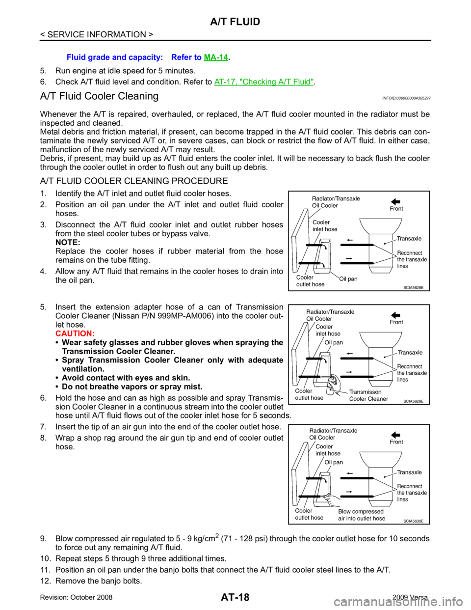
A/T FLUID COOLER CLEANING PROCEDURE
1. Identify the A/T inlet and outlet fluid cooler hoses.
2. Position an oil pan under the A/T inlet and outlet fluid cooler hoses.
3. Disconnect the A/T fluid cooler inlet and outlet rubber hoses from the steel cooler tubes or bypass valve.
NOTE:
Replace the cooler hoses if rubber material from the hose
remains on the tube fitting.
4. Allow any A/T fluid that remains in the cooler hoses to drain into
the oil pan.
5. Insert the extension adapter hose of a can of Transmission
Cooler Cleaner (Nissan P/N 999MP-AM006) into the cooler out-
let hose.
CAUTION:
• Wear safety glasses and rubber gloves when spraying the Transmission Cooler Cleaner.
• Spray Transmission Cooler Cleaner only with adequate
ventilation.
• Avoid contact with eyes and skin.
• Do not breathe vapors or spray mist.
6. Hold the hose and can as high as possible and spray Transmis- sion Cooler Cleaner in a continuous stream into the cooler outlet
hose until A/T fluid flows out of t he cooler inlet hose for 5 seconds.
7. Insert the tip of an air gun into the end of the cooler outlet hose.
8. Wrap a shop rag around the air gun tip and end of cooler outlet hose.
9. Blow compressed air regulated to 5 - 9 kg/cm 2
(71 - 128 psi) through the cooler outlet hose for 10 seconds
to force out any remaining A/T fluid.
10. Repeat steps 5 through 9 three additional times.
11. Position an oil pan under the banjo bolts that connec t the A/T fluid cooler steel lines to the A/T.
12. Remove the banjo bolts. Fluid grade and capacity: Refer to
MA-14 .
SCIA5630E
Page 24 of 4331
A/T FLUID
AT-19
< SERVICE INFORMATION >
D
E
F
G H
I
J
K L
M A
B AT
N
O P
13. Flush each steel line from the cooler side back to
ward the A/T by spraying Transmission Cooler Cleaner
in a continuous stream for 5 seconds.
14. Blow compressed air regulated to 5 - 9 kg/cm 2
(71 - 128 psi) through each steel line from the cooler side
back toward the A/T for 10 seconds to force out any remaining A/T fluid.
15. Ensure all debris is removed from the steel cooler lines.
16. Ensure all debris is removed from the banjo bolts and fittings.
17. Perform "A/T FLUID COOL ER DIAGNOSIS PROCEDURE".
A/T FLUID COOLER DIAGNOSIS PROCEDURE NOTE:
Insufficient cleaning of the cooler inlet hose exte rior may lead to inaccurate debris identification.
1. Position an oil pan under the A/T inlet and outlet cooler hoses.
2. Clean the exterior and tip of the cooler inlet hose.
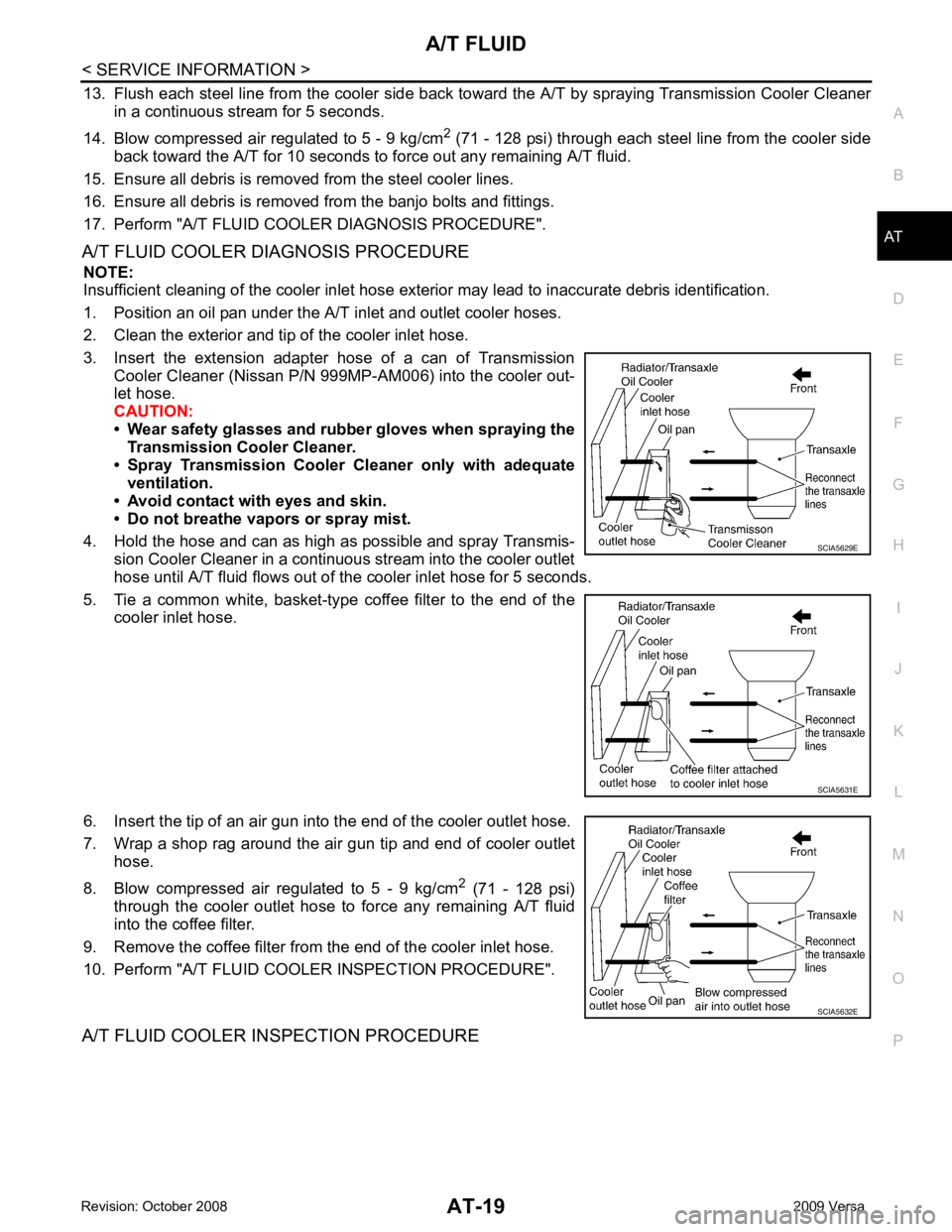
3. Insert the extension adapter hose of a can of Transmission Cooler Cleaner (Nissan P/N 999MP-AM006) into the cooler out-
let hose.
CAUTION:
• Wear safety glasses and rubber gloves when spraying the
Transmission Cooler Cleaner.
• Spray Transmission Cooler Cleaner only with adequate
ventilation.
• Avoid contact with eyes and skin.
• Do not breathe vapors or spray mist.
4. Hold the hose and can as high as possible and spray Transmis- sion Cooler Cleaner in a continuous stream into the cooler outlet
hose until A/T fluid flows out of t he cooler inlet hose for 5 seconds.
5. Tie a common white, basket-type coffee filter to the end of the cooler inlet hose.
6. Insert the tip of an air gun into the end of the cooler outlet hose.
7. Wrap a shop rag around the air gun tip and end of cooler outlet hose.
8. Blow compressed air regulated to 5 - 9 kg/cm 2
(71 - 128 psi)
through the cooler outlet hose to force any remaining A/T fluid
into the coffee filter.
9. Remove the coffee filter from the end of the cooler inlet hose.
10. Perform "A/T FLUID COOL ER INSPECTION PROCEDURE".
A/T FLUID COOLER INSPECTION PROCEDURE SCIA5629E
SCIA5631E
SCIA5632E
Page 36 of 4331
AT
N
O P
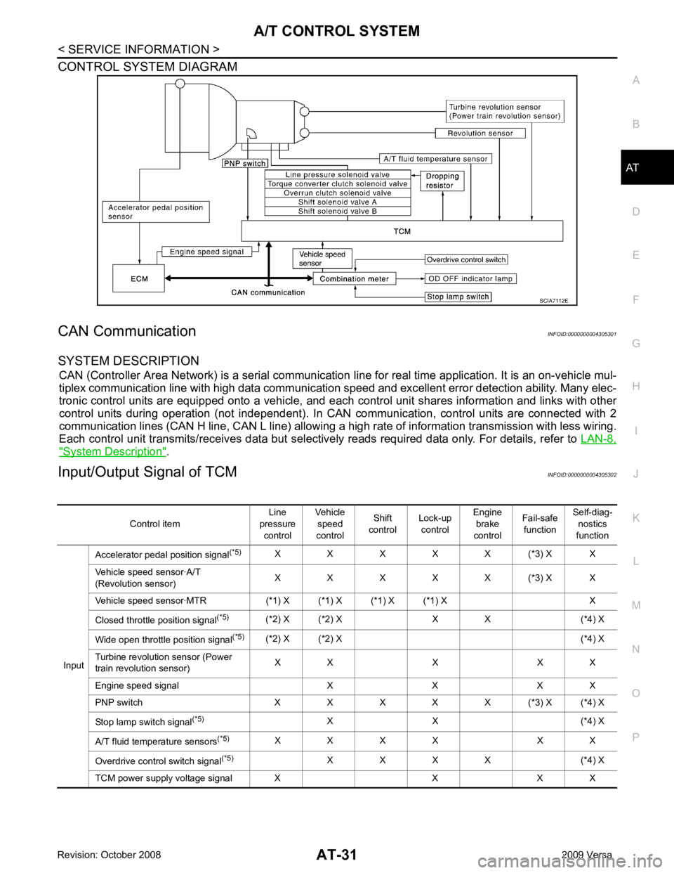
CONTROL SYSTEM DIAGRAM
CAN Communication INFOID:0000000004305301
SYSTEM DESCRIPTION CAN (Controller Area Network) is a serial communication li ne for real time application. It is an on-vehicle mul-
tiplex communication line with high data communication speed and excellent error detection ability. Many elec-
tronic control units are equipped onto a vehicle, and each control unit shares information and links with other
control units during operation (not independent). In CAN communication, control units are connected with 2
communication lines (CAN H line, CAN L line) allowing a high rate of information transmission with less wiring.
Each control unit transmits/receives data but selectively reads required data only. For details, refer to LAN-8," System Description " .
Input/Output Signal of TCM INFOID:0000000004305302
Page 44 of 4331
AT
N
O P
ON BOARD DIAGNOSTIC (OBD) SYSTEM
Introduction INFOID:0000000004305309
A/T system has two self-diagnostic systems.
The first is emission-related on boar d diagnostic system (OBD-II) performed by the TCM in combination with
the ECM. The malfunction is indicated by the MIL (malf unction indicator lamp) and is stored as a DTC in the
ECM memory but not the TCM memory.
The second is the TCM original self-diagnosis indicated by the OD OFF indicator lamp. The malfunction is
stored in the TCM memory. The detected items are ov erlapped with OBD-II self-diagnostic items. For detail,
refer to AT-79, " CONSULT-III Function (TRANSMISSION) " .
OBD-II Function for A/T System INFOID:0000000004305310
The ECM provides emission-related on board diagnostic (O BD-II) functions for the A/T system. One function
is to receive a signal from the TCM used with OBD-rela ted parts of the A/T system. The signal is sent to the
ECM when a malfunction occurs in the corresponding OBD-re lated part. The other function is to indicate a
diagnostic result by means of the MIL (malfunction indica tor lamp) on the instrument panel. Sensors, switches
and solenoid valves are used as sensing elements.
The MIL automatically illuminates in One or Two Trip Detection Logic when a malfunction is sensed in relation
to A/T system parts.
One or Two Trip Detection Logic of OBD-II INFOID:0000000004305311
ONE TRIP DETECTION LOGIC If a malfunction is sensed during the first test drive, the MIL will illuminate and the malfunction will be stored in
the ECM memory as a DTC. The TCM is not provided with such a memory function.
TWO TRIP DETECTION LOGIC When a malfunction is sensed during the first test drive, it is stored in the ECM memory as a 1st trip DTC
(diagnostic trouble code) or 1st trip freeze frame data. At this point, the MIL will not illuminate. — 1st trip
If the same malfunction as that experienced during the fi rst test drive is sensed during the second test drive,
the MIL will illuminate. — 2nd trip
The “trip” in the “One or Two Trip Detection Logic” m eans a driving mode in which self-diagnosis is performed
during vehicle operation.
OBD-II Diagnostic Trouble Code (DTC) INFOID:0000000004305312
HOW TO READ DTC AND 1ST TRIP DTC DTC and 1st trip DTC can be read by the following methods.
( with CONSULT-III or GST) CONSULT-III or GST (Generic Scan Tool) Examples: P0705, P0720 etc.
These DTC are prescribed by SAE J2012.
(CONSULT-III also displays the malfunctioning component or system.)
• 1st trip DTC No. is the same as DTC No.
• Output of the diagnostic troubl e code indicates that the indicated circuit has a malfunction. How-
ever, in case of the Mode II and GST, they do not indicate whether the malfunction is still occurring or
occurred in the past and returned to normal.
CONSULT-III can identify them as shown below, therefore, CONS ULT-III (if available) is recom-
mended.
DTC or 1st trip DTC of a malfunction is displayed in SELF-DIAGNOSTIC RESULTS mode for “ENGINE” with
CONSULT-III. Time data indicates how many times the vehicle was driven after the last detection of a DTC.
If the DTC is being detected curr ently, the time data will be “0”.
If a 1st trip DTC is stored in the ECM, the time data will be “1t”.
Freeze Frame Data and 1st Trip Freeze Frame Data The ECM has a memory function, which stores the driv ing condition such as fuel system status, calculated
load value, engine coolant temperature, short term f uel trim, long term fuel trim, engine speed and vehicle
speed at the moment the ECM detects a malfunction.
Page 45 of 4331
CONSULT-III Function " (HR16DE),
EC-604, " CONSULT-III Function (ENGINE) " (MR
Type 1) or EC-1116, " CONSULT-III F
unction (ENGINE) " (MR Type 2).
Only one set of freeze frame data (either 1st trip freez e frame data of freeze frame data) can be stored in the
ECM. 1st trip freeze frame data is stored in the ECM me mory along with the 1st trip DTC. There is no priority
for 1st trip freeze frame data and it is updated each time a different 1st trip DTC is detected. However, once
freeze frame data (2nd trip detection/MIL on) is stored in the ECM memory, 1st trip freeze frame data is no
longer stored. Remember, only one set of freeze frame data can be stored in the ECM. The ECM has the fol-
lowing priorities to update the data.
Both 1st trip freeze frame data and freeze frame dat a (along with the DTC) are cleared when the ECM mem-
ory is erased.
HOW TO ERASE DTC
The diagnostic trouble code can be erased by CONSULT- III, GST or ECM DIAGNOSTIC TEST MODE as
described following.
• If the battery cable is disconnected, the diagnosti c trouble code will be cleared within 24 hours.
• When you erase the DTC, using CONSULT-III or GS T is easier and quicker than switching the mode
selector on the ECM.
The following emission-related diagnostic information is cleared from the ECM memory when erasing DTC
related to OBD-II. For details, refer to EC-90, " Diagnosis Description " (HR16DE),
EC-542, " Emission-related
Diagnostic Information " (MR Type 1) or
EC-1052, " Emission-related Diagnostic Information " (MR Type 2).
• Diagnostic trouble codes (DTC)
• 1st trip diagnostic trou ble codes (1st trip DTC)
• Freeze frame data
• 1st trip freeze frame data
• System readiness test (SRT) codes
• Test values
HOW TO ERASE DTC (WITH CONSULT-III)
• If a DTC is displayed for both ECM and TCM, it is necessary to be erased for both ECM and TCM.
1. If the ignition switch stays ON after repair work, be sure to turn ignition switch OFF once. Wait at least 10 seconds and then turn it ON (engine stopped) again.
2. Turn CONSULT-III “ON” and touch “TRANSMISSION”.
3. Touch “SELF-DIAG RESULTS”.
4. Touch “ERASE”. (The DTC in the TCM will be erased.) Then touch “BACK” twice.
5. Touch “ENGINE”.
6. Touch “SELF-DIAG RESULTS”.
7. Touch “ERASE”. (The DTC in the ECM will be erased.)
HOW TO ERASE DTC (WITH GST)
1. If the ignition switch stays ON after repair work, be sure to turn ignition switch OFF once. Wait at least 10 seconds and then turn it ON (engine stopped) again.
2. Perform “TCM SELF-DIAGNOSTIC PROCEDURE (No Tools)”. Refer to AT-83, " Diagnosis Procedure
without CONSULT-III " . (The engine warm-up step can be skipped when performing the diagnosis only to
erase the DTC.)
3. Select Mode 4 with Generic Scan Tool (GST). For details, refer to EC-110, " Diagnosis Tool Function "
(HR16DE),
EC-612, " Generic Scan Tool (GST) Function " (MR Type 1) or
EC-1124, " Generic Scan Tool
(GST) Function " (MR Type 2).
HOW TO ERASE DTC (NO TOOLS)
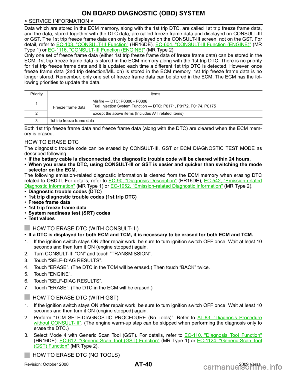
Priority Items
1 Freeze frame data Misfire — DTC: P0300 - P0306
Fuel Injection System Function — DTC: P0171, P0172, P0174, P0175
2 Except the above items (Includes A/T related items)
3 1st trip freeze frame data
Page 64 of 4331
AT
N
O P
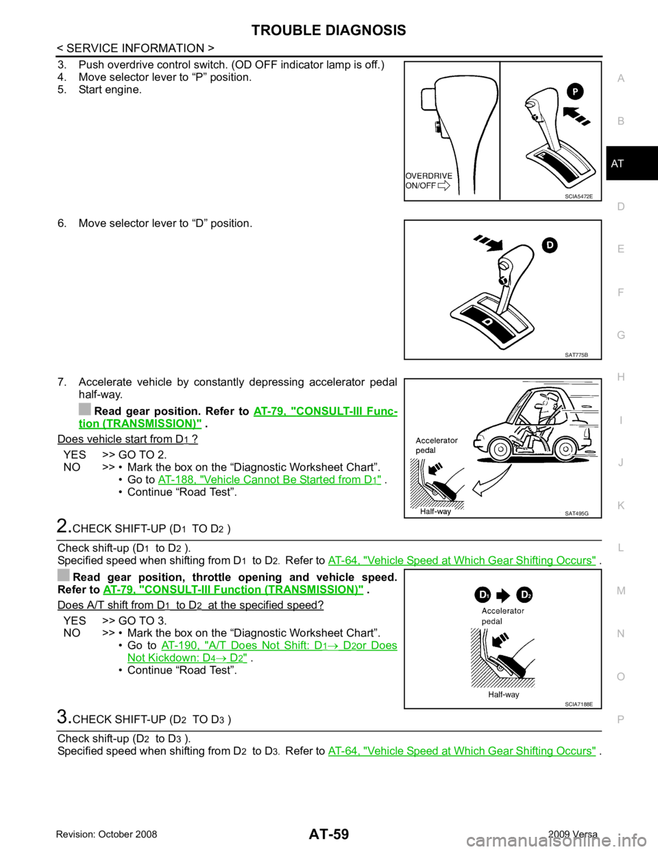
3. Push overdrive control switch. (OD OFF indicator lamp is off.)
4. Move selector lever to “P” position.
5. Start engine.
6. Move selector lever to “D” position.
7. Accelerate vehicle by constantly depressing accelerator pedal half-way.
Read gear position. Refer to AT-79, " CONSULT-III Func-
tion (TRANSMISSION) " .
Does vehicle start from D YES >> GO TO 2.
NO >> • Mark the box on the “D iagnostic Worksheet Chart”.
• Go to AT-188, " Vehicle Cannot Be Started from D .
• Continue “Road Test”. Vehicle Speed at Which Gear Shifting Occurs " .
Read gear position, throttl e opening and vehicle speed.
Refer to AT-79, " CONSULT-III Function (TRANSMISSION) " .
Does A/T shift from D YES >> GO TO 3.
NO >> • Mark the box on the “D iagnostic Worksheet Chart”.
• Go to AT-190, " A/T Does Not Shift: D
Not Kickdown: D .
• Continue “Road Test”. Vehicle Speed at Which Gear Shifting Occurs " .SAT775B
SAT495G