2009 NISSAN TIIDA schematic
[x] Cancel search: schematicPage 46 of 4331
AT
N
O P
The OD OFF indicator lamp is located on the combination meter.
1. If the ignition switch stays ON after repair work, be su re to turn ignition switch OFF once. Wait at least 10
seconds and then turn it ON (engine stopped) again.
2. Perform “TCM SELF-DIAGNOSTIC PR OCEDURE (No Tools)”. Refer to AT-83, " Diagnosis Procedure
without CONSULT-III " . (The engine warm-up step can be ski
pped when performing the diagnosis only to
erase the DTC.)
3. Perform “OBD-II SELF-DIAGNOSTIC PROCEDURE (No tools)”. Refer to EC-90, " Diagnosis Description "
(HR16DE),
EC-542, " Emission-related Diagnostic Information " (MR Type 1) or
EC-1052, " Emission-
related Diagnostic Information " (MR Type 2).
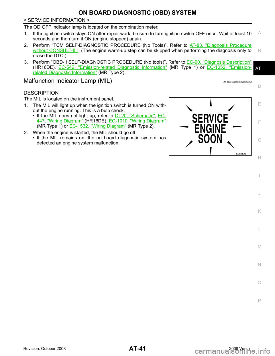
Malfunction Indicator Lamp (MIL) INFOID:0000000004305313
DESCRIPTION The MIL is located on the instrument panel.
1. The MIL will light up when the ignition switch is turned ON with- out the engine running. This is a bulb check.
• If the MIL does not light up, refer to DI-20, " Schematic " ,
EC- 447, " Wiring Diagram " (HR16DE),
EC-1010, " Wiring Diagram "
(MR Type 1) or
EC-1532, " Wiring Diagram " (MR Type 2).
2. When the engine is start ed, the MIL should go off.
• If the MIL remains on, the on board diagnostic system has
detected an engine system malfunction.
Page 385 of 4331
AV
N
O P
CONTENTS
AUDIO, VISUAL, NAVIGATION & TELEPHONE SYS-
TEM
SERVICE INFORMATION .. ..........................2
PRECAUTIONS .............................................. .....2
Precaution for Supplemental Restraint System
(SRS) "AIR BAG" and "SEAT BELT PRE-TEN-
SIONER" ............................................................. ......
2
PREPARATION .............................................. .....3
Commercial Service Tool .................................... ......3
AUDIO ............................................................ .....4
Component Parts Location .................................. ......4
System Description ............................................. ......4
Schematic ........................................................... ......6
Wiring Diagram - AUDIO - ................................... ......8
Audio Unit (Base System) Harness Connector
Terminal Layout .................................................. ....
16
Terminal and Reference Value for Audio Unit
(Base System) ..................................................... ....
16
Audio Unit (Mid Level and Premium System) Har-
ness Connector Terminal Layout ........................ ....
17
Terminal and Reference Value for Audio Unit (Mid
Level and Premium System) ............................... ....
17
Subwoofer Harness Connector Terminal Layout
(Premium Audio System) .................................... ....
20
Terminal and Reference Value for Subwoofer
(Premium Audio System) .................................... ....
20
Satellite Radio Tuner Ha rness Connector Termi-
nal Layout ............................................................ ....
20
Terminal and Reference Value for Satellite Radio
Tuner ................................................................... ....
21
Trouble Diagnosis ............................................... ....21
Noise Inspection .................................................. ....22
Power Supply Circuit Inspection ......................... ....23
Satellite Radio Tuner (Fac tory Installed) Power
and Ground Supply Circuit Inspection ................. ....
24
Satellite Radio Tuner (Fac tory Installed) Commu-
nication Circuit Inspection ................................... ....
25
Satellite Radio Tuner (Fac tory Installed) Left
Channel Audio Signal Circuit Inspection ............. ....
27 Satellite Radio Tuner (Fac
tory Installed) Right
Channel Audio Signal Circuit Inspection ............. ....
27
Steering Switch Check (With Bluetooth) .............. ....28
Sound Is Not Heard from Front Door Speaker
(Base System) ..................................................... ....
30
Sound Is Not Heard from Rear Door Speaker
(Base System) ..................................................... ....
31
Sound Is Not Heard from Front Door Speaker or
Tweeter (Mid Level and Premium System) .............
32
Sound Is Not Heard from Rear Door Speaker (Mid
Level and Premium System) ............................... ....
33
Sound Is Not Heard from Subwoofer (Premium
System) ............................................................... ....
35
Removal and Installation ..................................... ....37
AUDIO ANTENNA ............................................. 42
Location of Antenna ............................................. ....42
Removal and Installation of Roof Antenna ..............42
TELEPHONE ..................................................... 44
Component Parts and Harness Connector Loca-
tion ....................................................................... ....
44
System Description .............................................. ....44
Wiring Diagram - H/PHON - ................................ ....46
Bluetooth Control Unit Harness Connector Termi-
nal Layout ............................................................ ....
48
Terminal and Reference Value for Bluetooth Con-
trol Unit ................................................................ ....
48
Bluetooth Control Unit Se lf-Diagnosis Function ......49
Workflow .............................................................. ....50
Power Supply and Ground Circuit Inspection for
Bluetooth Control Unit .. ...........................................
50
Basic Inspection of Hands-Free Phone ............... ....51
Steering Wheel Audio Co ntrol Switch Does Not
Operate ................................................................ ....
52
Voice Activated Control Fu nction Does Not Oper-
ate ........................................................................ ....
53
Removal and Installation ..................................... ....55
Page 443 of 4331
BCS
N
O P
CONTENTS
BODY CONTROL SYSTEM
SERVICE INFORMATION .. ..........................2
PRECAUTIONS .............................................. .....2
Precaution for Supplemental Restraint System
(SRS) "AIR BAG" and "SEAT BELT PRE-TEN-
SIONER" ............................................................. ......
2
BCM (BODY CONTROL MODULE) ............... .....3
System Description ............................................. ......3
CAN Communication System Description ........... ......7
Schematic ........................................................... ......8 BCM Terminal Arrangement ................................
....10
Terminal and Reference Value for BCM ..................11
BCM Power Supply and Ground Circuit Inspection ....15
CONSULT-III Function (B CM) .................................16
CAN Communication Inspection Using CON-
SULT-III (Self-Diagnosis) ..................................... ....
17
Configuration ....................................................... ....18
Removal and Installation of BCM ........................ ....18
Page 457 of 4331
BCS
N
O P
1: With Intelligent Key
2: Without Intelligent Key
3: Hatchback without Intelligent Key
4: Sedan without Intelligent Key
5: Hatchback
6: Sedan
7: With power door locks
8: With power windows
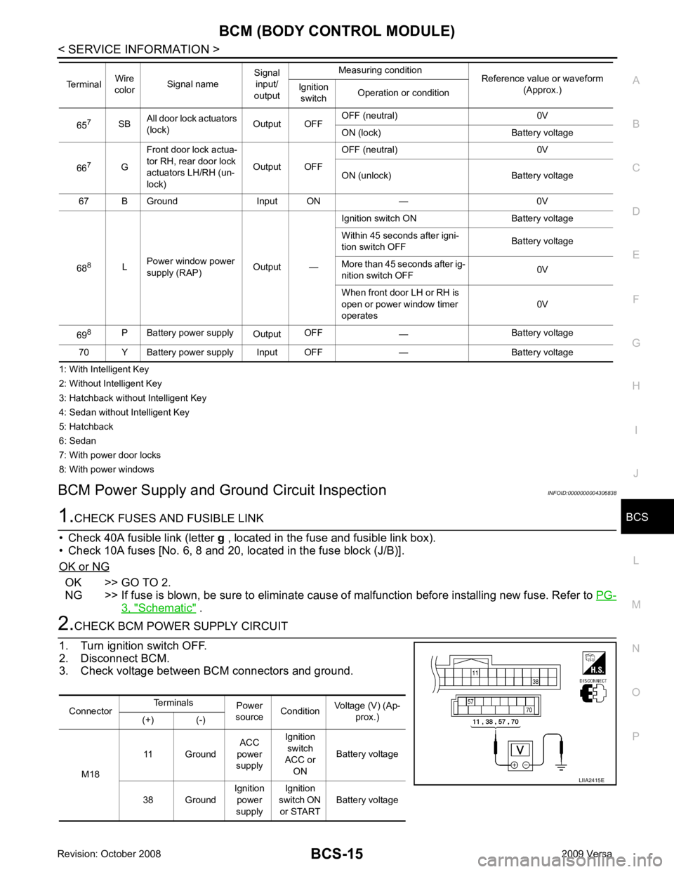
BCM Power Supply and Gr ound Circuit Inspection INFOID:0000000004306838OK >> GO TO 2.
NG >> If fuse is blown, be sure to eliminate caus e of malfunction before installing new fuse. Refer to PG-3, " Schematic " .
Connector
Terminals
Power
source Condition Voltage (V) (Ap-
prox.)
(+) (-)
M18 11 Ground
ACC
power
supply Ignition
switch
ACC or
ON Battery voltage
38 Ground Ignition
power
supply Ignition
switch ON or START Battery voltage
Page 462 of 4331
BL
N
O P
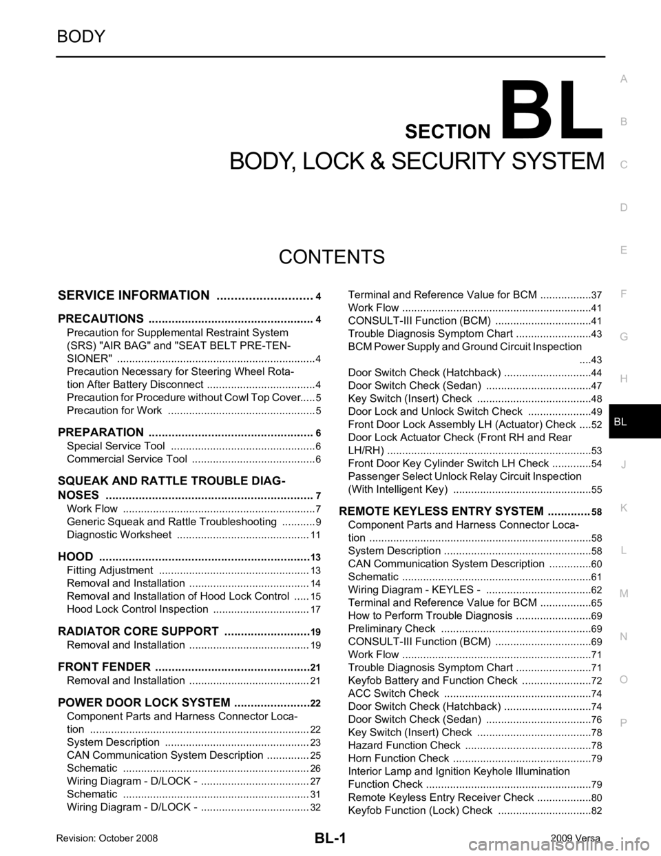
CONTENTS
BODY, LOCK & SECURITY SYSTEM
SERVICE INFORMATION .. ..........................4
PRECAUTIONS .............................................. .....4
Precaution for Supplemental Restraint System
(SRS) "AIR BAG" and "SEAT BELT PRE-TEN-
SIONER" ............................................................. ......
4
Precaution Necessary fo r Steering Wheel Rota-
tion After Battery Disconnect ............................... ......
4
Precaution for Procedure without Cowl Top Cover ......5
Precaution for Work ............................................ ......5
PREPARATION .............................................. .....6
Special Service Tool ........................................... ......6
Commercial Service Tool .................................... ......6
SQUEAK AND RATTLE TROUBLE DIAG-
NOSES ........................ ........................................7
Work Flow ........................................................... ......7
Generic Squeak and Rattle Troubleshooting ...... ......9
Diagnostic Worksheet ......................................... ....11
HOOD ............................................................. ....13
Fitting Adjustment ............................................... ....13
Removal and Installation .........................................14
Removal and Installation of Hood Lock Control .. ....15
Hood Lock Control Inspec tion .................................17
RADIATOR CORE SUPPORT ....................... ....19
Removal and Installation .........................................19
FRONT FENDER ............................................ ....21
Removal and Installation .........................................21
POWER DOOR LOCK SYSTEM .................... ....22
Component Parts and Harness Connector Loca-
tion ...................................................................... ....
22
System Description ............................................. ....23
CAN Communication System Description ........... ....25
Schematic ........................................................... ....26
Wiring Diagram - D/LOCK - ................................. ....27
Schematic ........................................................... ....31
Wiring Diagram - D/LOCK - ................................. ....32 Terminal and Reference
Value for BCM ..................37
Work Flow ............................................................ ....41
CONSULT-III Function (B CM) .................................41
Trouble Diagnosis Symptom Chart ...................... ....43
BCM Power Supply and Ground Circuit Inspection ....43
Door Switch Check (Hatchback) .......................... ....44
Door Switch Check (Sedan) ................................ ....47
Key Switch (Insert) Check ................................... ....48
Door Lock and Unlock Switch Check .................. ....49
Front Door Lock Assembly LH (Actuator) Check .....52
Door Lock Actuator Check (Front RH and Rear
LH/RH) ................................................................. ....
53
Front Door Key Cylinder S witch LH Check ..............54
Passenger Select Unlock Relay Circuit Inspection
(With Intelligent Key) ........................................... ....
55
REMOTE KEYLESS ENTRY SYSTEM ............. 58
Component Parts and Harness Connector Loca-
tion ....................................................................... ....
58
System Description .............................................. ....58
CAN Communication System Description ........... ....60
Schematic ............................................................ ....61
Wiring Diagram - KEYLES - ................................ ....62
Terminal and Reference Value for BCM ..................65
How to Perform Trouble Diagnosis ...................... ....69
Preliminary Check ............................................... ....69
CONSULT-III Function (B CM) .................................69
Work Flow ............................................................ ....71
Trouble Diagnosis Symptom Chart ...................... ....71
Keyfob Battery and Function Check .................... ....72
ACC Switch Check .............................................. ....74
Door Switch Check (Hatchback) .......................... ....74
Door Switch Check (Sedan) ................................ ....76
Key Switch (Insert) Check ................................... ....78
Hazard Function Check ....................................... ....78
Horn Function Check ........................................... ....79
Interior Lamp and Ignition Keyhole Illumination
Function Check .................................................... ....
79
Remote Keyless Entry Rece iver Check ...................80
Keyfob Function (Lock) Check ............................ ....82
Page 464 of 4331
BL
N
O P
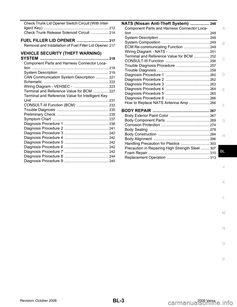
Check Trunk Lid Opener S
witch Circuit (With Intel-
ligent Key) ........................................................... ..
212
Check Trunk Release Solenoid Circuit ............... ..214
FUEL FILLER LID OPENER .......................... ..217
Removal and Installation of Fuel Filler Lid Opener ..217
VEHICLE SECURITY (THEFT WARNING)
SYSTEM ......................................................... ..
218
Component Parts and Harness Connector Loca-
tion ...................................................................... ..
218
System Description ............................................. ..219
CAN Communication System Description ........... ..221
Schematic ........................................................... ..222
Wiring Diagram - VEHSEC - ............................... ..223
Terminal and Reference Value for BCM ............. ..227
Terminal and Re ference Value for Intelligent Key
Unit ...................................................................... ..
231
CONSULT-III Function (BCM) ............................. ..233
Trouble Diagnosis ............................................... ..235
Preliminary Check ............................................... ..235
Symptom Chart ................................................... ..237
Diagnosis Procedure 1 ........................................ ..238
Diagnosis Procedure 2 ........................................ ..241
Diagnosis Procedure 3 ........................................ ..242
Diagnosis Procedure 4 ........................................ ..242
Diagnosis Procedure 5 ........................................ ..242
Diagnosis Procedure 6 ........................................ ..242
Diagnosis Procedure 7 ........................................ ..242
Diagnosis Procedure 8 ........................................ ..244
Diagnosis Procedure 9 ........................................ ..245 NATS (Nissan Anti-Theft System) ................
248
Component Parts and Harness Connector Loca-
tion ....................................................................... ..
248
System Description .............................................. ..248
System Composition ............................................ ..249
ECM Re-communicating Function ....................... ..249
Wiring Diagram - NATS - ..................................... ..251
Terminal and Reference Value for BCM ................252
CONSULT-III Function ........................................ ..256
Trouble Diagnosis Procedure .............................. ..257
Trouble Diagnosis ................................................ ..259
Diagnosis Procedure 1 ........................................ ..260
Diagnosis Procedure 2 ........................................ ..262
Diagnosis Procedure 3 ........................................ ..263
Diagnosis Procedure 4 ........................................ ..264
Diagnosis Procedure 5 ........................................ ..265
Diagnosis Procedure 6 ........................................ ..266
How to Replace NATS Antenna Amp .................. ..266
BODY REPAIR ................................................ 267
Body Exterior Paint Color .................................... ..267
Body Component Parts ....................................... ..269
Corrosion Protection ............................................ ..274
Body Sealing ....................................................... ..278
Body Construction ............................................... ..284
Body Alignment ................................................... ..286
Handling Precaution for Plastics .......................... ..303
Precaution in Repairing High Strength Steel ....... ..307
Foam Repair ........................................................ ..310
Replacement Operation ....................................... ..313
Page 492 of 4331
BL
N
O P
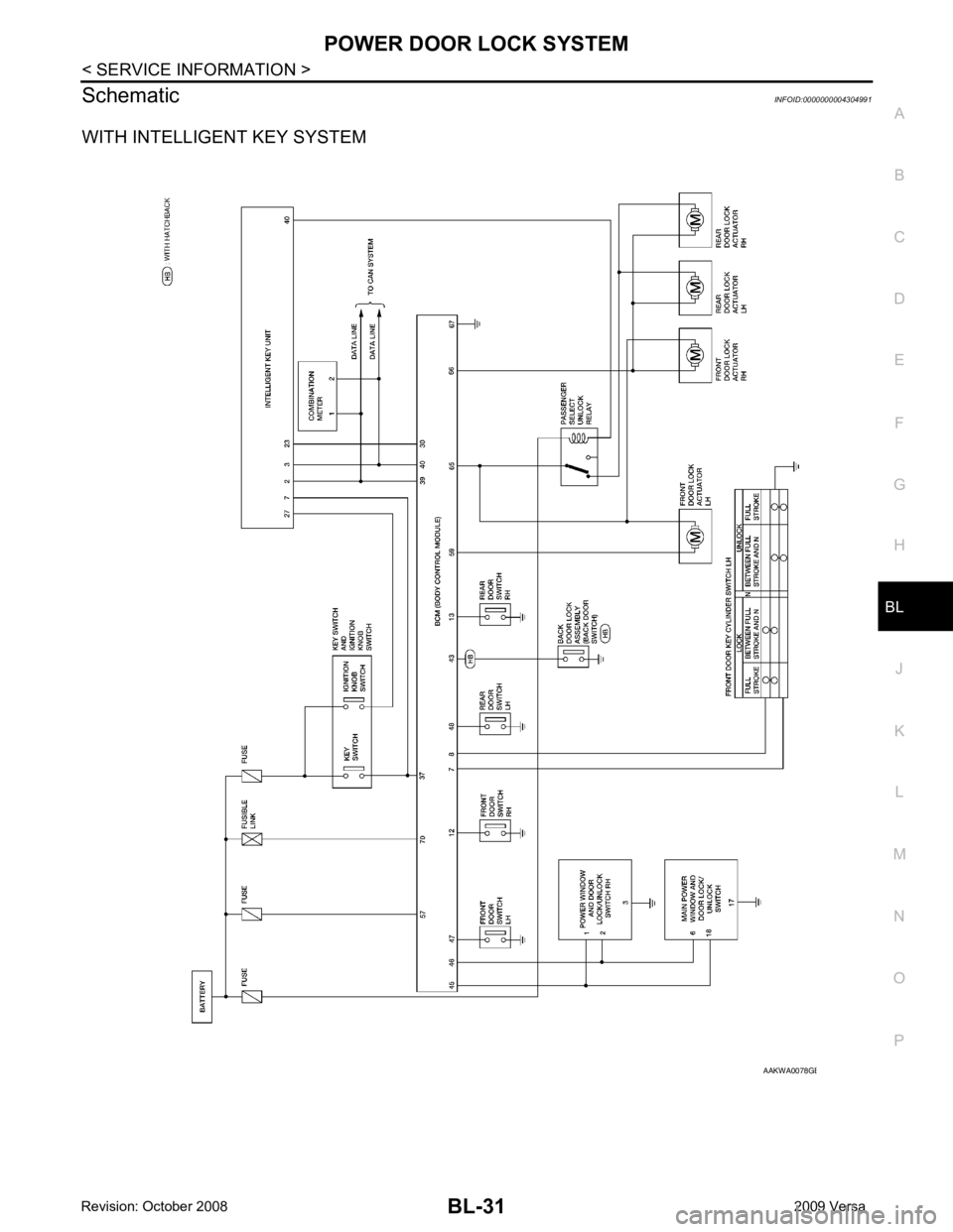
Schematic
INFOID:0000000004304991
WITH INTELLIGENT KEY SYSTEM B
Page 504 of 4331
BL
N
O P
*: With Remote Keyless Entry system
**: With Intelligent Key system
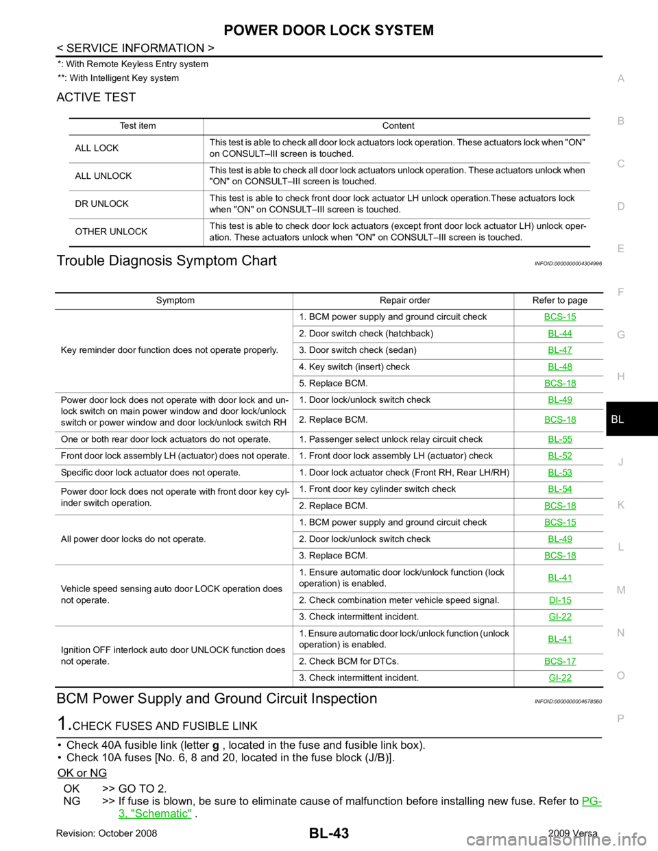
ACTIVE TEST
Trouble Diagnosis Symptom Chart INFOID:0000000004304996
BCM Power Supply and Gr ound Circuit Inspection INFOID:0000000004678560OK >> GO TO 2.
NG >> If fuse is blown, be sure to eliminate caus e of malfunction before installing new fuse. Refer to PG-3, " Schematic " .
Test item Content
ALL LOCK This test is able to check all door lock actuators lock operation. These actuators lock when "ON"
on CONSULT–III screen is touched.
ALL UNLOCK This test is able to check all door lock actuators unlock operation. These actuators unlock when
"ON" on CONSULT–III screen is touched.
DR UNLOCK This test is able to check front door lock actuator LH unlock operation.These actuators lock
when "ON" on CONSULT– III screen is touched.
OTHER UNLOCK This test is able to check door lock actuators (except front door lock actuator LH) unlock oper-
ation. These actuators unlock when "ON" on CONSULT–III screen is touched. Symptom Repair order Refer to page
Key reminder door function does not operate properly. 1. BCM power supply and ground circuit check
BCS-15 2. Door switch check (hatchback)
BL-44 3. Door switch check (sedan)
BL-47 4. Key switch (insert) check
BL-48 5. Replace BCM.
BCS-18Power door lock does not operate with door lock and un-
lock switch on main power window and door lock/unlock
switch or power window and door lock/unlock switch RH 1. Door lock/unlock switch check
BL-49 2. Replace BCM.
BCS-18One or both rear door lock actuators do not operate. 1. Passenger select unlock relay circuit check
BL-55Front door lock assembly LH (actuator) does not operate. 1. Front door lock assembly LH (actuator) check
BL-52Specific door lock actuator does not operate. 1. Door lock actuator check (Front RH, Rear LH/RH)
BL-53Power door lock does not operate with front door key cyl-
inder switch operation. 1. Front door key cylinder switch check
BL-54 2. Replace BCM.
BCS-18All power door locks do not operate.
1. BCM power supply and ground circuit check
BCS-15 2. Door lock/unlock switch check
BL-49 3. Replace BCM.
BCS-18Vehicle speed sensing auto door LOCK operation does
not operate. 1. Ensure automatic door lock/unlock function (lock
operation) is enabled. BL-41 2. Check combination meter vehicle speed signal.
DI-15 3. Check intermittent incident.
GI-22Ignition OFF interlock auto door UNLOCK function does
not operate. 1. Ensure automatic door lock/unlock function (unlock
operation) is enabled. BL-41 2. Check BCM for DTCs.
BCS-17 3. Check intermittent incident.
GI-22