2009 NISSAN TIIDA front bumper removal and installation
[x] Cancel search: front bumper removal and installationPage 470 of 4331
BL
N
O P
SILICONE GREASE
Used instead of UHMW tape that will be visible or not fit.
Note: Will only last a few months.
SILICONE SPRAY
Use when grease cannot be applied.
DUCT TAPE
Use to eliminate movement.
CONFIRM THE REPAIR Confirm that the cause of a noise is repaired by test driving the vehicle. Operate the vehicle under the same
conditions as when the noise originally occurred. Refer to the notes on the Diagnostic Worksheet.
Generic Squeak and Rattle Troubleshooting INFOID:0000000004304978
Refer to Table of Contents for specific component removal and installation information.
INSTRUMENT PANEL Most incidents are caused by contact and movement between:
1. The cluster lid A and instrument panel
2. Acrylic lens and combination meter housing
3. Instrument panel to front pillar garnish
4. Instrument panel to windshield
5. Instrument panel mounting pins
6. Wiring harnesses behind the combination meter
7. A/C defroster duct and duct joint
These incidents can usually be located by tapping or moving the components to duplicate the noise or by
pressing on the components while driving to stop the noi se. Most of these incidents can be repaired by apply-
ing felt cloth tape or silicone spray (in hard to reach areas). Urethane pads can be used to insulate wiring har-
ness.
CAUTION:
Do not use silicone spray to isolate a squeak or ra ttle. If you saturate the area with silicone, you will
not be able to recheck the repair.
CENTER CONSOLE Components to pay attention to include:
1. Shifter assembly cover to finisher
2. A/C control unit and cluster lid C
3. Wiring harnesses behind audio and A/C control unit
The instrument panel repair and isolation pr ocedures also apply to the center console.
DOORS Pay attention to the:
1. Finisher and inner panel making a slapping noise
2. Inside handle escutcheon to door finisher
3. Wiring harnesses tapping
4. Door striker out of alignment causing a popping noise on starts and stops
Tapping or moving the components or pressing on them wh ile driving to duplicate the conditions can isolate
many of these incidents. You can usually insulate the ar eas with felt cloth tape or insulator foam blocks from
the NISSAN Squeak and Rattle Kit (J-43980) to repair the noise.
TRUNK Trunk noises are often caused by a loose jack or loose items put into the trunk by the owner.
In addition look for:
1. Trunk lid bumpers out of adjustment
2. Trunk lid striker out of adjustment
3. The trunk lid torsion bars knocking together
4. A loose license plate or bracket
Page 480 of 4331
BL
N
O P
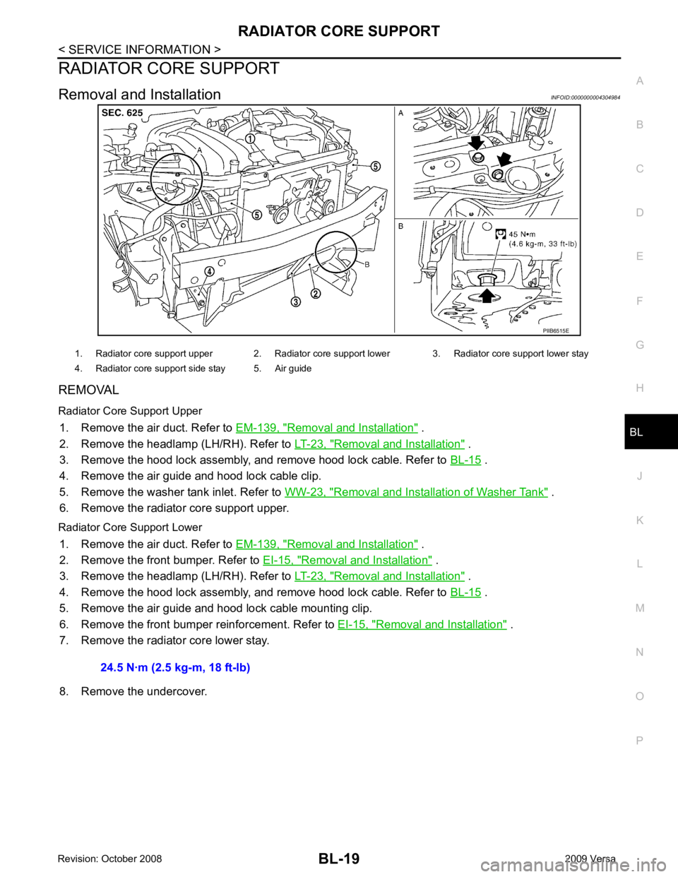
RADIATOR CORE SUPPORT
Removal and Installation INFOID:0000000004304984
REMOVAL
Radiator Core Support Upper 1. Remove the air duct. Refer to EM-139, " Removal and Installation " .
2. Remove the headlamp (LH/RH). Refer to LT-23, " Removal and Installation " .
3. Remove the hood lock assembly, and remove hood lock cable. Refer to BL-15 .
4. Remove the air guide and hood lock cable clip.
5. Remove the washer tank inlet. Refer to WW-23, " Removal and Installation of Washer Tank " .
6. Remove the radiator core support upper.
Radiator Core Support Lower 1. Remove the air duct. Refer to EM-139, " Removal and Installation " .
2. Remove the front bumper. Refer to EI-15, " Removal and Installation " .
3. Remove the headlamp (LH/RH). Refer to LT-23, " Removal and Installation " .
4. Remove the hood lock assembly, and remove hood lock cable. Refer to BL-15 .
5. Remove the air guide and hood lock cable mounting clip.
6. Remove the front bumper reinforcement. Refer to EI-15, " Removal and Installation " .
7. Remove the radiator core lower stay.
8. Remove the undercover.
Page 607 of 4331
BL-146< SERVICE INFORMATION >
INTELLIGENT KEY SYSTEM
OK or NG OK >> Replace rear bumper antenna.
NG >> Replace Intelligent Key unit. Refer to BL-158, " Removal and Installation of Intelligent Key Unit " .
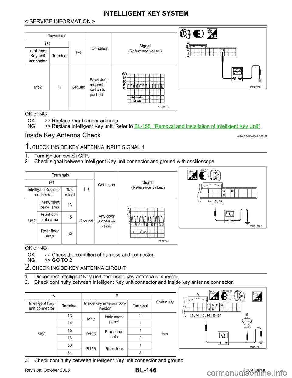
Inside Key Antenna Check INFOID:00000000043050591.
CHECK INSIDE KEY ANTENNA INPUT SIGNAL 1
1. Turn ignition switch OFF.
2. Check signal between Intelligent Key unit connector and ground with oscilloscope.
OK or NG OK >> Check the condition of harness and connector.
NG >> GO TO 2 2.
CHECK INSIDE KEY ANTENNA CIRCUIT
1. Disconnect Intelligent Key unit and inside key antenna connector.
2. Check continuity between Intelligent Key unit connector and inside key antenna connector.
3. Check continuity between Intelligent Key unit connector and ground. Terminals
Condition Signal
(Reference value.)
(+)
(–)
Intelligent
Key unit
connector Terminal
M52 17 Ground Back door
request
switch is
pushed PIIB6628E
SIIA1910J
Terminals ConditionSignal
(Reference value.)
(+)
(–)
Intelligent Key unit
connector Ter-
minal
M52 Instrument
panel area 13
Ground Any door
is open →
close
Front con-
sole area 15
Rear floor area 33 WIIA1200E
PIIB5502J
A B Continuity
Intelligent Key
unit connector TerminalInside key antenna con-
nector Terminal
M52 13
M10Instrument
panel 2
Yes
14 1
15 B125Front con-
sole 1
16 2
33 B126 Rear floor 1
34 2 WIIA1254E
Page 2892 of 4331
EI
N
O P
CONTENTS
EXTERIOR & INTERIOR
PRECAUTION ....... ........................................3
PRECAUTIONS .............................................. .....3
Precaution for Supplemental Restraint System
(SRS) "AIR BAG" and "SEAT BELT PRE-TEN-
SIONER" ............................................................. ......
3
Precaution Necessary fo r Steering Wheel Rota-
tion After Battery Disconnect ............................... ......
3
Precaution ........................................................... ......4
PREPARATION .... ........................................5
PREPARATION .............................................. .....5
Special Service Tool ........................................... ......5
Commercial Service Tool .................................... ......5
SYMPTOM DIAGNOSIS ..... ..........................6
SQUEAK AND RATTLE TROUBLE DIAGNO-
SIS .................................................................. .....6
Work Flow ........................................................... ......6
Generic Squeak and Rattle Troubleshooting ...... ......8
Diagnostic Worksheet ......................................... ....10
CLIP AND FASTENER ................................... ....12
Description .......................................................... ....12
ON-VEHICLE REPAIR .... .............................15
FRONT BUMPER ........................................... ....15
Removal and Installation .........................................15
REAR BUMPER ............................................. ....17
Component .......................................................... ....17
Removal and Installation - Hatchback .....................18
Removal and Installation - Sedan ....................... ....19
FRONT GRILLE ............................................. ....21
Removal and Installation .........................................21
COWL TOP ..................................................... ....22
Removal and Installation .........................................22 FENDER PROTECTOR ....................................
24
Component .......................................................... ....24
Removal and Installation ..................................... ....24
ROOF SIDE MOLDING ..................................... 25
Component .......................................................... ....25
Removal and Installation ..................................... ....25
DOOR OUTSIDE MOLDING ............................. 27
Component .......................................................... ....27
Removal and Installation ..................................... ....28
CENTER MUD GUARD ..................................... 30
Removal and Installation ..................................... ....30
TRUNK LID FINISHER ...................................... 31
Removal and Installation ..................................... ....31
REAR AIR SPOILER ......................................... 32
Removal and Installation ..................................... ....32
DOOR FINISHER .............................................. 34
Removal and Installation ..................................... ....34
BACK DOOR TRIM ........................................... 38
Removal and Installation ..................................... ....38
BODY SIDE TRIM ............................................. 39
Component .......................................................... ....39
Removal and Installation ..................................... ....40
REAR PARCEL SHELF FINISHER .................. 44
Removal and Installation ..................................... ....44
FLOOR TRIM .................................................... 45
Removal and Installation ..................................... ....45
HEADLINING .................................................... 47
Component .......................................................... ....47
Removal and Installation - Hatchback ................. ....49
Removal and Installation - Sedan ........................ ....51
LUGGAGE FLOOR TRIM ................................. 53
Page 2906 of 4331
EI
N
O P
ON-VEHICLE REPAIR
FRONT BUMPER
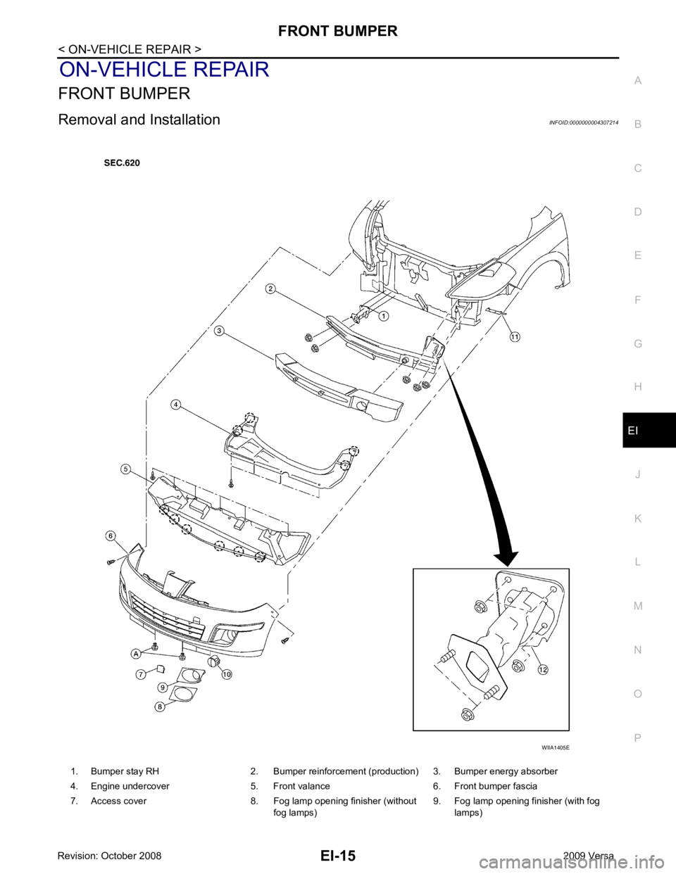
Removal and Installation INFOID:0000000004307214
1. Bumper stay RH 2. Bumper reinforcement (production) 3. Bumper energy absorber
4. Engine undercover 5. Front valance 6. Front bumper fascia
7. Access cover 8. Fog lamp opening finisher (without fog lamps)9. Fog lamp opening finisher (with fog
lamps)
Page 2907 of 4331
.
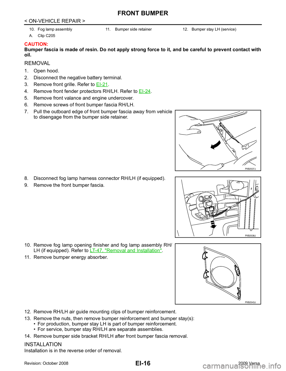
4. Remove front fender protectors RH/LH. Refer to EI-24 .
5. Remove front valance and engine undercover.
6. Remove screws of front bumper fascia RH/LH.
7. Pull the outboard edge of front bumper fascia away from vehicle to disengage from the bumper side retainer.
8. Disconnect fog lamp harness connector RH/LH (if equipped).
9. Remove the front bumper fascia.
10. Remove fog lamp opening finisher and fog lamp assembly RH/ LH (if equipped). Refer to LT-47, " Removal and Installation " .
11. Remove bumper energy absorber.
12. Remove RH/LH air guide mounting clips of bumper reinforcement.
13. Remove the nuts, then remove bumper reinforcement and bumper stay(s): • For production, bumper stay LH is part of bumper reinforcement.
• For service, bumper stay RH/LH are separate assemblies.
14. Remove bumper side bracket RH/LH after front bumper fascia removal.
INSTALLATION
Installation is in the reverse order of removal. 10. Fog lamp assembly 11. Bumper side retainer 12. Bumper stay LH (service)
A. Clip C205 PIIB2543J
Page 2910 of 4331
EI
N
O P
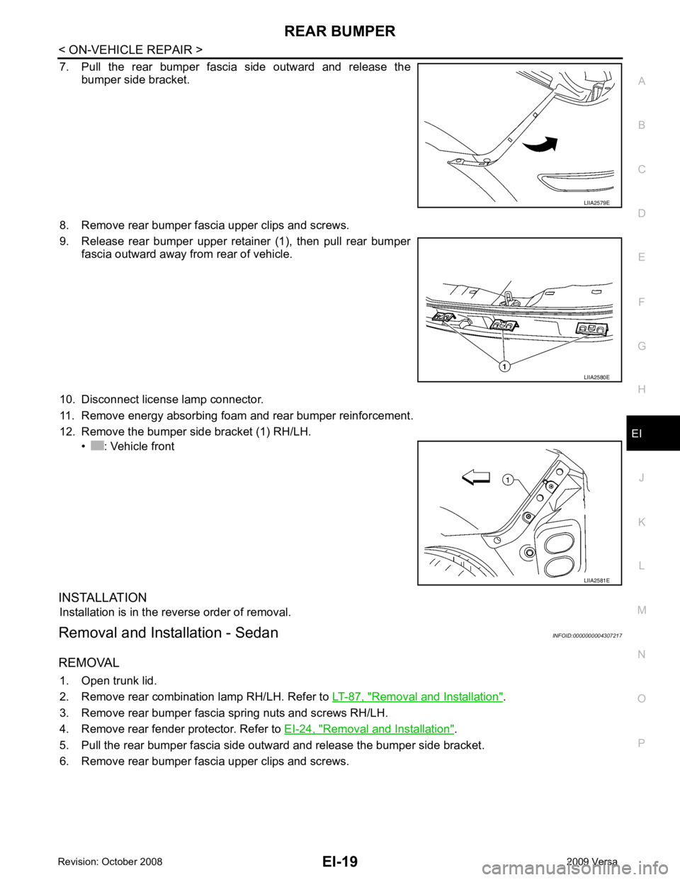
7. Pull the rear bumper fascia side outward and release the
bumper side bracket.
8. Remove rear bumper fascia upper clips and screws.
9. Release rear bumper upper retainer (1), then pull rear bumper fascia outward away from rear of vehicle.
10. Disconnect license lamp connector.
11. Remove energy absorbing foam and rear bumper reinforcement.
12. Remove the bumper side bracket (1) RH/LH. • : Vehicle front
INSTALLATION Installation is in the reverse order of removal.
Removal and Installation - Sedan INFOID:0000000004307217
REMOVAL 1. Open trunk lid.
2. Remove rear combination lamp RH/LH. Refer to LT-87, " Removal and Installation " .
3. Remove rear bumper fascia spring nuts and screws RH/LH.
4. Remove rear fender protector. Refer to EI-24, " Removal and Installation " .
5. Pull the rear bumper fascia side outward and release the bumper side bracket.
6. Remove rear bumper fascia upper clips and screws. LIIA2580E
Page 2911 of 4331
EI-20< ON-VEHICLE REPAIR >
REAR BUMPER
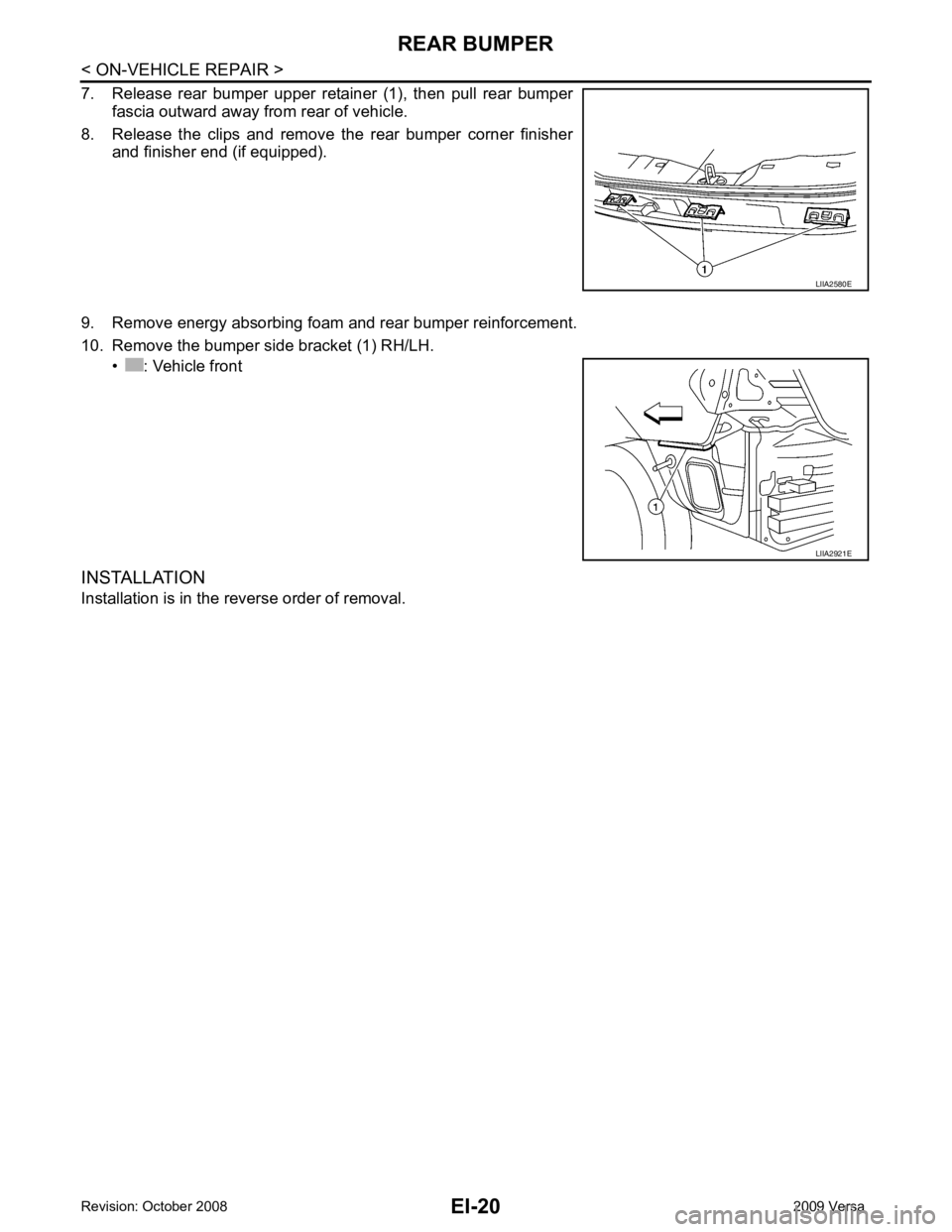
7. Release rear bumper upper retainer (1), then pull rear bumper fascia outward away from rear of vehicle.
8. Release the clips and remove the rear bumper corner finisher and finisher end (if equipped).
9. Remove energy absorbing foam and rear bumper reinforcement.
10. Remove the bumper side bracket (1) RH/LH. • : Vehicle front
INSTALLATION
Installation is in the reverse order of removal. LIIA2580E
LIIA2921E