Page 504 of 4331
BL
N
O P
*: With Remote Keyless Entry system
**: With Intelligent Key system
ACTIVE TEST
Trouble Diagnosis Symptom Chart INFOID:0000000004304996
BCM Power Supply and Gr ound Circuit Inspection INFOID:0000000004678560OK >> GO TO 2.
NG >> If fuse is blown, be sure to eliminate caus e of malfunction before installing new fuse. Refer to PG-3, " Schematic " .
Test item Content
ALL LOCK This test is able to check all door lock actuators lock operation. These actuators lock when "ON"
on CONSULT–III screen is touched.
ALL UNLOCK This test is able to check all door lock actuators unlock operation. These actuators unlock when
"ON" on CONSULT–III screen is touched.
DR UNLOCK This test is able to check front door lock actuator LH unlock operation.These actuators lock
when "ON" on CONSULT– III screen is touched.
OTHER UNLOCK This test is able to check door lock actuators (except front door lock actuator LH) unlock oper-
ation. These actuators unlock when "ON" on CONSULT–III screen is touched. Symptom Repair order Refer to page
Key reminder door function does not operate properly. 1. BCM power supply and ground circuit check
BCS-15 2. Door switch check (hatchback)
BL-44 3. Door switch check (sedan)
BL-47 4. Key switch (insert) check
BL-48 5. Replace BCM.
BCS-18Power door lock does not operate with door lock and un-
lock switch on main power window and door lock/unlock
switch or power window and door lock/unlock switch RH 1. Door lock/unlock switch check
BL-49 2. Replace BCM.
BCS-18One or both rear door lock actuators do not operate. 1. Passenger select unlock relay circuit check
BL-55Front door lock assembly LH (actuator) does not operate. 1. Front door lock assembly LH (actuator) check
BL-52Specific door lock actuator does not operate. 1. Door lock actuator check (Front RH, Rear LH/RH)
BL-53Power door lock does not operate with front door key cyl-
inder switch operation. 1. Front door key cylinder switch check
BL-54 2. Replace BCM.
BCS-18All power door locks do not operate.
1. BCM power supply and ground circuit check
BCS-15 2. Door lock/unlock switch check
BL-49 3. Replace BCM.
BCS-18Vehicle speed sensing auto door LOCK operation does
not operate. 1. Ensure automatic door lock/unlock function (lock
operation) is enabled. BL-41 2. Check combination meter vehicle speed signal.
DI-15 3. Check intermittent incident.
GI-22Ignition OFF interlock auto door UNLOCK function does
not operate. 1. Ensure automatic door lock/unlock function (unlock
operation) is enabled. BL-41 2. Check BCM for DTCs.
BCS-17 3. Check intermittent incident.
GI-22
Page 655 of 4331
.
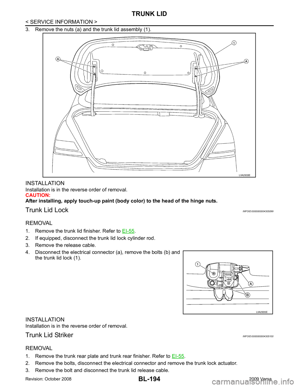
2. If equipped, disconnect the trunk lid lock cylinder rod.
3. Remove the release cable.
4. Disconnect the electrical connector (a), remove the bolts (b) and
the trunk lid lock (1).
INSTALLATION
Installation is in the reverse order of removal.
Trunk Lid Striker INFOID:0000000004305100
REMOVAL
1. Remove the trunk rear plate and trunk rear finisher. Refer to EI-55 .
2. Remove the bolts, disconnect the electrical connector and remove the trunk lock actuator.
3. Remove the bolt and disconnect the trunk lid release cable. LIIA2935E
Page 810 of 4331
Component " (front disc brake),
BR-33, " Compo-
nent " (rear drum brake).
6. Following the steps 1 to 5 above, with master cylinder reservoir tank filled at least half way, bleed air from
the rear right, front left, rear left, and front right brake, in that order.
Page 837 of 4331
BR
N
O P
5. Connect the parking brake rear cable to the operating lever.
6. Install the shoe assembly. After assembly, be sure that each part is installed properly. CAUTION:
Do not damage the wheel cylinder piston boot.
7. Install the brake drum.
8. Depress brake pedal for several times (approximately 2 or 3 times).
9. Adjust clearance of brake shoe. Refer to PB-5, " On-Vehicle Service " .
10. Install rear wheel and tire. Refer to WT-7, " Rotation " .
Removal and Installati on of Wheel Cylinder INFOID:0000000004305917
REMOVAL 1. Drain the brake fluid. Refer to BR-9, " Drain and Refill " .
2. Remove the rear brake shoe assembly. Refer to BR-34, " Removal and Installation of Drum Brake Assem-
bly " .
3. Remove the bleed valve.
4. Disconnect the brake tube from the wheel cylinder.
5. Remove the wheel cylinder bolts and then remo ve the wheel cylinder from the back plate.
INSTALLATION Installation is in the reverse order of removal.
• Tighten bolts and bleed valve to the specified torque. Refer to BR-33, " Component " .
• Refill with new brake fluid and bleed the air. Refer to BR-9, " Bleeding Brake System " .
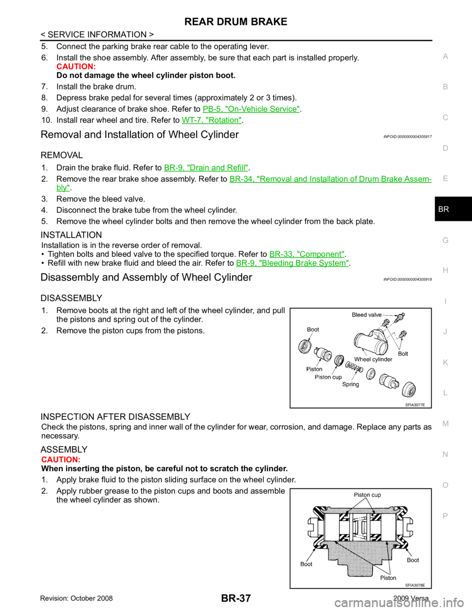
Disassembly and Assemb ly of Wheel Cylinder INFOID:0000000004305918
DISASSEMBLY 1. Remove boots at the right and left of the wheel cylinder, and pull the pistons and spring out of the cylinder.
2. Remove the piston cups from the pistons.
INSPECTION AFTER DISASSEMBLY Check the pistons, spring and inner wall of the cylinder for wear, corrosion, and damage. Replace any parts as
necessary.
ASSEMBLY CAUTION:
When inserting the piston, be caref ul not to scratch the cylinder.
1. Apply brake fluid to the piston sliding surface on the wheel cylinder.
2. Apply rubber grease to the piston cups and boots and assemble the wheel cylinder as shown.
Page 883 of 4331
CL
N
O P
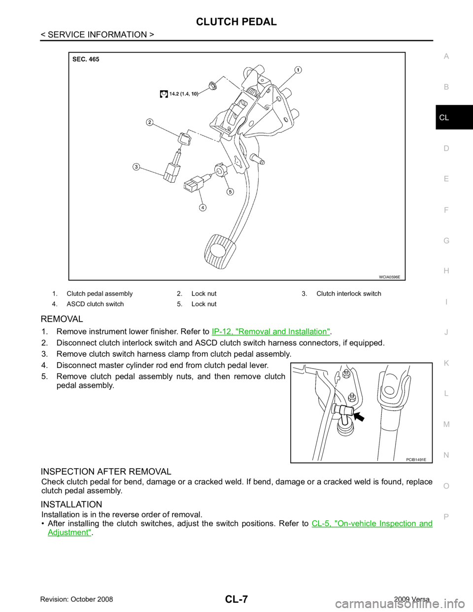
REMOVAL
1. Remove instrument lower finisher. Refer to IP-12, " Removal and Installation " .
2. Disconnect clutch interlock switch and ASCD clutch switch harness connectors, if equipped.
3. Remove clutch switch harness clamp from clutch pedal assembly.
4. Disconnect master cylinder rod end from clutch pedal lever.
5. Remove clutch pedal assembly nuts, and then remove clutch pedal assembly.
INSPECTION AFTER REMOVAL Check clutch pedal for bend, damage or a cracked weld. If bend, damage or a cracked weld is found, replace
clutch pedal assembly.
INSTALLATION Installation is in the reverse order of removal.
• After installing the clutch switches, adjust the switch positions. Refer to CL-5, " On-vehicle Inspection and
Adjustment " .
1. Clutch pedal assembly 2. Lock nut 3. Clutch interlock switch
4. ASCD clutch switch 5. Lock nut
Page 890 of 4331
.
2. Remove the air cleaner and air duct. Refer to EM-26, " Removal and Installation " (HR16DE models),
EM-139, " Removal and Installation " (MR18DE models).
3. Use one of the following methods to remove hose from clutch master cylinder. • Drain clutch fluid from reservoir tank and remove hose.
• Remove hose from clutch master cylinder. Immediat ely plug hose and reservoir tank to prevent clutch
fluid from dripping.
CAUTION:
Do not spill clutch fluid onto painted surfaces. If it spills, wi pe up immediately and wash the
affected area with water.
4. Remove clutch tube lock pin from clutch master cylinder.
5. Remove clutch tube lock pin at clutch housing.
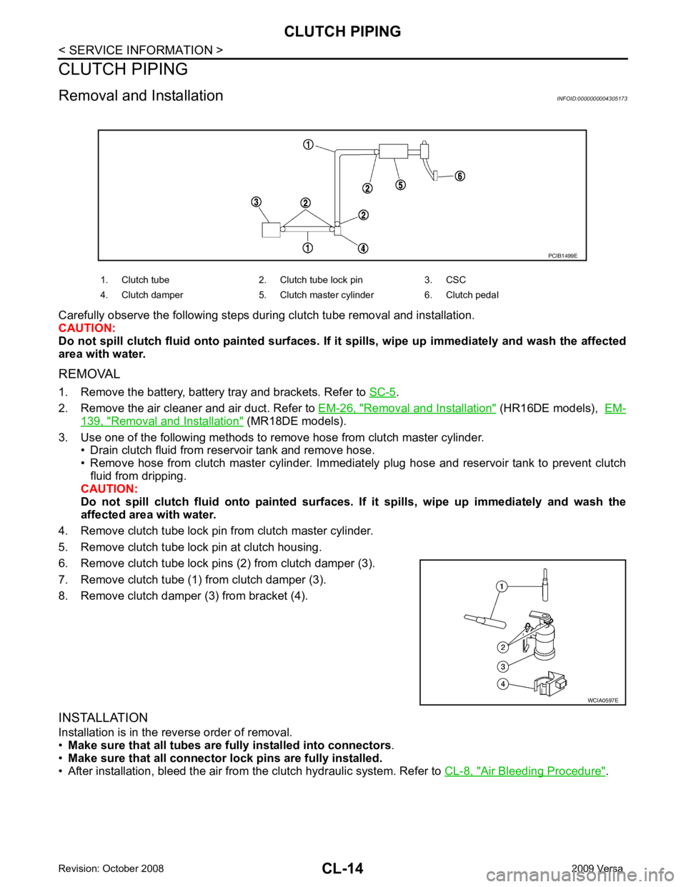
6. Remove clutch tube lock pins (2) from clutch damper (3).
7. Remove clutch tube (1) from clutch damper (3).
8. Remove clutch damper (3) from bracket (4).
INSTALLATION
Installation is in the reverse order of removal.
• Make sure that all tubes are fu lly installed into connectors.
• Make sure that all connector lock pins are fully installed.
• After installation, bleed the air from the clutch hydraulic system. Refer to CL-8, " Air Bleeding Procedure " .
1. Clutch tube 2. Clutch tube lock pin 3. CSC
4. Clutch damper 5. Clutch master cylinder 6. Clutch pedal WCIA0597E
Page 914 of 4331
Changing Engine Coolant " .
CAUTION:
• Perform this step when the engine is cold.
• Never spill engine coolant on drive belts.
2. Steer front wheel to the right.
3. Remove front fender protector (RH). Refer to EI-24, " Removal and Installation " .
4. Loosen mounting bolts of water pump pulley before loosening belt tension of drive belt.
5. Remove drive belt. Refer to EM-15, " Removal and Installation " .
6. Remove water pump pulley.
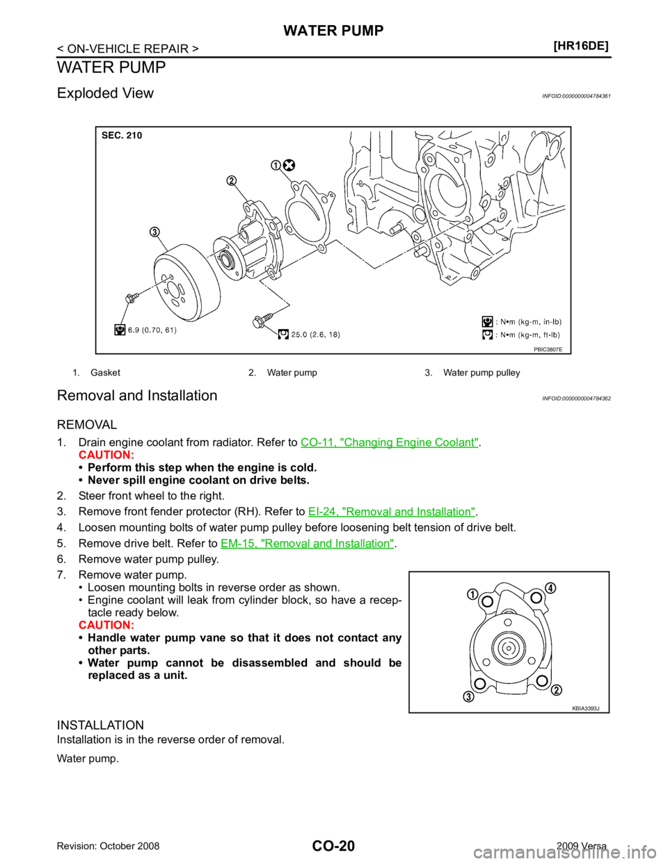
7. Remove water pump. • Loosen mounting bolts in reverse order as shown.
• Engine coolant will leak from cylinder block, so have a recep-
tacle ready below.
CAUTION:
• Handle water pump vane so that it does not contact any
other parts.
• Water pump cannot be disassembled and should be replaced as a unit.
INSTALLATION
Installation is in the reverse order of removal.
Water pump. 1. Gasket 2. Water pump 3. Water pump pulley
KBIA3393J
Page 916 of 4331
Changing Engine Coolant " .
CAUTION:
• Perform this step when engine is cold.
• Never spill engine coolant on drive belt.
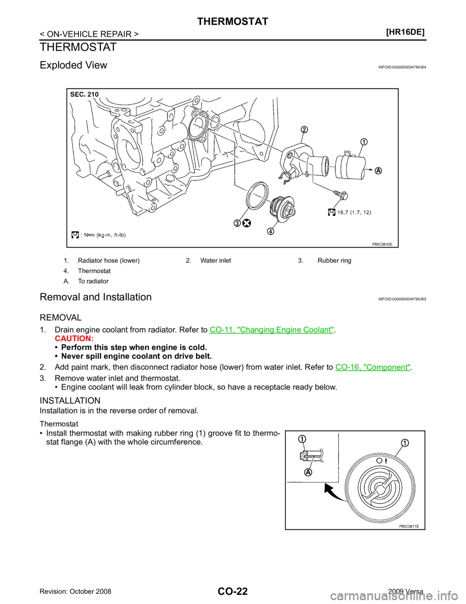
2. Add paint mark, then disconnect radiator hose (lower) from water inlet. Refer to CO-16, " Component " .
3. Remove water inlet and thermostat. • Engine coolant will leak from cylinder block, so have a receptacle ready below.
INSTALLATION
Installation is in the reverse order of removal.
Thermostat
• Install thermostat with making rubber ring (1) groove fit to thermo- stat flange (A) with the whole circumference. 1. Radiator hose (lower) 2. Water inlet 3. Rubber ring
4. Thermostat
A. To radiator PBIC3811E