2009 NISSAN TIIDA R1 0132
[x] Cancel search: R1 0132Page 1359 of 4331

EC
A
N
O P
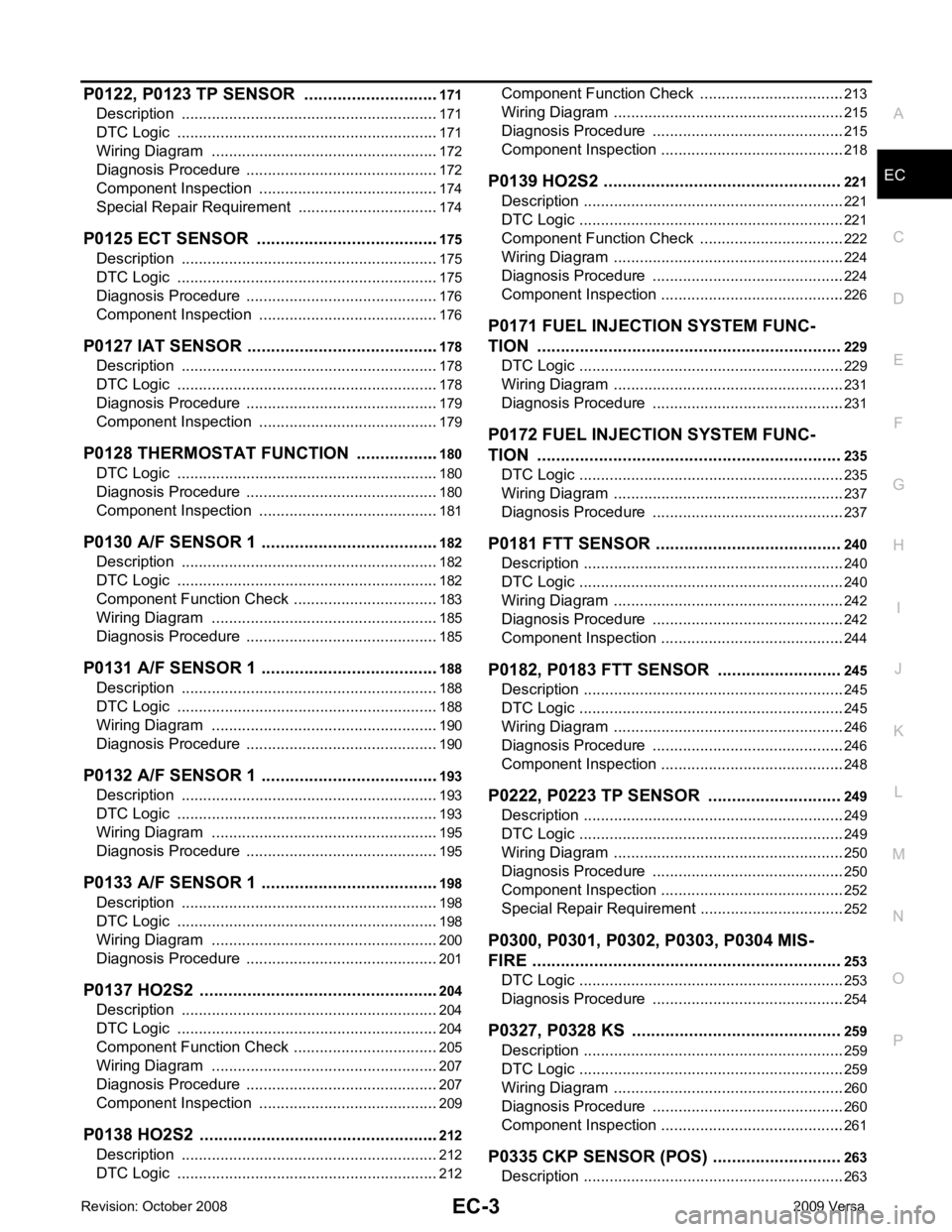
P0122, P0123 TP SENSOR ...........................
..171
Description .......................................................... ..171
DTC Logic ........................................................... ..171
Wiring Diagram ................................................... ..172
Diagnosis Procedure ........................................... ..172
Component Inspection ........................................ ..174
Special Repair Requirem ent .................................174
P0125 ECT SENSOR ..................................... ..175
Description .......................................................... ..175
DTC Logic ........................................................... ..175
Diagnosis Procedure ........................................... ..176
Component Inspection ........................................ ..176
P0127 IAT SENSOR ....................................... ..178
Description .......................................................... ..178
DTC Logic ........................................................... ..178
Diagnosis Procedure ........................................... ..179
Component Inspection ........................................ ..179
P0128 THERMOSTAT FUNCTION ................ ..180
DTC Logic ........................................................... ..180
Diagnosis Procedure ........................................... ..180
Component Inspection ........................................ ..181
P0130 A/F SENSOR 1 .................................... ..182
Description .......................................................... ..182
DTC Logic ........................................................... ..182
Component Function Check ................................ ..183
Wiring Diagram ................................................... ..185
Diagnosis Procedure ........................................... ..185
P0131 A/F SENSOR 1 .................................... ..188
Description .......................................................... ..188
DTC Logic ........................................................... ..188
Wiring Diagram ................................................... ..190
Diagnosis Procedure ........................................... ..190
P0132 A/F SENSOR 1 .................................... ..193
Description .......................................................... ..193
DTC Logic ........................................................... ..193
Wiring Diagram ................................................... ..195
Diagnosis Procedure ........................................... ..195
P0133 A/F SENSOR 1 .................................... ..198
Description .......................................................... ..198
DTC Logic ........................................................... ..198
Wiring Diagram ................................................... ..200
Diagnosis Procedure ........................................... ..201
P0137 HO2S2 ................................................. ..204
Description .......................................................... ..204
DTC Logic ........................................................... ..204
Component Function Check ................................ ..205
Wiring Diagram ................................................... ..207
Diagnosis Procedure ........................................... ..207
Component Inspection ........................................ ..209
P0138 HO2S2 ................................................. ..212
Description .......................................................... ..212
DTC Logic ........................................................... ..212 Component Function Check ................................
..213
Wiring Diagram .................................................... ..215
Diagnosis Procedure ........................................... ..215
Component Inspection ......................................... ..218
P0139 HO2S2 .................................................. 221
Description ........................................................... ..221
DTC Logic ............................................................ ..221
Component Function Check ................................ ..222
Wiring Diagram .................................................... ..224
Diagnosis Procedure ........................................... ..224
Component Inspection ......................................... ..226
P0171 FUEL INJECTION SYSTEM FUNC-
TION ................................................................ 229
DTC Logic ............................................................ ..229
Wiring Diagram .................................................... ..231
Diagnosis Procedure ........................................... ..231
P0172 FUEL INJECTION SYSTEM FUNC-
TION ................................................................ 235
DTC Logic ............................................................ ..235
Wiring Diagram .................................................... ..237
Diagnosis Procedure ........................................... ..237
P0181 FTT SENSOR ....................................... 240
Description ........................................................... ..240
DTC Logic ............................................................ ..240
Wiring Diagram .................................................... ..242
Diagnosis Procedure ........................................... ..242
Component Inspection ......................................... ..244
P0182, P0183 FTT SENSOR .......................... 245
Description ........................................................... ..245
DTC Logic ............................................................ ..245
Wiring Diagram .................................................... ..246
Diagnosis Procedure ........................................... ..246
Component Inspection ......................................... ..248
P0222, P0223 TP SENSOR ............................ 249
Description ........................................................... ..249
DTC Logic ............................................................ ..249
Wiring Diagram .................................................... ..250
Diagnosis Procedure ........................................... ..250
Component Inspection ......................................... ..252
Special Repair Requiremen t ..................................252
P0300, P0301, P0302, P0303, P0304 MIS-
FIRE ................................................................. 253
DTC Logic ............................................................ ..253
Diagnosis Procedure ........................................... ..254
P0327, P0328 KS ............................................ 259
Description ........................................................... ..259
DTC Logic ............................................................ ..259
Wiring Diagram .................................................... ..260
Diagnosis Procedure ........................................... ..260
Component Inspection ......................................... ..261
P0335 CKP SENSOR (POS) ........................... 263
Description ........................................................... ..263
Page 1365 of 4331

EC
A
N
O P
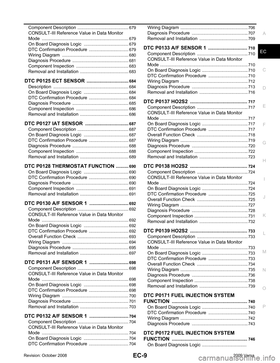
Component Description .......................................
..
679
CONSULT-III Refe rence Value in Data Monitor
Mode ................................................................... ..
679
On Board Diagnosis Logic .................................. ..679
DTC Confirmation Procedure .............................. ..679
Wiring Diagram ................................................... ..680
Diagnosis Procedure ........................................... ..681
Component Inspection ........................................ ..683
Removal and Installation .......................................683
DTC P0125 ECT SENSOR ............................. ..684
Description .......................................................... ..684
On Board Diagnosis Logic .................................. ..684
DTC Confirmation Procedure .............................. ..684
Diagnosis Procedure ........................................... ..685
Component Inspection ........................................ ..686
Removal and Installation .......................................686
DTC P0127 IAT SENSOR .............................. ..687
Component Description ....................................... ..687
On Board Diagnosis Logic .................................. ..687
DTC Confirmation Procedure .............................. ..687
Diagnosis Procedure ........................................... ..688
Component Inspection ........................................ ..688
Removal and Installation .......................................689
DTC P0128 THERMOSTAT FUNCTION ........ ..690
On Board Diagnosis Logic .................................. ..690
DTC Confirmation Procedure .............................. ..690
Diagnosis Procedure ........................................... ..690
Component Inspection ........................................ ..691
Removal and Installation .......................................691
DTC P0130 A/F SENSOR 1 ........................... ..692
Component Description ....................................... ..692
CONSULT-III Refe rence Value in Data Monitor
Mode ................................................................... ..
692
On Board Diagnosis Logic .................................. ..692
DTC Confirmation Procedure .............................. ..692
Overall Function Check ....................................... ..693
Wiring Diagram ................................................... ..694
Diagnosis Procedure ........................................... ..695
Removal and Installation .......................................697
DTC P0131 A/F SENSOR 1 ........................... ..698
Component Description ....................................... ..698
CONSULT-III Refe rence Value in Data Monitor
Mode ................................................................... ..
698
On Board Diagnosis Logic .................................. ..698
DTC Confirmation Procedure .............................. ..698
Wiring Diagram ................................................... ..700
Diagnosis Procedure ........................................... ..701
Removal and Installation .......................................703
DTC P0132 A/F SENSOR 1 ........................... ..704
Component Description ....................................... ..704
CONSULT-III Refe rence Value in Data Monitor
Mode ................................................................... ..
704
On Board Diagnosis Logic .................................. ..704
DTC Confirmation Procedure .............................. ..704 Wiring Diagram ....................................................
..706
Diagnosis Procedure ........................................... ..707
Removal and Installation ..................................... ..709
DTC P0133 A/F SENSOR 1 ............................ 710
Component Description ....................................... ..710
CONSULT-III Reference Va lue in Data Monitor
Mode .................................................................... ..
710
On Board Diagnosis Logic ................................... ..710
DTC Confirmation Procedure .............................. ..710
Wiring Diagram .................................................... ..712
Diagnosis Procedure ........................................... ..713
Removal and Installation ..................................... ..716
DTC P0137 HO2S2 ......................................... 717
Component Description ....................................... ..717
CONSULT-III Reference Va lue in Data Monitor
Mode .................................................................... ..
717
On Board Diagnosis Logic ................................... ..717
DTC Confirmation Procedure .............................. ..717
Overall Function Check ....................................... ..718
Wiring Diagram .................................................... ..719
Diagnosis Procedure ........................................... ..720
Component Inspection ......................................... ..722
Removal and Installation ..................................... ..723
DTC P0138 HO2S2 ......................................... 724
Component Description ....................................... ..724
CONSULT-III Reference Va lue in Data Monitor
Mode .................................................................... ..
724
On Board Diagnosis Logic ................................... ..724
DTC Confirmation Procedure .............................. ..725
Overall Function Check ....................................... ..725
Wiring Diagram .................................................... ..727
Diagnosis Procedure ........................................... ..728
Component Inspection ......................................... ..731
Removal and Installation ..................................... ..732
DTC P0139 HO2S2 ......................................... 733
Component Description ....................................... ..733
CONSULT-III Reference Va lue in Data Monitor
Mode .................................................................... ..
733
On Board Diagnosis Logic ................................... ..733
DTC Confirmation Procedure .............................. ..733
Overall Function Check ....................................... ..734
Wiring Diagram .................................................... ..735
Diagnosis Procedure ........................................... ..736
Component Inspection ......................................... ..738
Removal and Installation ..................................... ..739
DTC P0171 FUEL INJECTION SYSTEM
FUNCTION ....... ...............................................
740
On Board Diagnosis Logic ................................... ..740
DTC Confirmation Procedure .............................. ..740
Wiring Diagram .................................................... ..742
Diagnosis Procedure ........................................... ..743
DTC P0172 FUEL INJECTION SYSTEM
FUNCTION ....... ............................................... 746
On Board Diagnosis Logic ...................................
Page 1472 of 4331

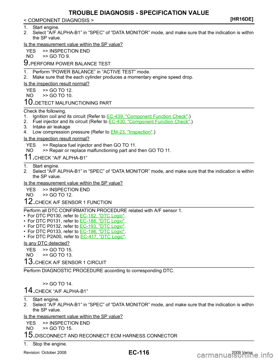
YES >> INSPECTION END
NO >> GO TO 9. YES >> GO TO 12.
NO >> GO TO 10. Component Function Check " .)
2. Fuel injector and its circuit (Refer to EC-430, " Component Function Check " .)
3. Intake air leakage
4. Low compression pressure (Refer to EM-23, " Inspection " .)
Is the inspection result normal? YES >> Replace fuel injector and then GO TO 11.
NO >> Repair or replace malfunctioning part and then GO TO 11. YES >> INSPECTION END
NO >> GO TO 12. DTC Logic " .
• For DTC P0131, refer to EC-188, " DTC Logic " .
• For DTC P0132, refer to EC-193, " DTC Logic " .
• For DTC P0133, refer to EC-198, " DTC Logic " .
• For DTC P2A00, refer to EC-417, " DTC Logic " .
Is any DTC detected? YES >> GO TO 15.
NO >> GO TO 13. YES >> INSPECTION END
NO >> GO TO 15.
Page 1549 of 4331
![NISSAN TIIDA 2009 Service Repair Manual P0132 A/F SENSOR 1
EC-193
< COMPONENT DIAGNOSIS >
[HR16DE] C
D E
F
G H
I
J
K L
M A EC
NP
O
P0132 A/F SENSOR 1
Description INFOID:0000000004780114
The air fuel ratio (A/F) sensor 1 is a planar one-cell NISSAN TIIDA 2009 Service Repair Manual P0132 A/F SENSOR 1
EC-193
< COMPONENT DIAGNOSIS >
[HR16DE] C
D E
F
G H
I
J
K L
M A EC
NP
O
P0132 A/F SENSOR 1
Description INFOID:0000000004780114
The air fuel ratio (A/F) sensor 1 is a planar one-cell](/manual-img/5/57398/w960_57398-1548.png)
P0132 A/F SENSOR 1
EC-193
< COMPONENT DIAGNOSIS >
[HR16DE] C
D E
F
G H
I
J
K L
M A EC
NP
O
P0132 A/F SENSOR 1
Description INFOID:0000000004780114
The air fuel ratio (A/F) sensor 1 is a planar one-cell limit current sen-
sor. The sensor element of the A/F sensor 1 is composed an elec-
trode layer, which transports ions. It has a heater in the element.
The sensor is capable of precise m easurement = 1, but also in the
lean and rich range. Together with its control electronics, the sensor
outputs a clear, continuous signal throughout a wide range.
The exhaust gas components diffuse through the diffusion layer at
the sensor cell. An electrode layer is applied voltage, and this current
relative oxygen density in lean. Also this current relative hydrocar-
bon density in rich.
Therefore, the A/F sensor 1 is able to indicate air fuel ratio by this
electrode layer of current. In addition, a heater is integrated in the
sensor to ensure the required operating temperature of about 800 °C
(1,472 °F).
DTC Logic INFOID:0000000004780115
DTC DETECTION LOGIC To judge the malfunction, the diagnosis checks that the A/F signal computed by ECM from the A/F sensor 1
signal is not inordinately high.
DTC CONFIRMATION PROCEDURE 1.
PRECONDITIONING
If DTC Confirmation Procedure has been previously conduc ted, always turn ignition switch OFF and wait at
least 10 seconds before conducting the next test.
TESTING CONDITION:
Before performing the following procedure, confirm that battery voltage is more than 10.5 V at idle.
>> GO TO 2. 2.
CHECK A/F SENSOR FUNCTION
With CONSULT-III
1. Start engine and warm it up to normal operating temperature.
2. Select “A/F SEN1 (B1)” in “DAT A MONITOR” mode with CONSULT-III.
3. Check “A/F SEN1 (B1)” indication.
With GST
Follow the procedure “With CONSULT-IIII” above.
Is the indication constantly approx. 5 V? JMBIA0112GB
PBIB3354E
DTC No. Trouble diagnosis name DTC detecting condition Possible Cause
P0132 Air fuel ratio (A/F) sensor 1
circuit high voltage • The A/F signal computed by ECM from the A/F
sensor 1 signal is constantly approx. 5 V. • Harness or connectors
(The A/F sensor 1 circuit is open or
shorted.)
• A/F sensor 1
Page 1551 of 4331
![NISSAN TIIDA 2009 Service Repair Manual P0132 A/F SENSOR 1
EC-195
< COMPONENT DIAGNOSIS >
[HR16DE] C
D E
F
G H
I
J
K L
M A EC
NP
O
Wiring Diagram
INFOID:0000000004780711
Diagnosis Procedure INFOID:00000000047801161.
CHECK GROUND CONNECTION
NISSAN TIIDA 2009 Service Repair Manual P0132 A/F SENSOR 1
EC-195
< COMPONENT DIAGNOSIS >
[HR16DE] C
D E
F
G H
I
J
K L
M A EC
NP
O
Wiring Diagram
INFOID:0000000004780711
Diagnosis Procedure INFOID:00000000047801161.
CHECK GROUND CONNECTION](/manual-img/5/57398/w960_57398-1550.png)
P0132 A/F SENSOR 1
EC-195
< COMPONENT DIAGNOSIS >
[HR16DE] C
D E
F
G H
I
J
K L
M A EC
NP
O
Wiring Diagram
INFOID:0000000004780711
Diagnosis Procedure INFOID:00000000047801161.
CHECK GROUND CONNECTION
1. Turn ignition switch OFF.
2. Check ground connections E15, E24. Refer to EC-125, " Ground Inspection " .
Is the inspection result normal? AABWA0307G B
Page 1552 of 4331
![NISSAN TIIDA 2009 Service Repair Manual EC-196< COMPONENT DIAGNOSIS >
[HR16DE]
P0132 A/F SENSOR 1
YES >> GO TO 2.
NO >> Repair or replace ground connection. 2.
CHECK AIR FUEL RATIO (A/F) SENSOR 1 POWER SUPPLY CIRCUIT
1. Disconnect A/F senso NISSAN TIIDA 2009 Service Repair Manual EC-196< COMPONENT DIAGNOSIS >
[HR16DE]
P0132 A/F SENSOR 1
YES >> GO TO 2.
NO >> Repair or replace ground connection. 2.
CHECK AIR FUEL RATIO (A/F) SENSOR 1 POWER SUPPLY CIRCUIT
1. Disconnect A/F senso](/manual-img/5/57398/w960_57398-1551.png)
EC-196< COMPONENT DIAGNOSIS >
[HR16DE]
P0132 A/F SENSOR 1
YES >> GO TO 2.
NO >> Repair or replace ground connection. 2.
CHECK AIR FUEL RATIO (A/F) SENSOR 1 POWER SUPPLY CIRCUIT
1. Disconnect A/F sensor 1 harness connector.
2. Turn ignition switch ON.
3. Check the voltage between A/F sensor 1 harness connector and
ground.
Is the inspection result normal? YES >> GO TO 4.
NO >> GO TO 3. 3.
DETECT MALFUNCTIONING PART
Check the following.
• Harness connectors E8, F8
• IPDM E/R harness connector E45
• 10 A fuse (No. 54)
• Harness for open or short between A/F sensor 1 and fuse
>> Repair or replace harness or connectors. 4.
CHECK A/F SENSOR 1 INPUT SIGN AL CIRCUIT FOR OPEN AND SHORT
1. Turn ignition switch OFF.
2. Disconnect ECM harness connector.
3. Check the continuity between A/F sensor 1 harness connector and ECM harness connector.
4. Check the continuity between A/F sensor 1 harness connector and ground, or ECM harness connector
and ground.
5. Also check harness for short to power.
Is the inspection result normal? YES >> GO TO 5.
NO >> Repair open circuit or short to ground or short to power in harness or connectors. 5.
CHECK INTERMITTENT INCIDENT A/F sensor 1
Ground Voltage
Connector Terminal
F12 4 Ground Battery voltage PBIB3308E
A/F sensor 1 ECM
Continuity
Connector Terminal Connector Terminal
F12 1
F11 49
Existed
2 53
A/F sensor 1 Ground Continuity
Connector Terminal
F12 1
Ground Not existed
2
ECM Ground Continuity
Connector Terminal
F11 49
Ground Not existed
53
Page 1578 of 4331
![NISSAN TIIDA 2009 Service Repair Manual EC-222< COMPONENT DIAGNOSIS >
[HR16DE]
P0139 HO2S2
3. Start engine and keep the engine speed between 3,500 and 4,000 rpm for at least 1 minute under no load.
4. Let engine idle for 1 minute.
5. Open NISSAN TIIDA 2009 Service Repair Manual EC-222< COMPONENT DIAGNOSIS >
[HR16DE]
P0139 HO2S2
3. Start engine and keep the engine speed between 3,500 and 4,000 rpm for at least 1 minute under no load.
4. Let engine idle for 1 minute.
5. Open](/manual-img/5/57398/w960_57398-1577.png)
EC-222< COMPONENT DIAGNOSIS >
[HR16DE]
P0139 HO2S2
3. Start engine and keep the engine speed between 3,500 and 4,000 rpm for at least 1 minute under no load.
4. Let engine idle for 1 minute.
5. Open engine hood.
6. Select “HO2S2 (B1) P0139” of “HO2S2” in “DTC WORK SUPPORT” mode with CONSULT-III.
7. Follow the instruction of CONSULT-III. NOTE:
It will take at most 10 minutes until “COMPLETED” is displayed.
8. Touch “SELF-DIAG RESULT”.
Which is displayed on CONSULT-III? OK >> INSPECTION END
NG >> GO TO 4.
CAN NOT BE DIAGNOSED>>GO TO 4. 4.
PERFORM THE RESULT OF DTC CONFIRMATION PROCEDURE
1. Turn ignition switch OFF and leave the vehi cle in a cool place (soak the vehicle).
2. Perform DTC CONFIRMATION PROCEDURE again.
>> GO TO 3. 5.
PERFORM COMPONENT FUNCTION CHECK
Perform component function check. Refer to EC-222, " Component Function Check " .
NOTE:
Use component function check to check the overall func tion of the heated oxygen sensor 2 circuit. During this
check, a 1st trip DTC might not be confirmed.
Is the inspection result normal? YES >> INSPECTION END
NO >> Go to EC-224, " Diagnosis Procedure " .
Component Function Check INFOID:00000000047801321.
PERFORM COMPONENT FUNCTION CHECK-I
Without CONSULT-III
1. Start engine and warm it up to normal operating temperature.
2. Turn ignition switch OFF and wait at least 10 seconds.
3. Start engine and keep the engine speed between 3,500 and 4,000 rpm for at least 1 minute under no load.
4. Let engine idle for 1 minute.
5. Check the voltage between ECM harness connector and ground under the following condition.
Is the inspection result normal? YES >> INSPECTION END
NO >> GO TO 2. 2.
PERFORM COMPONENT FUNCTION CHECK-IIECM
Ground Condition Voltage
Con-
nector Terminal
F11 50
(HO2S2
signal) Ground
Revving up to 4,000
rpm under no load at
least 10 times The voltage should be above
0.30 V at least once during
this procedure. PBIB2996E
Page 1831 of 4331

EC
NP
O
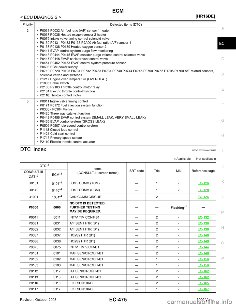
DTC Index
INFOID:0000000004780387
× :Applicable —: Not applicable
2 • P0031 P0032 Air fuel ratio (A/F) sensor 1 heater
• P0037 P0038 Heated oxygen sensor 2 heater
• P0075 Intake valve timing control solenoid valve
• P0130 P0131 P0132 P0133 P2A00 Air fuel ratio (A/F) sensor 1
• P0137 P0138 P0139 Heated oxygen sensor 2
• P0441 EVAP control system purge flow monitoring
• P0443 P0444 P0445 EVAP canister purge volume control solenoid valve
• P0447 P0448 EVAP canister vent control valve
• P0451 P0452 P0453 EVAP control system pressure sensor
• P0603 ECM power supply
• P0710 P0720 P0725 P0731 P0732 P0733 P0734 P0740 P0744 P0745 P0750 P0755 P1705 P1760 A/T related sensors,
solenoid valves and switches
• P1217 Engine over temperature (OVERHEAT)
• P1805 Brake switch
• P2100 P2103 Throttle control motor relay
• P2101 Electric throttle control function
• P2118 Throttle control motor
3 • P0011 Intake valve timing control • P0171 P0172 Fuel injection system function
• P0300 - P0304 Misfire
• P0420 Three way catalyst function
• P0442 P0456 EVAP control system (SMALL LEAK, VERY SMALL LEAK)
• P0455 EVAP control system (GROSS LEAK)
• P0506 P0507 Idle speed control system
• P1148 Closed loop control
• P1421 Cold start control
• P1715 Primary speed sensor
• P2119 Electric throttle control actuator
Priority Detected items (DTC) DTC*
1
Items
(CONSULT-III screen terms) SRT code Trip MIL Reference page
CONSULT-III
GST* 2
ECM*3
U0101 0101*4
LOST COMM (TCM) — 1 ×EC-126 U0140
0140*4
LOST COMM (BCM) — 1 ×EC-128 U1001
1001*4
CAN COMM CIRCUIT — 2 — EC-126P0031 0031 A/F SEN1 HTR (B1) — 2
×EC-136 P0032 0032 A/F SEN1 HTR (B1) — 2
×EC-136 P0037 0037 HO2S2 HTR (B1) — 2
×EC-140 P0038 0038 HO2S2 HTR (B1) — 2
×EC-140 P0075 0075 INT/V TIM V/CIR-B1 — 2
×EC-144 P0101 0101 MAF SEN/CIRCUIT-B1 — 2
×EC-148 P0102 0102 MAF SEN/CIRCUIT-B1 — 1
×EC-156 P0103 0103 MAF SEN/CIRCUIT-B1 — 1
×EC-156 P0112 0112 IAT SEN/CIRCUIT-B1 — 2
×EC-162 P0113 0113 IAT SEN/CIRCUIT-B1 — 2
×EC-162 P0116 0116 ECT SEN/CIRC — 2
×EC-165 P0117 0117 ECT SEN/CIRC — 1
×EC-167