2009 NISSAN TIIDA oil filter tool
[x] Cancel search: oil filter toolPage 2948 of 4331
EM
N
O P
CONTENTS
ENGINE MECHANICAL
HR16DE
PRECAUTION ....... ........................................
4
PRECAUTIONS .............................................. .....4
Precaution for Supplemental Restraint System
(SRS) "AIR BAG" and "SEAT BELT PRE-TEN-
SIONER" ............................................................. ......
4
Precaution Necessary fo r Steering Wheel Rota-
tion After Battery Disconnect ............................... ......
4
Precaution for Procedure without Cowl Top Cover ......5
Precaution for Drain Cool ant .....................................5
Precaution for Disconnecting Fuel Piping ........... ......5
Precaution for Removal and Disassembly ................5
Precaution for Inspection, Repair and Replace-
ment .................................................................... ......
5
Precaution for Assembly and Installation ..................5
Parts Requiring Angular Tightening ..........................6
Precaution for Liquid Gasket ............................... ......6
PREPARATION .... ........................................8
PREPARATION .............................................. .....8
Special Service Tools .......................................... ......8
Commercial Service Tools .................................. ......9
SYMPTOM DIAGNOSIS ..... .........................12
NOISE, VIBRATION AND HARSHNESS
(NVH) TROUBLESHOOTING ........................ ....
12
NVH Troubleshooting - Engine Noise ................. ....12
Use the Chart Below to Help You Find the Cause
of the Symptom ................................................... ....
13
ON-VEHICLE MAINTENA NCE ....................14
DRIVE BELTS ................................................ ....14
Checking ............................................................. ....14
Tension Adjustment ............................................ ....14
Removal and Installation .........................................15
AIR CLEANER FILTER .................................. ....17 Removal and Installation .....................................
....17
SPARK PLUG ................................................... 18
Exploded View ..................................................... ....18
Removal and Installation ..................................... ....18
CAMSHAFT VALVE CLEARANCE .................. 20
Inspection and Adjustment .................................. ....20
COMPRESSION PRESSURE ........................... 23
Inspection ............................................................ ....23
ON-VEHICLE REPAIR ..... ............................24
DRIVE BELT IDLER PULLEY .......................... 24
Exploded View ..................................................... ....24
Removal and Installation ..................................... ....24
AIR CLEANER AND AIR DUCT ....................... 26
Exploded View ..................................................... ....26
Removal and Installation ..................................... ....26
Inspection ............................................................ ....27
INTAKE MANIFOLD ......................................... 28
Exploded View ..................................................... ....28
Removal and Installation ..................................... ....28
EXHAUST MANIFOLD ...................................... 31
Exploded View ..................................................... ....31
Removal and Installation ..................................... ....31
FUEL INJECTOR AND FUEL TUBE ................ 34
Exploded View ..................................................... ....34
Removal and Installation ..................................... ....34
Inspection ............................................................ ....38
OIL PAN (LOWER) ........................................... 39
Exploded View ..................................................... ....39
Removal and Installation ..................................... ....39
Inspection ............................................................ ....41
OIL PAN (UPPER) AND OIL STRAINER ......... 42
Component .......................................................... ....42
Page 3017 of 4331
![NISSAN TIIDA 2009 Service Repair Manual EM-70< ON-VEHICLE REPAIR >
[HR16DE]
CAMSHAFT
c. Tighten bolts in the numerical order shown.
d. After all bolts are tightened, retighten them to specified torque in numerical order as shown.
CAUTION:
B NISSAN TIIDA 2009 Service Repair Manual EM-70< ON-VEHICLE REPAIR >
[HR16DE]
CAMSHAFT
c. Tighten bolts in the numerical order shown.
d. After all bolts are tightened, retighten them to specified torque in numerical order as shown.
CAUTION:
B](/manual-img/5/57398/w960_57398-3016.png)
EM-70< ON-VEHICLE REPAIR >
[HR16DE]
CAMSHAFT
c. Tighten bolts in the numerical order shown.
d. After all bolts are tightened, retighten them to specified torque in numerical order as shown.
CAUTION:
Be sure to wipe off any excessive liquid gasket leaking to
surface.
22. Insert crankshaft pulley by aligning with crankshaft key. • When inserting crankshaft pulley with a plastic hamme r, tap on its center portion (not circumference).
CAUTION:
Never damage front oil seal lip section.
23. Tighten crankshaft pulley bolt with the following procedure: • Secure crankshaft pulley with a suitable tool, and tighten crankshaft pulley bolt.
a. Apply new engine oil to thread and seat surfaces of crankshaft pulley bolt.
b. Tighten crankshaft pulley bolt.
c. Put a paint mark (B) on crankshaft pulley, mating with any one of six easy to recognize angle marks (A) on crankshaft bolt flange
(1).
d. Turn another 60 degrees clockwise (angle tightening). • Check the tightening angle with movement of one angle mark.
24. Make sure that crankshaft turns smoothly by rotating by hand clockwise.
25. Install the camshaft position sensor (PHASE) to the rear end of cylinder head.
• Tighten bolts with it seated completely.
26. Check and adjust valve clearance. Refer to EM-20, " Inspection and Adjustment " .
27. Installation of the remaining components is in the reverse order of removal.
Inspection INFOID:0000000004784301
INSPECTION AFTER REMOVAL
Oil Filter KBIA3429J
Crankshaft pulley bolt : 35.0 N·m (3.6 kg-m, 26 ft-lb)
PBIC3726E
Page 3078 of 4331
![NISSAN TIIDA 2009 Service Repair Manual PREPARATION
EM-131
< SERVICE INFORMATION >
[MR18DE] C
D E
F
G H
I
J
K L
M A EM
NP
O
ST16610001
(J-23907)
Pilot bushing puller Removing crankshaft pilot bushing
KV11103000
( — )
Pulley puller Rem NISSAN TIIDA 2009 Service Repair Manual PREPARATION
EM-131
< SERVICE INFORMATION >
[MR18DE] C
D E
F
G H
I
J
K L
M A EM
NP
O
ST16610001
(J-23907)
Pilot bushing puller Removing crankshaft pilot bushing
KV11103000
( — )
Pulley puller Rem](/manual-img/5/57398/w960_57398-3077.png)
PREPARATION
EM-131
< SERVICE INFORMATION >
[MR18DE] C
D E
F
G H
I
J
K L
M A EM
NP
O
ST16610001
(J-23907)
Pilot bushing puller Removing crankshaft pilot bushing
KV11103000
( — )
Pulley puller Removing crankshaft pulley
KV991J0050
(J-44626)
Air fuel sensor Socket Loosening or tightening air fuel ratio sen-
sor
a: 22 mm (0.87 in)
KV10114400
(J-38365)
Heated oxygen sensor wrench Loosening or tightening rear heated oxy-
gen sensor
a: 22 mm (0.87 in)
KV11105210
(J-44716)
Stopper plate Securing drive plate and flywheel
KV10115600
(J-38958)
Valve oil seal drift Installing valve oil seal
Use side A.
a: 20 (0.79) dia .
b: 13 (0.51) dia.
c: 10.3 (0.406) dia .
d: 8 (0.31) dia.
e: 10.7 (0.421)
f: 5 (0.20)
KV10115801
( — )
Oil filter wrench Removing and installing oil filter
a: 64.3 mm (2.531 in)
Tool number
(Kent-Moore No.)
Tool name DescriptionNT045
NT676
LBIA0444E
NT636
ZZA0009D
S-NT603
S-NT375
Page 3095 of 4331
![NISSAN TIIDA 2009 Service Repair Manual EM-148< SERVICE INFORMATION >
[MR18DE]
OIL PAN
3. Remove flywheel (M/T models) or drive plate (CVT or A/T models). Refer to EM-199, " Component " .
4. Remove oil filter using Tool.
CAUTION:
When remo NISSAN TIIDA 2009 Service Repair Manual EM-148< SERVICE INFORMATION >
[MR18DE]
OIL PAN
3. Remove flywheel (M/T models) or drive plate (CVT or A/T models). Refer to EM-199, " Component " .
4. Remove oil filter using Tool.
CAUTION:
When remo](/manual-img/5/57398/w960_57398-3094.png)
EM-148< SERVICE INFORMATION >
[MR18DE]
OIL PAN
3. Remove flywheel (M/T models) or drive plate (CVT or A/T models). Refer to EM-199, " Component " .
4. Remove oil filter using Tool.
CAUTION:
When removing, prepare a shop cloth to ab sorb any engine oil leakage or spillage.
5. Remove oil pan (lower) bolts in reverse order as shown.
6. After removing the bolts and nuts, separate the mating surface and remove the sealant using Tool.
• Slide (2) the Tool by tapping (1) its side with a hammer to remove the oil pan (lower) from the oil pan (upper).
CAUTION:
Be careful not to damage the mating surfaces.
7. Remove the following parts: • Front cover, timing chain, oil pump drive chain; Refer to EM-160 .
8. Remove oil pump. • Loosen bolts in reverse order as shown.
9. Remove oil pan (upper) bolts in reverse order as shown. Tool number : KV10115801 ( — )
: Engine front PBIC3146J
Tool number : KV10111100 (J-37228)
WBIA0566E
1 : Oil pump
2 : Oil pan (upper)
: Engine front PBIC3532J
: Engine front
PBIC3533J
Page 3096 of 4331
EM
NP
O
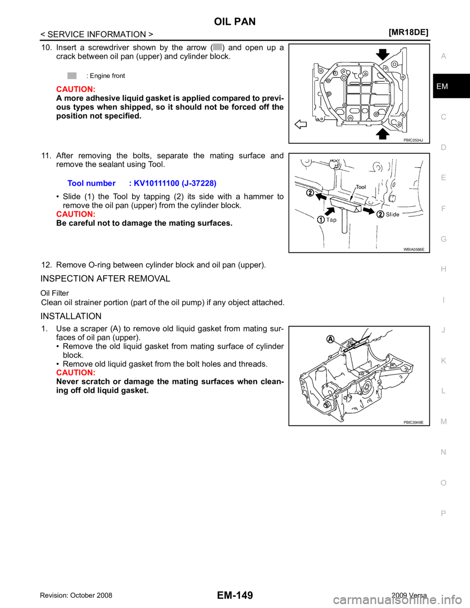
10. Insert a screwdriver shown by the arrow ( ) and open up a
crack between oil pan (upper) and cylinder block.
CAUTION:
A more adhesive liquid gasket is applied compared to previ-
ous types when shipped, so it should not be forced off the
position not specified.
11. After removing the bolts, separate the mating surface and remove the sealant using Tool.
• Slide (1) the Tool by tapping (2) its side with a hammer to remove the oil pan (upper) from the cylinder block.
CAUTION:
Be careful not to damage the mating surfaces.
12. Remove O-ring between cylinder block and oil pan (upper).
INSPECTION AFTER REMOVAL
Oil Filter Clean oil strainer portion (part of the oil pump) if any object attached.
INSTALLATION 1. Use a scraper (A) to remove old liquid gasket from mating sur- faces of oil pan (upper).
• Remove the old liquid gasket from mating surface of cylinder
block.
• Remove old liquid gasket from the bolt holes and threads.
CAUTION:
Never scratch or damage the mating surfaces when clean-
ing off old liquid gasket. : Engine front
Page 3099 of 4331
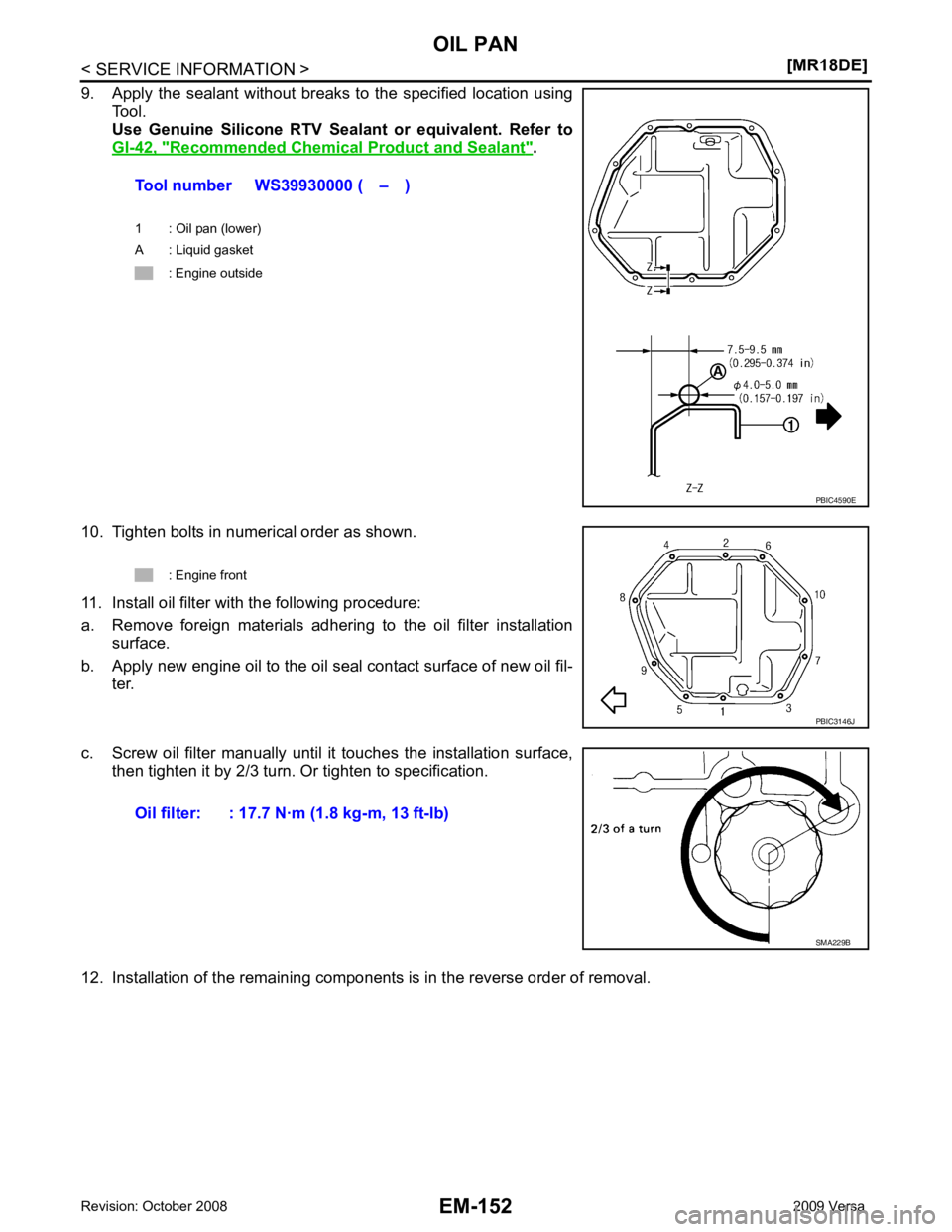
Recommended Chemical
Product and Sealant " .
10. Tighten bolts in numerical order as shown.
11. Install oil filter with the following procedure:
a. Remove foreign materials adhering to the oil filter installation surface.
b. Apply new engine oil to the oil seal contact surface of new oil fil- ter.
c. Screw oil filter manually until it touches the installation surface, then tighten it by 2/3 turn. Or tighten to specification.
12. Installation of the remaining components is in the reverse order of removal. Tool number WS39930000 ( – )
1 : Oil pan (lower)
A : Liquid gasket
: Engine outside
Page 3148 of 4331
EM
NP
O
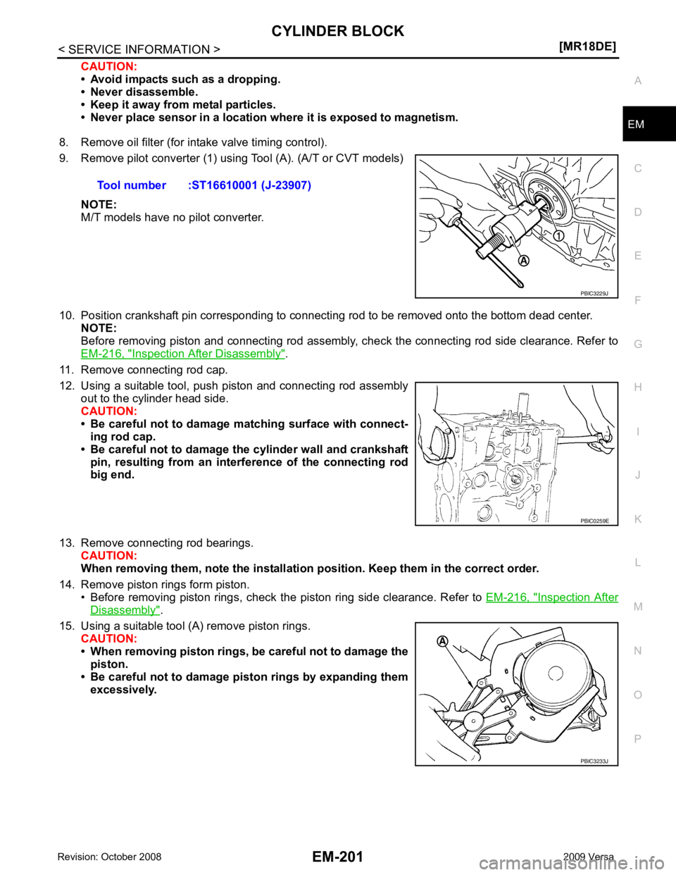
CAUTION:
• Avoid impacts such as a dropping.
• Never disassemble.
• Keep it away from metal particles.
• Never place sensor in a location wher e it is exposed to magnetism.
8. Remove oil filter (for intake valve timing control).
9. Remove pilot converter (1) using Tool (A). (A/T or CVT models)
NOTE:
M/T models have no pilot converter.
10. Position crankshaft pin corresponding to connecting rod to be removed onto the bottom dead center. NOTE:
Before removing piston and connecting rod assembly, check the connecting rod side clearance. Refer to
EM-216, " Inspection After Disassembly " .
11. Remove connecting rod cap.
12. Using a suitable tool, push piston and connecting rod assembly out to the cylinder head side.
CAUTION:
• Be careful not to damage matching surface with connect- ing rod cap.
• Be careful not to damage the cylinder wall and crankshaft pin, resulting from an inte rference of the connecting rod
big end.
13. Remove connecting rod bearings. CAUTION:
When removing them, note the installation position. Keep them in the correct order.
14. Remove piston rings form piston. • Before removing piston rings, check the piston ring side clearance. Refer to EM-216, " Inspection After
Disassembly " .
15. Using a suitable tool (A) remove piston rings. CAUTION:
• When removing piston rings, be careful not to damage the
piston.
• Be careful not to damage piston rings by expanding them excessively.Tool number :ST16610001 (J-23907)
PBIC0259E
PBIC3233J
Page 3722 of 4331
LU
N
O P
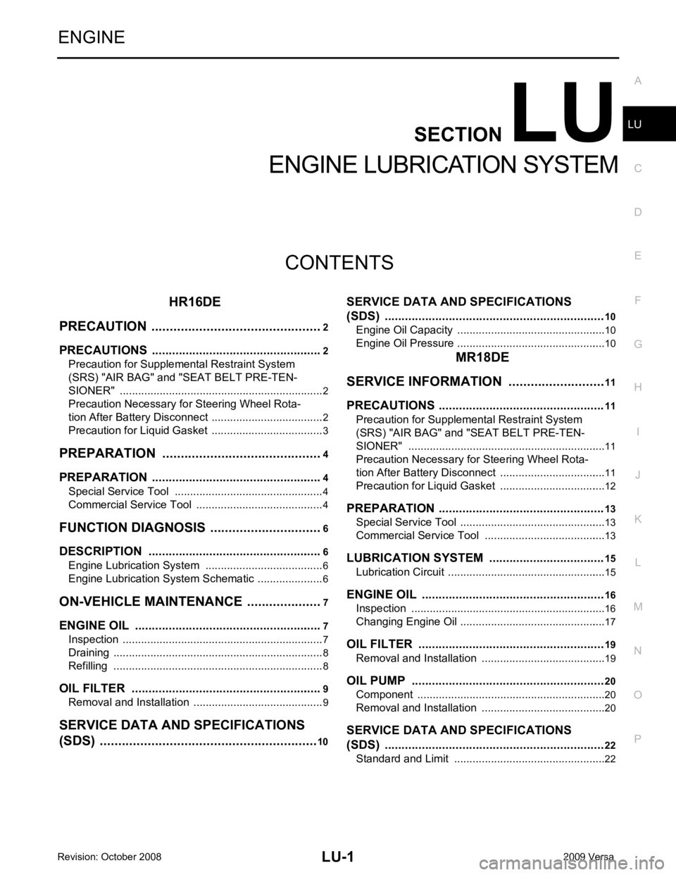
CONTENTS
ENGINE LUBRICATION SYSTEM
HR16DE
PRECAUTION ....... ........................................
2
PRECAUTIONS .............................................. .....2
Precaution for Supplemental Restraint System
(SRS) "AIR BAG" and "SEAT BELT PRE-TEN-
SIONER" ............................................................. ......
2
Precaution Necessary fo r Steering Wheel Rota-
tion After Battery Disconnect ............................... ......
2
Precaution for Liquid Gasket ............................... ......3
PREPARATION .... ........................................4
PREPARATION .............................................. .....4
Special Service Tool ........................................... ......4
Commercial Service Tool .................................... ......4
FUNCTION DIAGNOSIS .. .............................6
DESCRIPTION ............................................... .....6
Engine Lubrication System ................................. ......6
Engine Lubrication System Schematic ................ ......6
ON-VEHICLE MAINTENA NCE .....................7
ENGINE OIL ................................................... .....7
Inspection ............................................................ ......7
Draining ............................................................... ......8
Refilling ............................................................... ......8
OIL FILTER .................................................... .....9
Removal and Installation ...........................................9
SERVICE DATA AND SPECIFICATIONS
(SDS) ......... ................................. ..................10 SERVICE DATA AND SPECIFICATIONS
(SDS) ................................................................. 10
Engine Oil Capacity ............................................. ....10
Engine Oil Pressure ............................................. ....10
MR18DE
SERVICE INFORMATION .. .........................11
PRECAUTIONS ................................................. 11
Precaution for Supplemental Restraint System
(SRS) "AIR BAG" and "SEAT BELT PRE-TEN-
SIONER" ............................................................. ....
11
Precaution Necessary for Steering Wheel Rota-
tion After Battery Disconnect ............................... ....
11
Precaution for Liquid Gasket ............................... ....12
PREPARATION ................................................. 13
Special Service Tool ............................................ ....13
Commercial Service Tool .................................... ....13
LUBRICATION SYSTEM .................................. 15
Lubrication Circuit ................................................ ....15
ENGINE OIL ...................................................... 16
Inspection ............................................................ ....16
Changing Engine Oil ............................................ ....17
OIL FILTER ....................................................... 19
Removal and Installation ..................................... ....19
OIL PUMP ......................................................... 20
Component .......................................................... ....20
Removal and Installation ..................................... ....20
SERVICE DATA AND SPECIFICATIONS
(SDS) ................................................................. 22
Standard and Limit .............................................. ....22