Page 3095 of 4331
![NISSAN TIIDA 2009 Service Repair Manual EM-148< SERVICE INFORMATION >
[MR18DE]
OIL PAN
3. Remove flywheel (M/T models) or drive plate (CVT or A/T models). Refer to EM-199, " Component " .
4. Remove oil filter using Tool.
CAUTION:
When remo](/manual-img/5/57398/w960_57398-3094.png "NISSAN TIIDA 2009 Service Repair Manual EM-148< SERVICE INFORMATION >
[MR18DE]
OIL PAN
3. Remove flywheel (M/T models) or drive plate (CVT or A/T models). Refer to EM-199, \" Component \" .
4. Remove oil filter using Tool.
CAUTION:
When remo")
EM-148< SERVICE INFORMATION >
[MR18DE]
OIL PAN
3. Remove flywheel (M/T models) or drive plate (CVT or A/T models). Refer to EM-199, " Component " .
4. Remove oil filter using Tool.
CAUTION:
When removing, prepare a shop cloth to ab sorb any engine oil leakage or spillage.
5. Remove oil pan (lower) bolts in reverse order as shown.
6. After removing the bolts and nuts, separate the mating surface and remove the sealant using Tool.
• Slide (2) the Tool by tapping (1) its side with a hammer to remove the oil pan (lower) from the oil pan (upper).
CAUTION:
Be careful not to damage the mating surfaces.
7. Remove the following parts: • Front cover, timing chain, oil pump drive chain; Refer to EM-160 .
8. Remove oil pump. • Loosen bolts in reverse order as shown.
9. Remove oil pan (upper) bolts in reverse order as shown. Tool number : KV10115801 ( — )
: Engine front PBIC3146J
Tool number : KV10111100 (J-37228)
WBIA0566E
1 : Oil pump
2 : Oil pan (upper)
: Engine front PBIC3532J
: Engine front
PBIC3533J
Page 3108 of 4331
EM
NP
O
Removal and Installation
INFOID:0000000004307143
CAUTION:
The rotating direction indicated in the text indicates all directions seen from the engine front.
REMOVAL 1. Remove front RH wheel. Refer to WT-7, " Rotation " .
2. Remove front fender protector (RH). Refer to EI-24, " Removal and Installation " .
3. Drain engine oil. Refer to LU-17, " Changing Engine Oil " .
CAUTION:
Perform this step when engine is cold.
4. Remove the following parts. • Rocker cover: Refer to EM-153, " Component " .
• Drive belt: Refer to EM-136, " Removal and Installation " .
• Water pump pulley: Refer to CO-43, " Component " .
• Ground cable (between engine bracket (RH) and radiator core support)
5. Support the bottom surface of engine using a transmission jack, and then remove the engine bracket and insulator (RH). Refer to EM-195, " Component " .
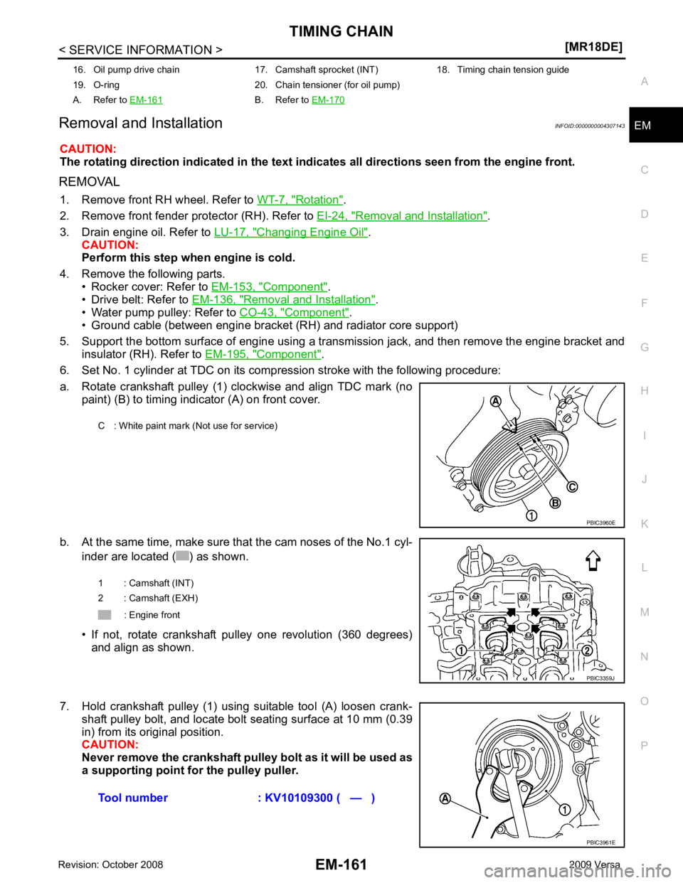
6. Set No. 1 cylinder at TDC on its compression stroke with the following procedure:
a. Rotate crankshaft pulley (1) clockwise and align TDC mark (no paint) (B) to timing indicator (A) on front cover.
b. At the same time, make sure that the cam noses of the No.1 cyl- inder are located ( ) as shown.
• If not, rotate crankshaft pulley one revolution (360 degrees) and align as shown.
7. Hold crankshaft pulley (1) using suitable tool (A) loosen crank- shaft pulley bolt, and locate bolt seating surface at 10 mm (0.39
in) from its original position.
CAUTION:
Never remove the crankshaft pulley bolt as it will be used as
a supporting point for the pulley puller.
16. Oil pump drive chain 17. Camshaft sprocket (INT) 18. Timing chain tension guide
19. O-ring 20. Chain tensioner (for oil pump)
A. Refer to EM-161 B. Refer to
EM-170 C : White paint mark (Not use for service)
Page 3117 of 4331
Fuel Pressure Check " (Type 1) or
EC-1086, " Fuel Pressure
Check " (Type 2).
2. Disconnect negative battery terminal. Refer to SC-7, " Removal and Installation " .
3. Remove front RH wheel. Refer to WT-7 .
4. Remove front fender protector (RH). Refer to EI-24 .
5. Drain engine coolant. Refer to CO-35 .
NOTE:
Perform this step when engine is cold.
6. Remove the following parts. • Intake manifold; Refer to EM-141 .
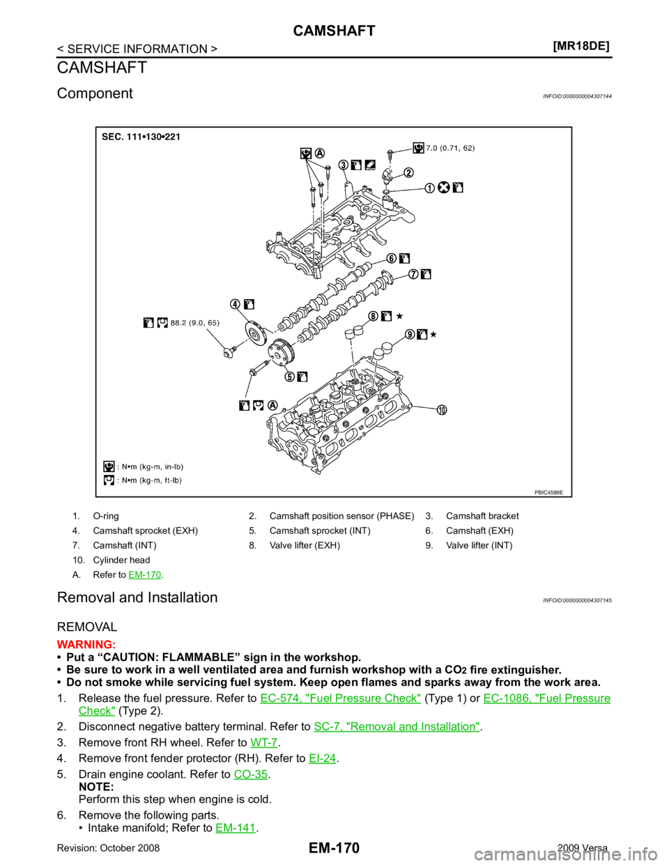
1. O-ring 2. Camshaft po
sition sensor (PHASE) 3. Camshaft bracket
4. Camshaft sprocket (EXH) 5. Camshaft sprocket (INT) 6. Camshaft (EXH)
7. Camshaft (INT) 8. Valve lifter (EXH) 9. Valve lifter (INT)
10. Cylinder head
A. Refer to EM-170 .
Page 3130 of 4331
![NISSAN TIIDA 2009 Service Repair Manual OIL SEAL
EM-183
< SERVICE INFORMATION >
[MR18DE] C
D E
F
G H
I
J
K L
M A EM
NP
O
• Drive belt; Refer to
EM-136, " Component " .
• Crankshaft pulley; Refer to EM-160, " Component " .
2. Remove fr](/manual-img/5/57398/w960_57398-3129.png "NISSAN TIIDA 2009 Service Repair Manual OIL SEAL
EM-183
< SERVICE INFORMATION >
[MR18DE] C
D E
F
G H
I
J
K L
M A EM
NP
O
• Drive belt; Refer to
EM-136, \" Component \" .
• Crankshaft pulley; Refer to EM-160, \" Component \" .
2. Remove fr")
OIL SEAL
EM-183
< SERVICE INFORMATION >
[MR18DE] C
D E
F
G H
I
J
K L
M A EM
NP
O
• Drive belt; Refer to
EM-136, " Component " .
• Crankshaft pulley; Refer to EM-160, " Component " .
2. Remove front oil seal using a suitable tool. CAUTION:
Be careful not to damage front cover and crankshaft.
INSTALLATION 1. Apply new engine oil to new front oil seal joint surface and seal lip.
2. Install front oil seal so that each seal lip is oriented as shown.
• Install front oil seal (2) using a suitable tool with outer diameter57 mm (2.24 in) and inner diameter 45 mm (1.77 in) (A) to the
dimension as shown.
CAUTION:
• Be careful not to damage front cover and crankshaft.
• Press-fit oil seal straight to avoid causing burrs or tilting.
• Do not touch grease applied on oil seal lip.
3. Installation of the remaining components is in the reverse order of removal.
Removal and Installation of Rear Oil Seal INFOID:0000000004307149
REMOVAL 1. Remove transaxle assembly. Refer to MT-58 (M/T models),
AT-232 (A/T models),
CVT-182 or
CVT-354 (CVT models).
2. Remove clutch cover and clutch disk (M/T models). Refer to CL-15 .
3. Remove drive plate (A/T or CVT models) or flywheel (M/T models). Refer to EM-199, " Component " .
4. Remove rear oil seal with a suitable tool. CAUTION:
Be careful not to damage crankshaft and cylinder block.
INSTALLATION 1. Apply the liquid gasket lightly to entire outside area of new rear oil seal. Use Genuine Silicone RTV Seal ant or equivalent. Refer to GI-42, " Recommended Chemical Prod-
uct and Sealant " .
A : Dust seal lip
B : Oil seal lip
: Engine front
: Engine rear PBIC3485J
1 : Front cover
: Engine front
Within 0.3 mm (0.012 in) toward engine front
Within 0.5 mm (0.020 in) toward engine rear PBIC3729E
Page 3142 of 4331
EM
NP
O
ENGINE ASSEMBLY
Component INFOID:0000000004307156
Removal and Installation INFOID:0000000004307157
WARNING:
• Situate the vehicle on a flat and solid surface.
• Place chocks at front and back of rear wheels.
• Attach proper slingers and bolts described in P ARTS CATALOG if engine slingers are not equipped.
CAUTION:
• Always be careful to work safely, avoid forceful or uninstructed operations.
• Do not start working until exhaust system and coolant are cool enough.
• If items or work required are not covered by th e engine section, follow the applicable procedures.
• Always use the support poin t specified for lifting.
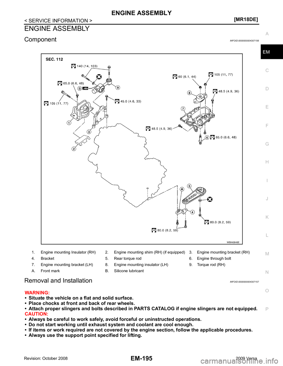
1. Engine mounting Insulator (RH) 2. Engine mounting shim (RH) (if equipped) 3. Engine mounting bracket (RH)
4. Bracket 5. Rear torque rod 6. Engine through bolt
7. Engine mounting bracket (LH) 8. Engine mounting insulator (LH) 9. Torque rod (RH)
A. Front mark B. Silicone lubricant
Page 3147 of 4331
.
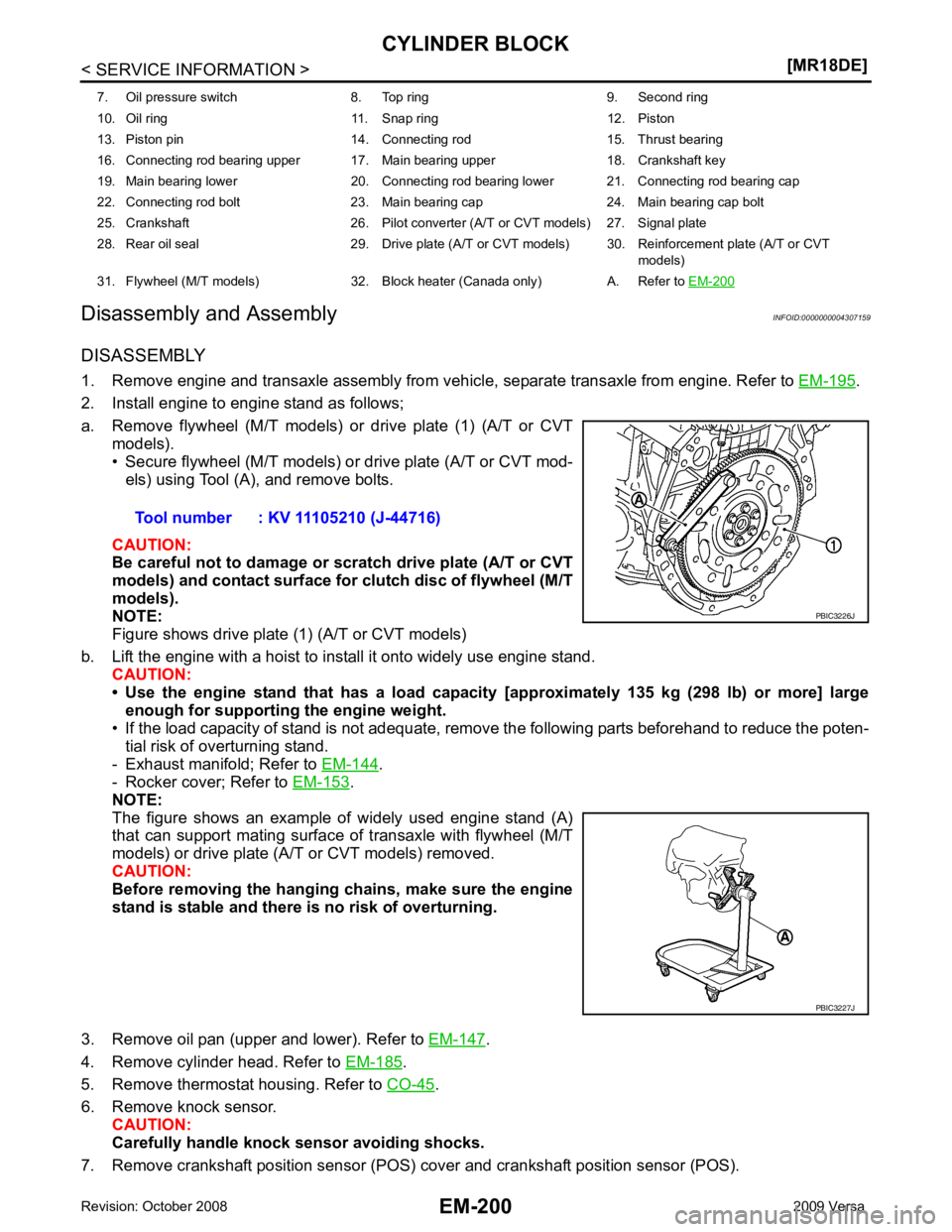
2. Install engine to engine stand as follows;
a. Remove flywheel (M/T models) or drive plate (1) (A/T or CVT models).
• Secure flywheel (M/T models) or drive plate (A/T or CVT mod-
els) using Tool (A), and remove bolts.
CAUTION:
Be careful not to damage or scratch drive plate (A/T or CVT
models) and contact surface for clutch disc of flywheel (M/T
models).
NOTE:
Figure shows drive plate (1) (A/T or CVT models)
b. Lift the engine with a hoist to install it onto widely use engine stand. CAUTION:
• Use the engine stand that has a load capacity [approximately 135 kg (298 lb) or more] large
enough for supporting the engine weight.
• If the load capacity of stand is not adequate, remo ve the following parts beforehand to reduce the poten-
tial risk of overturning stand.
- Exhaust manifold; Refer to EM-144 .
- Rocker cover; Refer to EM-153 .
NOTE:
The figure shows an example of widely used engine stand (A)
that can support mating surface of transaxle with flywheel (M/T
models) or drive plate (A/T or CVT models) removed.
CAUTION:
Before removing the hanging chains, make sure the engine
stand is stable and there is no risk of overturning.
3. Remove oil pan (upper and lower). Refer to EM-147 .
4. Remove cylinder head. Refer to EM-185 .
5. Remove thermostat housing. Refer to CO-45 .
6. Remove knock sensor. CAUTION:
Carefully handle knock sensor avoiding shocks.
7. Remove crankshaft position sensor (POS) cover and crankshaft position sensor (POS).
7. Oil pressure switch 8. Top ring 9. Second ring
10. Oil ring 11. Snap ring 12. Piston
13. Piston pin 14. Connecting rod 15. Thrust bearing
16. Connecting rod bearing upper 17. Main bearing upper 18. Crankshaft key
19. Main bearing lower 20. Connecting rod bearing lower 21. Connecting rod bearing cap
22. Connecting rod bolt 23. Main bearing cap 24. Main bearing cap bolt
25. Crankshaft 26. Pilot converter (A/T or CVT models) 27. Signal plate
28. Rear oil seal 29. Drive plate (A/T or CVT models) 30. Reinforcement plate (A/T or CVT models)
31. Flywheel (M/T models) 32. Block heater (Canada only) A. Refer to EM-200 PBIC3227J
Page 3172 of 4331
![NISSAN TIIDA 2009 Service Repair Manual EM
NP
O
• Measure the outer diameters [(d
1), (d 2)] at two positions as shown.
• If reduction appears in places other than (B) range, regard it as (d 2).
• If it exceeds the limi](/manual-img/5/57398/w960_57398-3171.png "NISSAN TIIDA 2009 Service Repair Manual EM
NP
O
• Measure the outer diameters [(d
1), (d 2)] at two positions as shown.
• If reduction appears in places other than (B) range, regard it as (d 2).
• If it exceeds the limi")
EM
NP
O
• Measure the outer diameters [(d
1), (d 2)] at two positions as shown.
• If reduction appears in places other than (B) range, regard it as (d 2).
• If it exceeds the limit (a large difference in dimensions), replace main bearing cap bolt with a new one.
CONNECTING ROD BOLT OUTER DIAMETER • Measure the outer diameter (d) at position as shown.
• If reduction appears in a position other than (d), regard it as (d).
• When (d) exceeds the limit (when it becomes thinner), replace connecting rod bolt with a new one.
CLOGGED OR DAMAGED OIL FILTER (FOR INTAKE VALVE TIMING CONTROL)
• Make sure that there is no foreign material on the oil filter and check it for clogging.
- Clean it if necessary.
• Check the oil filter for damage.
- Replace it if necessary.
FLYWHEEL DEFLECTION (M/T MODELS) • Measure the deflection of flywheel contact surface to clutch with a dial indicator (A).
• Measure the deflection at 210 mm (8.27 in) diameter.
• If measured value is out of the standard, replace flywheel.
• If a trace of burn or discolorati on is found on the surface, repair it
with sandpaper.
CAUTION:
When measuring, keep magnetic fields (such as dial indicator
stand) away from signal plate of the rear end of crankshaft.
MOVEMENT AMOUNT OF FLYWHEEL (M/T MODELS) CAUTION:
Never disassemble double mass flywheel.
Movement Amount of Thrust (Fore-and-Aft) Direction • Measure the movement amount of thrust (fore-and-af t) direction when 100 N (10.2 kg, 22 lb) force is added
at the portion of 125 mm (4.92 in) radi us from the center of flywheel.
A : (d1) measuring position
B : (d2) measuring position
Limit [(d 1) – (d 2)]: 0.15 mm (0.0059 in) PBIC3273J
Page 3184 of 4331
EM
NP
O
Unit: mm (in)
FLYWHEEL Unit: mm (in)
Connecting rod bearing oil clearance
Standard 0.037 - 0.047 (0.0015 - 0.0019)
Limit 0.07 (0.0028) Items Standard Limit
Flywheel deflection — 0.45 (0.0177) or less
Movement amount in thrust direction 1.8 (0.071) or less —
Movement amount in radial direction — 33.2 (1.307) or less