2009 NISSAN TIIDA wheel
[x] Cancel search: wheelPage 3206 of 4331
FAX
N
O P
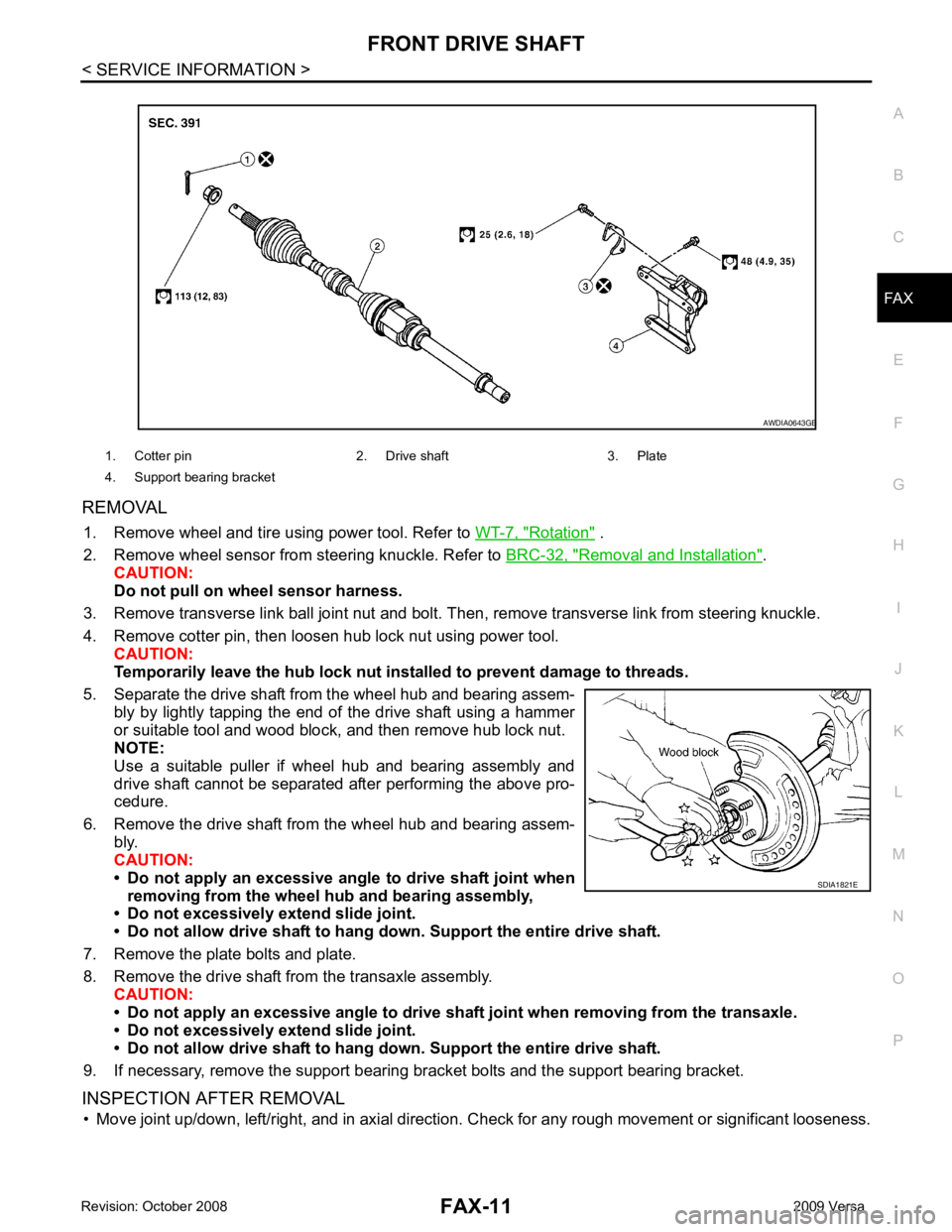
REMOVAL
1. Remove wheel and tire using power tool. Refer to WT-7, " Rotation " .
2. Remove wheel sensor from steering knuckle. Refer to BRC-32, " Removal and Installation " .
CAUTION:
Do not pull on wheel sensor harness.
3. Remove transverse link ball joint nut and bolt. Then, remove transverse link from steering knuckle.
4. Remove cotter pin, then loosen hub lock nut using power tool. CAUTION:
Temporarily leave the hub lock nut inst alled to prevent damage to threads.
5. Separate the drive shaft from the wheel hub and bearing assem- bly by lightly tapping the end of the drive shaft using a hammer
or suitable tool and wood block, and then remove hub lock nut.
NOTE:
Use a suitable puller if wheel hub and bearing assembly and
drive shaft cannot be separated after performing the above pro-
cedure.
6. Remove the drive shaft from the wheel hub and bearing assem- bly.
CAUTION:
• Do not apply an excessive angle to drive shaft joint when
removing from the wheel hub and bearing assembly,
• Do not excessively extend slide joint.
• Do not allow drive shaft to hang do wn. Support the entire drive shaft.
7. Remove the plate bolts and plate.
8. Remove the drive shaft from the transaxle assembly. CAUTION:
• Do not apply an excessive angle to drive shaf t joint when removing from the transaxle.
• Do not excessively extend slide joint.
• Do not allow drive shaft to hang do wn. Support the entire drive shaft.
9. If necessary, remove the support bearing bracket bolts and the support bearing bracket.
INSPECTION AFTER REMOVAL • Move joint up/down, left/right, and in axial direction. Check for any rough movement or significant looseness.
1. Cotter pin 2. Drive shaft 3. Plate
4. Support bearing bracket B
Page 3214 of 4331
FRONT DRIVE SHAFT
FAX-19
< SERVICE INFORMATION >
C
E F
G H
I
J
K L
M A
B FAX
N
O P
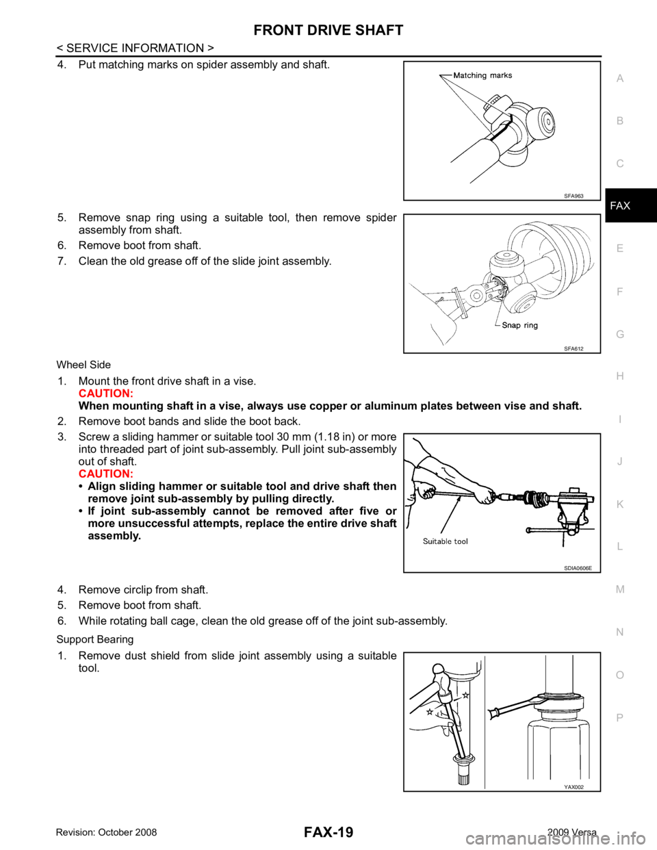
4. Put matching marks on spider assembly and shaft.
5. Remove snap ring using a suitable tool, then remove spider assembly from shaft.
6. Remove boot from shaft.
7. Clean the old grease off of the slide joint assembly.
Wheel Side 1. Mount the front drive shaft in a vise. CAUTION:
When mounting shaft in a vise, always use copper or alum inum plates between vise and shaft.
2. Remove boot bands and slide the boot back.
3. Screw a sliding hammer or suitable tool 30 mm (1.18 in) or more into threaded part of joint sub-assembly. Pull joint sub-assembly
out of shaft.
CAUTION:
• Align sliding hammer or suitab le tool and drive shaft then
remove joint sub-assembly by pulling directly.
• If joint sub-assembly cannot be removed after five or more unsuccessful attempts, replace the entire drive shaft
assembly.
4. Remove circlip from shaft.
5. Remove boot from shaft.
6. While rotating ball cage, clean the old grease off of the joint sub-assembly.
Support Bearing 1. Remove dust shield from slide joint assembly using a suitable tool. SFA963
SFA612
SDIA0606E
YAX002
Page 3217 of 4331
FAX-22< SERVICE INFORMATION >
FRONT DRIVE SHAFT
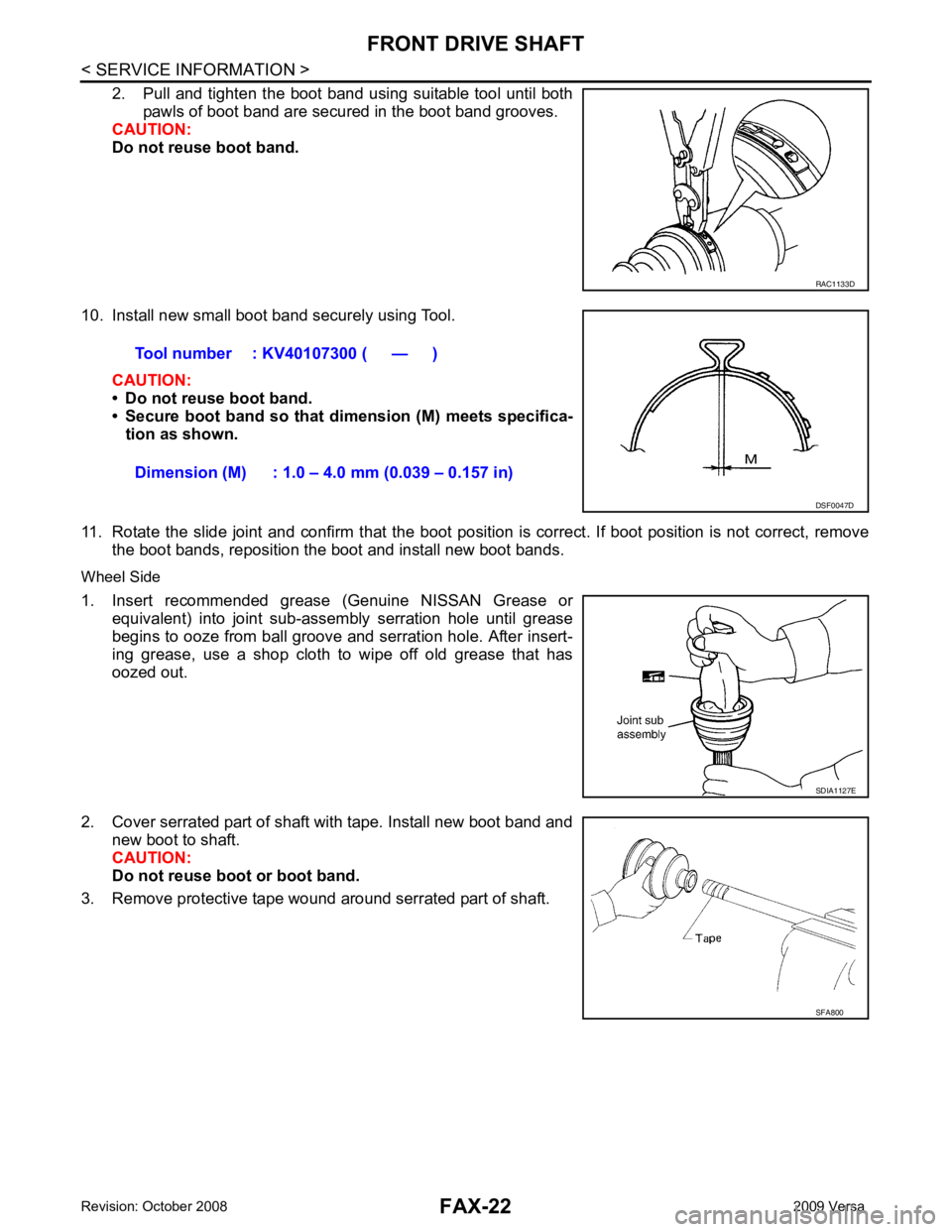
2. Pull and tighten the boot band using suitable tool until both pawls of boot band are secured in the boot band grooves.
CAUTION:
Do not reuse boot band.
10. Install new small boot band securely using Tool. CAUTION:
• Do not reuse boot band.
• Secure boot band so that dimension (M) meets specifica-
tion as shown.
11. Rotate the slide joint and confirm that the boot posit ion is correct. If boot position is not correct, remove
the boot bands, reposition the boot and install new boot bands.
Wheel Side
1. Insert recommended grease (Genuine NISSAN Grease or
equivalent) into joint sub-assembly serration hole until grease
begins to ooze from ball groove and serration hole. After insert-
ing grease, use a shop cloth to wipe off old grease that has
oozed out.
2. Cover serrated part of shaft with tape. Install new boot band and new boot to shaft.
CAUTION:
Do not reuse boot or boot band.
3. Remove protective tape wound around serrated part of shaft. RAC1133D
Tool number : KV40107300 ( — )
Dimension (M) : 1.0 – 4.0 mm (0.039 – 0.157 in) DSF0047D
SDIA1127E
SFA800
Page 3220 of 4331
SERVICE DATA AND SPECIFICATIONS (SDS)
FAX-25
< SERVICE INFORMATION >
C
E F
G H
I
J
K L
M A
B FAX
N
O P
SERVICE DATA AND SPECIFICATIONS (SDS)
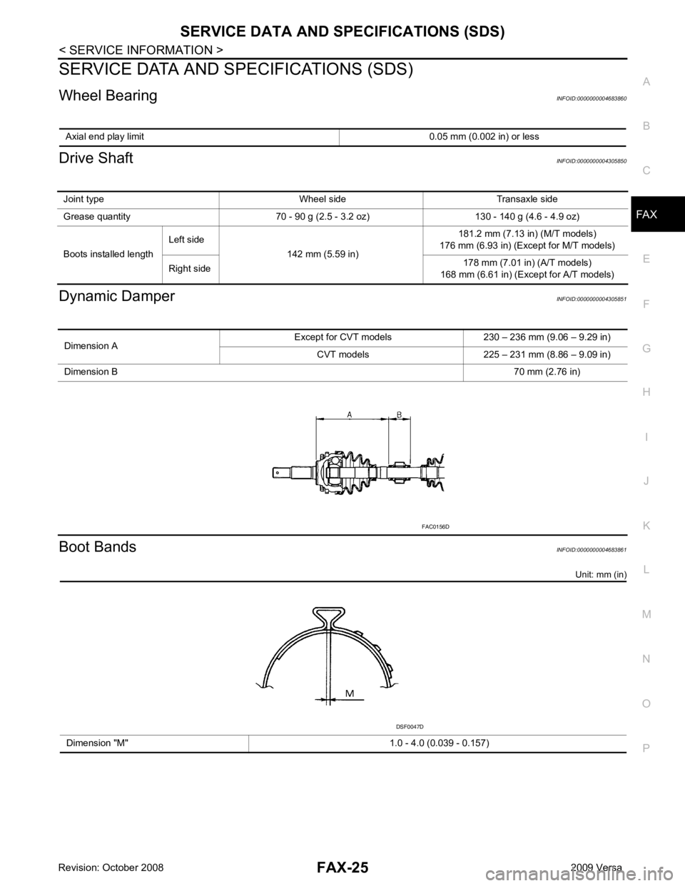
Wheel Bearing INFOID:0000000004683860
Drive Shaft INFOID:0000000004305850
Dynamic Damper INFOID:0000000004305851
Boot Bands INFOID:0000000004683861
Unit: mm (in)
Axial end play limit
0.05 mm (0.002 in) or lessJoint type Wheel side Transaxle side
Grease quantity 70 - 90 g (2.5 - 3.2 oz) 130 - 140 g (4.6 - 4.9 oz)
Boots installed length Left side
142 mm (5.59 in) 181.2 mm (7.13 in) (M/T models)
176 mm (6.93 in) (Except for M/T models)
Right side 178 mm (7.01 in) (A/T models)
168 mm (6.61 in) (Exc ept for A/T models)Dimension A
Except for CVT models 230 – 236 mm (9.06 – 9.29 in)
CVT models 225 – 231 mm (8.86 – 9.09 in)
Dimension B 70 mm (2.76 in)FAC0156D
Dimension "M" 1.0 - 4.0 (0.039 - 0.157) DSF0047D
Page 3235 of 4331

FSU
N
O P
CONTENTS
FRONT SUSPENSION
SERVICE INFORMATION .. ..........................2
PRECAUTIONS .............................................. .....2
Precaution for Supplemental Restraint System
(SRS) "AIR BAG" and "SEAT BELT PRE-TEN-
SIONER" ............................................................. ......
2
Precaution Necessary fo r Steering Wheel Rota-
tion After Battery Disconnect ............................... ......
2
Precaution for Procedure without Cowl Top Cover ......3
Cautions .............................................................. ......3
PREPARATION .............................................. .....4
Special Service Tool ........................................... ......4
Commercial Service Tool .................................... ......4
NOISE, VIBRATION AND HARSHNESS
(NVH) TROUBLESHOOTING ........................ .....6
NVH Troubleshooting Chart ................................ ......6
FRONT SUSPENSION ASSEMBLY .............. .....7 On-Vehicle Inspection and Service .....................
.....7
Wheel Alignment Inspecti on .....................................7
Component .......................................................... ....10
Removal and Installation ..................................... ....11
COIL SPRING AND STRUT .............................. 12
Removal and Installation ..................................... ....12
Disassembly and Assembly ................................. ....12
TRANSVERSE LI NK ......................................... 15
Removal and Installation ..................................... ....15
STABILIZER BAR ............................................. 16
Removal and Installation ..................................... ....16
SERVICE DATA AND SPECIFICATIONS
(SDS) ................................................................. 17
Wheel Alignment (Unladen*) ............................... ....17
Ball Joint .............................................................. ....18
Wheelarch Height (Unladen*) .............................. ....19
Page 3237 of 4331
PRECAUTIONS
FSU-3
< SERVICE INFORMATION >
C
D
F
G H
I
J
K L
M A
B FSU
N
O P
5. When the repair work is completed, return the ignition switch to the
″LOCK ″ position before connecting
the battery cables. (At this time, the steering lock mechanism will engage.)
6. Perform a self-diagnosis check of al l control units using CONSULT-III.
Precaution for Procedur e without Cowl Top Cover INFOID:0000000004305858
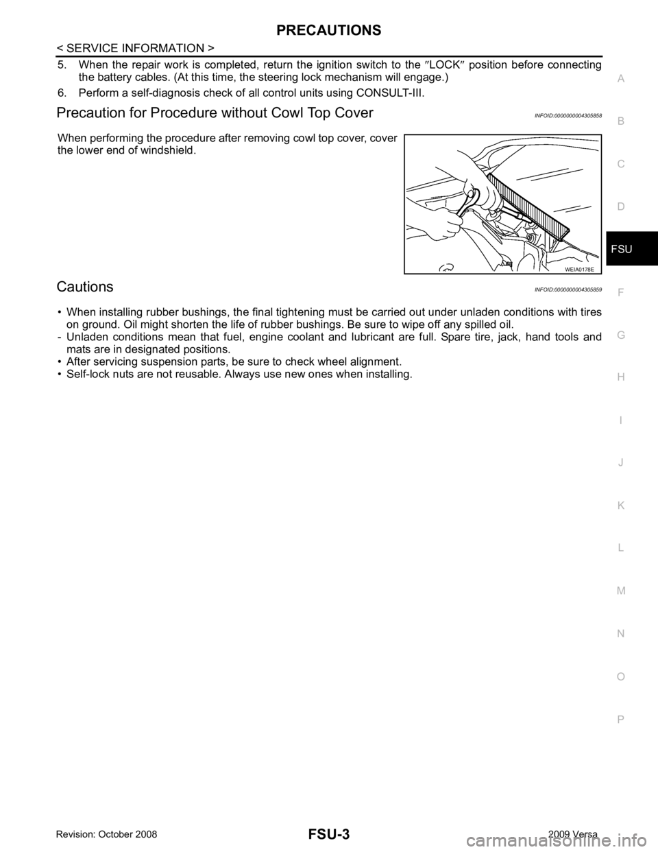
When performing the procedure after removing cowl top cover, cover
the lower end of windshield.
Cautions INFOID:0000000004305859
• When installing rubber bushings, the final tightening mu st be carried out under unladen conditions with tires
on ground. Oil might shorten the life of rubber bushings. Be sure to wipe off any spilled oil.
- Unladen conditions mean that fuel, engine coolant and l ubricant are full. Spare tire, jack, hand tools and
mats are in designated positions.
• After servicing suspension parts, be sure to check wheel alignment.
• Self-lock nuts are not reusable. A lways use new ones when installing. WEIA0178E
Page 3240 of 4331
FSU-12FSU-10FSU-10FSU-19FSU-10FSU-17FSU-16
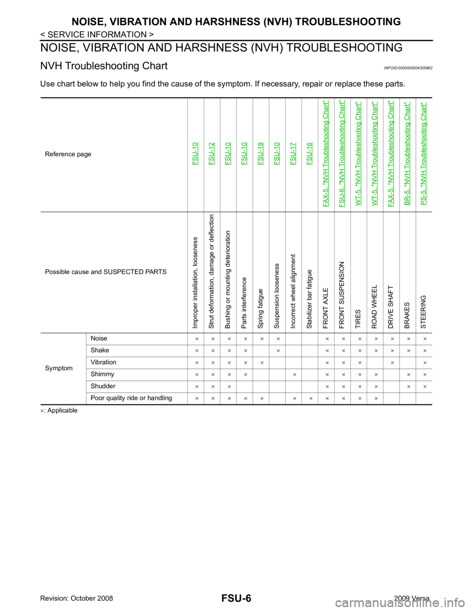
FAX-5, "
NVH Troubleshooting Chart
"
FSU-6, "
NVH Troubleshooting Chart
"
WT-5, "
NVH Troubleshooting Chart
"
WT-5, "
NVH Troubleshooting Chart
"
FAX-5, "
NVH Troubleshooting Chart
"
BR-5, "
NVH Troubleshooting Chart
"
PS-5, "
NVH Troubleshooting Chart
"Possible cause an
d SUSPECTED PARTS
Improper installation, looseness
Strut deformation, damage or deflection
Bushing or mounting deterioration
Parts interference
Spring fatigue
Suspension looseness
Incorrect wheel alignment
Stabilizer bar fatigue
FRONT AXLE
FRONT SUSPENSION
TIRES
ROAD WHEEL
DRIVE SHAFT
BRAKES
STEERING
Symptom Noise
× × × × × × × × × × × × ×
Shake × × × × × × × × × × × ×
Vibration × × × × × × × × × ×
Shimmy × × × × × × × × × × ×
Shudder × × × × × × × × ×
Poor quality ride or handling × × × × × × × × × × ×
Page 3241 of 4331
FSU
N
O P
FRONT SUSPENSION ASSEMBLY
On-Vehicle Inspection and Service INFOID:0000000004305863
Make sure the mounting conditions (looseness, back lash) of each component and component conditions
(wear, damage) are normal.
INSPECTION OF LOWER BALL JOINT END PLAY 1. Set front wheels in a straight-ahead position. Do not depress brake pedal.
2. Place an iron bar or similar tool bet ween transverse link and steering knuckle.
3. Measure axial end play by prying it up and down.
CAUTION:
Be careful not to damage ball joint boot. Do not damage the installation position by applying
excessive force.
STRUT INSPECTION Check for oil leakage, damage and replace as necessary.
Wheel Alignment Inspection INFOID:0000000004305864
PRELIMINARY INSPECTION WARNING:
Always adjust the alignment with the vehicle on a flat surface.
NOTE:
If alignment is out of specification, inspect and r eplace any damaged or worn rear suspension parts before
making any adjustments.
1. Check and adjust the wheel alignment with the vehicle under unladen conditions. “Unladen conditions”
means that the fuel, coolant, and lubricant are full; and that the spare tire, jack, hand tools and mats are in
their designated positions.
2. Check the tires for incorrect air pressure and excessive wear.
3. Check the wheels for run out and damage. Refer to WT-6, " Inspection " .
4. Check the wheel bearing axial end play. Refer to FAX-6, " On-Vehicle Inspection and Service " .
5. Check the shock absorbers for leaks or damage.
6. Check each mounting point of the suspension components for any excessive looseness or damage.
7. Check each link, arm, and the suspension member for any damage.
8. Check the vehicle height. Refer to FSU-19, " Wheelarch Height (Unladen*) " .
GENERAL INFORMATION AND RECOMMENDATIONS 1. A Four-Wheel Thrust Alignment should be performed. • This type of alignment is re commended for any NISSAN vehicle.
• The four-wheel “thrust” process helps ensure that the vehicle is properly aligned and the steering wheel
is centered.
• The alignment machine itself should be ca pable of accepting any NISSAN vehicle.
• The alignment machine should be checked to ensure that it is level.
2. Make sure the alignment machine is properly calibrated. • Your alignment machine should be regularly calib rated in order to give correct information.
• Check with the manufacturer of your specific a lignment machine for their recommended Service/Cali-
bration Schedule.
THE ALIGNMENT PROCESS IMPORTANT: Use only the alignment specifications listed in this Service Manual. Refer to FSU-17, " Wheel
Alignment (Unladen*) " .
1. When displaying the alignment settings, many alignm ent machines use “indicators”: (Green/red, plus or
minus, Go/No Go). Do NOT use these indicators.
• The alignment specifications programmed into your alignment machine that operate these indicators
may not be correct. Axial end play : 0 mm (0 in)