2009 NISSAN TIIDA wheel
[x] Cancel search: wheelPage 3024 of 4331
EM
NP
O
FRONT OIL SEAL : Remo
val and Installation INFOID:0000000004784303
REMOVAL 1. Remove the following parts: • Front fender protector (RH): Refer to EI-24, " Removal and Installation " .
• Drive belt: Refer to EM-15, " Removal and Installation " .
• Crankshaft pulley: Refer to EM-49, " Exploded View " .
2. Remove front oil seal using a suitable tool. CAUTION:
Be careful not to damage fron t timing chain case and crankshaft.
INSTALLATION 1. Apply new engine oil to both oil seal lip and dust seal lip of new front oil seal.
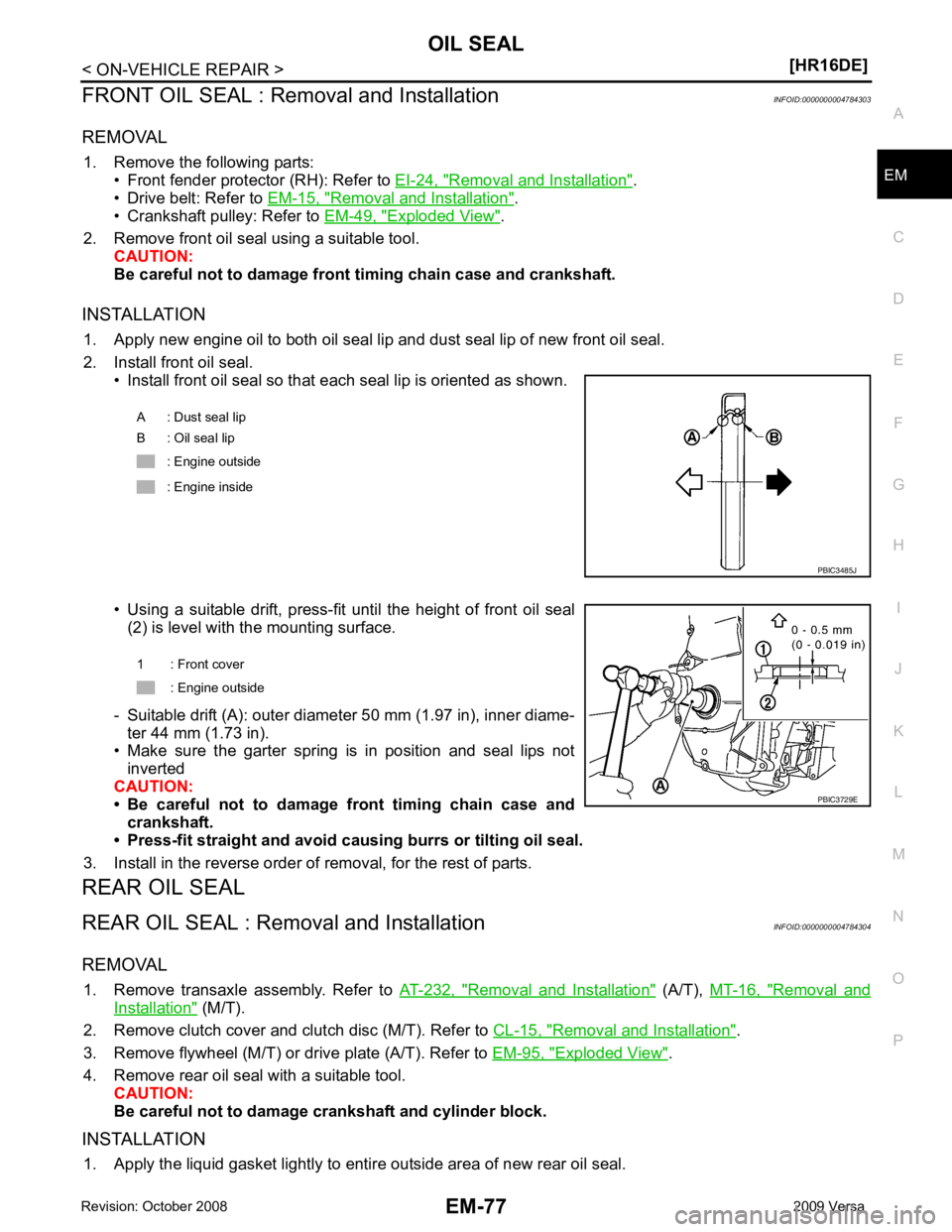
2. Install front oil seal. • Install front oil seal so that each seal lip is oriented as shown.
• Using a suitable drift, press-fit until the height of front oil seal (2) is level with the mounting surface.
- Suitable drift (A): outer diameter 50 mm (1.97 in), inner diame- ter 44 mm (1.73 in).
• Make sure the garter spring is in position and seal lips not
inverted
CAUTION:
• Be careful not to damage front timing chain case and
crankshaft.
• Press-fit straight and avoid cau sing burrs or tilting oil seal.
3. Install in the reverse order of removal, for the rest of parts.
REAR OIL SEAL
REAR OIL SEAL : Removal and Installation INFOID:0000000004784304
REMOVAL 1. Remove transaxle assembly. Refer to AT-232, " Removal and Installation " (A/T),
MT-16, " Removal and
Installation " (M/T).
2. Remove clutch cover and clutch disc (M/T). Refer to CL-15, " Removal and Installation " .
3. Remove flywheel (M/T) or drive plate (A/T). Refer to EM-95, " Exploded View " .
4. Remove rear oil seal with a suitable tool. CAUTION:
Be careful not to damage crankshaft and cylinder block.
INSTALLATION 1. Apply the liquid gasket lightly to entire outside area of new rear oil seal. A : Dust seal lip
B : Oil seal lip
: Engine outside
: Engine inside
Page 3036 of 4331
EM
NP
O
• If items or work required are not covered by the
engine section, follow the procedures in the applica-
ble sections.
• Always use the support poin t specified for lifting.
• Use either 2-pole lift type or separate type lift as best you can. If board-on type is used for unavoid-
able reasons, support at the rear axle jacking point with a transmission jack or similar tool before
starting work, in prepar ation for the backward shif t of center of gravity.
• For supporting points fo r lifting and jacking point at rear axle, refer to GI-38, " Garage Jack and
Safety Stand and 2-Pole Lift " .
REMOVAL
Outline Remove the engine and the transaxle assembly from t he vehicle downward. Separate the engine and the tran-
saxle.
Preparation 1. Remove the hood assembly. Refer to BL-14, " Removal and Installation " .
2. Remove the cowl top cover and cowl top extension assembly. Refer to EI-22, " Removal and Installation " .
3. Release fuel pressure. Refer to EC-498, " Inspection " .
4. Drain engine coolant from radiator. Refer to CO-11, " Changing Engine Coolant " .
CAUTION:
• Perform this step when the engine is cold.
• Never spill engine coolant on drive belt.
5. Drain the transmission fluid. Refer to MT-10, " Draining " (M/T),
AT-17, " Changing A/T Fluid " (A/T).
6. Remove the following parts. • Engine undercover
• Front road wheels and tires: Refer to WT-7, " Rotation " .
• Front fender protector (RH and LH): Refer to EI-24, " Removal and Installation " .
• Battery and battery tray: Refer to SC-7, " Removal and Installation " .
• Drive belt: Refer to EM-15, " Removal and Installation " .
• Air duct and air cleaner case assembly: Refer to EM-26, " Exploded View " .
• Radiator hose (upper and lower): Refer to CO-16, " Component " .
• Disconnect cooling fan controller wiring harness.
• Remove coolant reservoir tank.
• Remove fan shroud and cooling fan assembly. Refer to CO-18, " Component (Models with A/C) " or
CO- 18, " Component (Models without A/C) " .
Engine Room LH 1. Disconnect all connections of engine harness around the engine mounting insulator (LH), and then tem- porarily secure the engine harness into the engine side.
CAUTION:
Protect connectors using a resin bag against foreign materials.
2. Remove ground cable at transaxle side.
3. Disconnect fuel feed hose at engine side. Refer to EM-34, " Exploded View " .
4. Disconnect EVAP purge hose and brake booster vacuum hose.
5. Disconnect heater hoses, and install plugs them to prevent engine coolant from draining. Refer to CO-16," Component " .
6. Disconnect control linkage from transaxle. Refer to AT-212, " Control Device Removal and Installation " (A/
T), MT-13, " Exploded View " (M/T).
7. Disconnect the clutch tube at tr ansmission side (if equipped). Refer to CL-14, " Removal and Installation " .
Engine Room RH 1. Remove ground cable between front cover and vehicle.
2. Remove generator and generator bracket; Refer to SC-25, " Removal and Installation " .
3. Remove A/C compressor with piping connected from t he engine. Temporarily secure it on the vehicle side
with a rope to avoid putting load on it. (if equipped) Refer to MTC-78, " Removal and Installation of Com-
pressor - HR16DE " .
Vehicle Underbody
Page 3040 of 4331
EM
NP
O
DISASSEMBLY AND ASSEMBLY
ENGINE STAND SETTING
Setting INFOID:0000000004784310
NOTE:
Explained here is how to disassemble with engine stand supporting transmission surface. When using differ-
ent type of engine stand, note with difference in steps and etc.
1. Remove the engine and the transaxle assembly from the vehicle, and separate the transaxle from the
engine. Refer to EM-88, " Exploded View " .
2. Remove clutch cover and clutch disc (if equipped). Refer to CL-15, " Removal and Installation " .
3. Remove flywheel or driveplate. • Secure flywheel or driveplate with Tool, and remove bolts.
CAUTION:
• Never disassemble flywheel.
• Never place flywheel or driveplate with signal plate facing down.
• When handling signal plate, take car e not to damage or scratch it.
• Handle signal plate in a manner that prevents it from becoming magnetized.
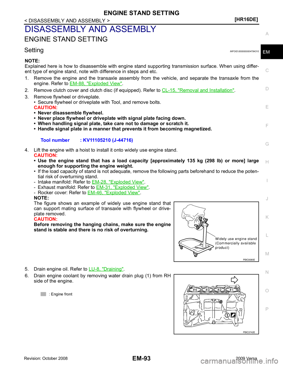
4. Lift the engine with a hoist to install it onto widely use engine stand. CAUTION:
• Use the engine stand that has a load capacity [approximately 135 kg (298 lb) or more] large
enough for supporting the engine weight.
• If the load capacity of stand is not adequate, remove the following parts beforehand to reduce the poten-
tial risk of overturning stand.
- Intake manifold: Refer to EM-28, " Exploded View " .
- Exhaust manifold: Refer to EM-31, " Exploded View " .
- Rocker cover: Refer to EM-46, " Exploded View " .
NOTE:
The figure shows an example of widely use engine stand that
can support mating surface of transaxle with flywheel or drive-
plate removed.
CAUTION:
Before removing the hanging chains, make sure the engine
stand is stable and there is no risk of overturning.
5. Drain engine oil. Refer to LU-8, " Draining " .
6. Drain engine coolant by removing water drain plug (1) from RH side of the engine. Tool number : KV11105210 (J-44716)
Page 3043 of 4331
Removal and Installation " .
2. Remove knock sensor. CAUTION:
Carefully handle knock sensor avoiding shocks.
3. Remove crankshaft position sensor (POS) and cover. CAUTION:
• Avoid impacts such as a dropping.
• Never disassemble.
• Keep it away from metal particles.
• Never place the sensor where it is exposed to magnetism.
4. Remove piston and connecting rod assembly with the following procedure: • Before removing piston and connecting rod assembly, check the connecting rod side clearance. Refer to
EM-103, " Inspection " .
a. Position crankshaft pin corresponding to connecting rod to be removed onto the bottom dead center.
b. Remove connecting rod cap.
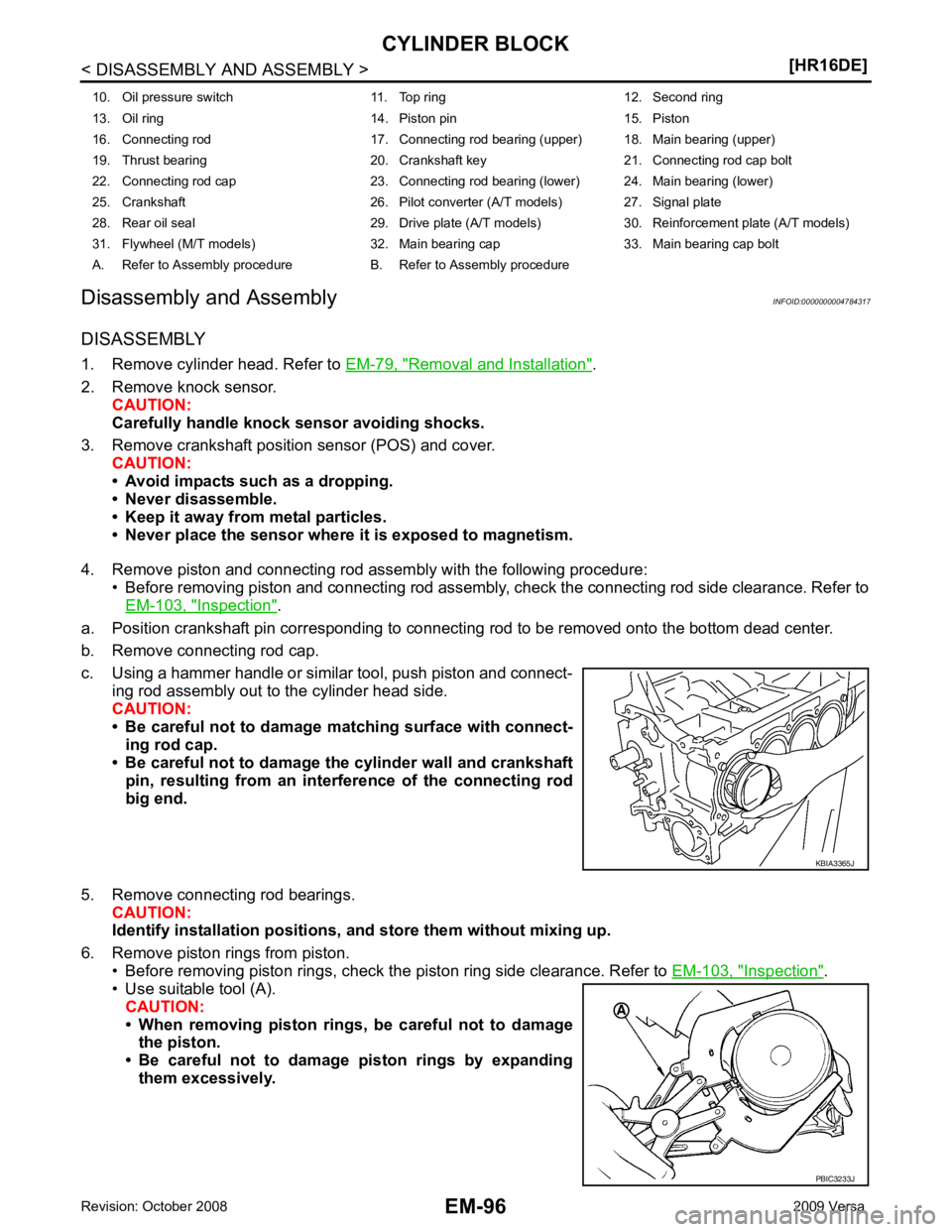
c. Using a hammer handle or similar tool, push piston and connect- ing rod assembly out to the cylinder head side.
CAUTION:
• Be careful not to damage matching surface with connect-
ing rod cap.
• Be careful not to damage the cylinder wall and crankshaft pin, resulting from an inte rference of the connecting rod
big end.
5. Remove connecting rod bearings. CAUTION:
Identify installation positions, and store them without mixing up.
6. Remove piston rings from piston. • Before removing piston rings, check the piston ring side clearance. Refer to EM-103, " Inspection " .
• Use suitable tool (A).
CAUTION:
• When removing piston rings, be careful not to damage the piston.
• Be careful not to damage piston rings by expanding
them excessively.
10. Oil pressure switch 11. Top ring 12. Second ring
13. Oil ring 14. Piston pin 15. Piston
16. Connecting rod 17. Connecting rod bearing (upper) 18. Main bearing (upper)
19. Thrust bearing 20. Crankshaft key 21. Connecting rod cap bolt
22. Connecting rod cap 23. Connecting rod bearing (lower) 24. Main bearing (lower)
25. Crankshaft 26. Pilot converter (A/T models) 27. Signal plate
28. Rear oil seal 29. Drive plate (A/T models) 30. Reinforcement plate (A/T models)
31. Flywheel (M/T models) 32. Main bearing cap 33. Main bearing cap bolt
A. Refer to Assembly procedure B. Refer to Assembly procedure PBIC3233J
Page 3049 of 4331
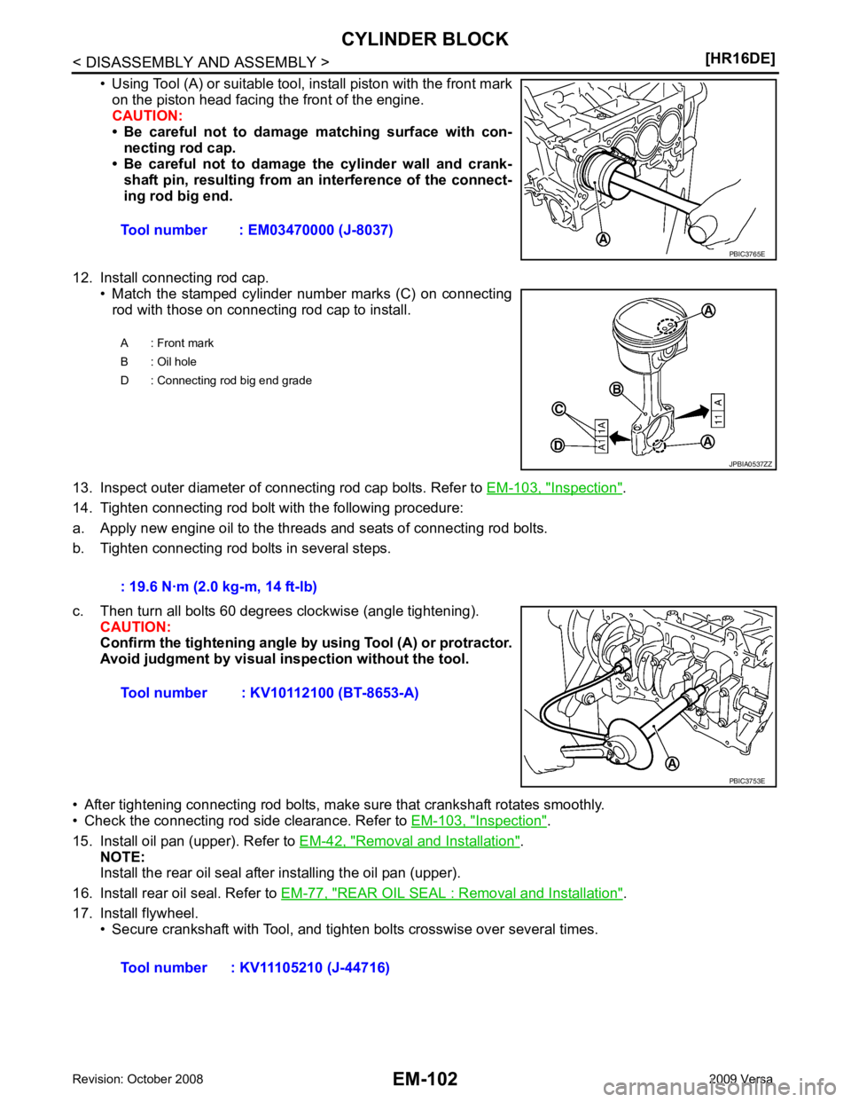
Inspection " .
14. Tighten connecting rod bolt with the following procedure:
a. Apply new engine oil to the threads and seats of connecting rod bolts.
b. Tighten connecting rod bolts in several steps.
c. Then turn all bolts 60 degrees clockwise (angle tightening). CAUTION:
Confirm the tightening angle by using Tool (A) or protractor.
Avoid judgment by visual inspection without the tool.
• After tightening connecting rod bolts, make sure that crankshaft rotates smoothly.
• Check the connecting rod side clearance. Refer to EM-103, " Inspection " .
15. Install oil pan (upper). Refer to EM-42, " Removal and Installation " .
NOTE:
Install the rear oil seal after installing the oil pan (upper).
16. Install rear oil seal. Refer to EM-77, " REAR OIL SEAL : Removal and Installation " .
17. Install flywheel. • Secure crankshaft with Tool, and tighten bolts crosswise over several times.Tool number : EM03470000 (J-8037)
Page 3057 of 4331
![NISSAN TIIDA 2009 Service Repair Manual EM-110< DISASSEMBLY AND ASSEMBLY >
[HR16DE]
CYLINDER BLOCK
CONNECTING ROD BEARING CRUSH HEIGHT
• When connecting rod bearing cap is removed after being tightened to the specified torque with co](/manual-img/5/57398/w960_57398-3056.png "NISSAN TIIDA 2009 Service Repair Manual EM-110< DISASSEMBLY AND ASSEMBLY >
[HR16DE]
CYLINDER BLOCK
CONNECTING ROD BEARING CRUSH HEIGHT
• When connecting rod bearing cap is removed after being tightened to the specified torque with co")
EM-110< DISASSEMBLY AND ASSEMBLY >
[HR16DE]
CYLINDER BLOCK
CONNECTING ROD BEARING CRUSH HEIGHT
• When connecting rod bearing cap is removed after being tightened to the specified torque with connecting rod bearings installed, the
tip end of bearing must protrude. Refer to EM-96, " Disassembly
and Assembly " .
• If the standard is not met, replace connecting rod bearings.
MAIN BEARING CAP BOLT OUTER DIAMETER
• Measure the outer diameters (“d 1”, “d 2”) at two positions as shown.
• If reduction appears in a position other than “d 2 ”, regard it as “d 2”.
• If it exceeds the limit (a large difference in dimensions), replace main bearing cap bolt with a new one.
CONNECTING ROD CAP BOLT OUTER DIAMETER
• Measure the outer diameter “d” at position as shown.
• If reduction appears in a position other than “d”, regard it as “d”.
• When “d” falls below the limit (when it becomes thinner), replace connecting rod cap bolt with a new one.
FLYWHEEL DEFLECTION
• Measure the deflection of flywheel contact surface to clutch with a
dial indicator.
• If measured value is out of the standard, replace flywheel. Standard: There must be crush height. PBIC1646E
Limit (“d
1”–“d 2”): 0.2 mm (0.008 in) PBIC3768E
Limit: 7.75 mm (0.3051 in)
PBIC3769E
Standard : 0.25 mm (0.0098 in) or less.
PBIC2646E
Page 3078 of 4331
![NISSAN TIIDA 2009 Service Repair Manual PREPARATION
EM-131
< SERVICE INFORMATION >
[MR18DE] C
D E
F
G H
I
J
K L
M A EM
NP
O
ST16610001
(J-23907)
Pilot bushing puller Removing crankshaft pilot bushing
KV11103000
( — )
Pulley puller Rem](/manual-img/5/57398/w960_57398-3077.png "NISSAN TIIDA 2009 Service Repair Manual PREPARATION
EM-131
< SERVICE INFORMATION >
[MR18DE] C
D E
F
G H
I
J
K L
M A EM
NP
O
ST16610001
(J-23907)
Pilot bushing puller Removing crankshaft pilot bushing
KV11103000
( — )
Pulley puller Rem")
PREPARATION
EM-131
< SERVICE INFORMATION >
[MR18DE] C
D E
F
G H
I
J
K L
M A EM
NP
O
ST16610001
(J-23907)
Pilot bushing puller Removing crankshaft pilot bushing
KV11103000
( — )
Pulley puller Removing crankshaft pulley
KV991J0050
(J-44626)
Air fuel sensor Socket Loosening or tightening air fuel ratio sen-
sor
a: 22 mm (0.87 in)
KV10114400
(J-38365)
Heated oxygen sensor wrench Loosening or tightening rear heated oxy-
gen sensor
a: 22 mm (0.87 in)
KV11105210
(J-44716)
Stopper plate Securing drive plate and flywheel
KV10115600
(J-38958)
Valve oil seal drift Installing valve oil seal
Use side A.
a: 20 (0.79) dia .
b: 13 (0.51) dia.
c: 10.3 (0.406) dia .
d: 8 (0.31) dia.
e: 10.7 (0.421)
f: 5 (0.20)
KV10115801
( — )
Oil filter wrench Removing and installing oil filter
a: 64.3 mm (2.531 in)
Tool number
(Kent-Moore No.)
Tool name DescriptionNT045
NT676
LBIA0444E
NT636
ZZA0009D
S-NT603
S-NT375
Page 3080 of 4331
![NISSAN TIIDA 2009 Service Repair Manual PREPARATION
EM-133
< SERVICE INFORMATION >
[MR18DE] C
D E
F
G H
I
J
K L
M A EM
NP
O
Valve guide reamer (1): Reaming valve guide inner hole
(2): Reaming hole for oversize valve guide
(J-43897-18)
(J-43](/manual-img/5/57398/w960_57398-3079.png "NISSAN TIIDA 2009 Service Repair Manual PREPARATION
EM-133
< SERVICE INFORMATION >
[MR18DE] C
D E
F
G H
I
J
K L
M A EM
NP
O
Valve guide reamer (1): Reaming valve guide inner hole
(2): Reaming hole for oversize valve guide
(J-43897-18)
(J-43")
PREPARATION
EM-133
< SERVICE INFORMATION >
[MR18DE] C
D E
F
G H
I
J
K L
M A EM
NP
O
Valve guide reamer (1): Reaming valve guide inner hole
(2): Reaming hole for oversize valve guide
(J-43897-18)
(J-43897-12)
Oxygen sensor thread cleaner Reconditioning the exhaust system threads
before installing a new oxygen sensor (Use
with anti-seize lubricant shown below.)
a: J-43897-18 (18 mm dia.) for zirconia ox-
ygen sensor
b: J-43897-12 (12 mm dia.) for titania oxy-
gen sensor
Anti-seize lubricant (Permatex 133AR
or equivalent meeting MIL specifica-
tion MIL-A-907) Lubricating oxygen sensor thread cleaning
tool when reconditioning exhaust system
threads
E20 Torx® Socket
(J-45816) Removing and installing drive plate and fly-
wheel bolts
(Kent-Moore No.)
Tool name Description PBIC4013E
AEM488
AEM489
LBIA0285E