2009 NISSAN TIIDA wheel
[x] Cancel search: wheelPage 1819 of 4331
EC
NP
O
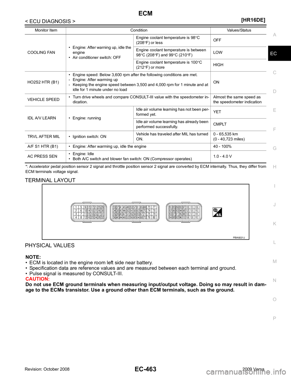
*: Accelerator pedal position sensor 2 signal and throttle position sensor 2 signal are converted by ECM internally. Thus, they
differ from
ECM terminals voltage signal.
TERMINAL LAYOUT
PHYSICAL VALUES NOTE:
• ECM is located in the engine room left side near battery.
• Specification data are reference values and are measured between each terminal and ground.
• Pulse signal is measured by CONSULT-III.
CAUTION:
Do not use ECM ground terminals wh en measuring input/output voltage. Doing so may result in dam-
age to the ECMs transistor. Use a ground ot her than ECM terminals, such as the ground.
COOLING FAN
• Engine: After warning up, idle the
engine
• Air conditioner switch: OFF Engine coolant temperature is 98
°C
(208 °F) or less OFF
Engine coolant temperature is between
98 °C (208 °F) and 99 °C (210 °F) LOW
Engine coolant temperature is 100 °C
(212 °F) or more HIGH
HO2S2 HTR (B1) • Engine speed: Below 3,600 rpm after the following conditions are met.
- Engine: After warming up
- Keeping the engine speed between 3,500 and 4,000 rpm for 1 minute and at idle for 1 minute under no load ON
VEHICLE SPEED • Turn drive wheels and compare CONSULT-III value with the speedometer in-
dication. Almost the same speed as
the speedometer indication
IDL A/V LEARN • Engine: running Idle air volume learning has not been per-
formed yet. YET
Idle air volume learning has already been
performed successfully. CMPLT
TRVL AFTER MIL • Ignition switch: ON Vehicle has traveled after MIL has turned
ON. 0 - 65,535 km
(0 - 40,723 miles)
A/F S1 HTR (B1) • Engine: After warming up, idle the engine 40 - 100%
AC PRESS SEN • Engine: Idle
• Both A/C switch and blower fan switch: ON (Compressor operates) 1.0 - 4.0 V
Monitor Item Condition Values/Status
Page 1922 of 4331
![NISSAN TIIDA 2009 Service Repair Manual EC-566< SERVICE INFOMATION >
[MR TYPE 1]
BASIC SERVICE PROCEDURE
BASIC SERVICE PROCEDURE
Basic Inspection INFOID:00000000045370431.
INSPECTION START
1. Check service records for any recent repairs tha](/manual-img/5/57398/w960_57398-1921.png "NISSAN TIIDA 2009 Service Repair Manual EC-566< SERVICE INFOMATION >
[MR TYPE 1]
BASIC SERVICE PROCEDURE
BASIC SERVICE PROCEDURE
Basic Inspection INFOID:00000000045370431.
INSPECTION START
1. Check service records for any recent repairs tha")
EC-566< SERVICE INFOMATION >
[MR TYPE 1]
BASIC SERVICE PROCEDURE
BASIC SERVICE PROCEDURE
Basic Inspection INFOID:00000000045370431.
INSPECTION START
1. Check service records for any recent repairs that ma y indicate a related malfunction, or a current need for
scheduled maintenance.
2. Open engine hood and check the following:
- Harness connectors for improper connections
- Wiring harness for improper connections, pinches and cut
- Vacuum hoses for splits, kinks and improper connections
- Hoses and ducts for leaks
- Air cleaner clogging
- Gasket
3. Confirm that electrical or mechanical loads are not applied.
- Headlamp switch is OFF.
- Air conditioner switch is OFF.
- Rear window defogger switch is OFF.
- Steering wheel is in the straight-ahead position, etc.
4. Start engine and warm it up until engine coolant temperature indicator points the middle of gauge.
Ensure engine stays below 1,000 rpm.
5. Run engine at about 2,000 rpm for about 2 minutes under no load.
6. Make sure that no DTC is displayed with CONSULT-III or GST.
OK or NG OK >> GO TO 3.
NG >> GO TO 2. 2.
REPAIR OR REPLACE
Repair or replace components as necessary according to corresponding Diagnostic Procedure.
>> GO TO 3. 3.
CHECK TARGET IDLE SPEED
With CONSULT-III
1. Run engine at about 2,000 rpm for about 2 minutes under no load. SEF983U
SEF976U
SEF977U
Page 1929 of 4331
![NISSAN TIIDA 2009 Service Repair Manual EC
NP
O
[Air conditioner, headlamp, rear window defogger]
On vehicles equipped with daytime light systems, if the parking brake is applied before the engine is
started the headlamp will not be illumi](/manual-img/5/57398/w960_57398-1928.png "NISSAN TIIDA 2009 Service Repair Manual EC
NP
O
[Air conditioner, headlamp, rear window defogger]
On vehicles equipped with daytime light systems, if the parking brake is applied before the engine is
started the headlamp will not be illumi")
EC
NP
O
[Air conditioner, headlamp, rear window defogger]
On vehicles equipped with daytime light systems, if the parking brake is applied before the engine is
started the headlamp will not be illuminated.
• Steering wheel: Neutral (Straight-ahead position)
• Vehicle speed: Stopped
• Transmission: Warmed-up
- Models with CONSULT-III (A/T and CVT models)
• Drive vehicle until “FLUID TEMP SE” in “DATA MONI TOR” mode of “A/T” or “CVT” system indicates less
than 0.9V.
- Models without CONSULT-III (A/T and CVT models) and M/T models
• Drive vehicle for 10 minutes.
OPERATION PROCEDURE
With CONSULT-III
1. Perform EC-572, " Accelerator Pedal Released Position Learning " .
2. Perform EC-572, " Throttle Valve Closed Position Learning " .
3. Start engine and warm it up to normal operating temperature.
4. Check that all items listed under the topic PREP ARATION (previously mentioned) are in good order.
5. Select “IDLE AIR VOL LEA RN” in “WORK SUPPORT” mode.
6. Touch “START” and wait 20 seconds.
7. Make sure that “CMPLT” is displayed on CONSULT-III screen. If “CMPLT” is not displayed, Idle Air Vol-
ume Learning will not be carried out successfully. In this case, find the cause of the incident by referring to
the DIAGNOSTIC PROCEDURE below.
8. Rev up the engine two or three times and make sure that idle speed and ignition timing are within the specifications.
Refer to EC-566, " Basic Inspection " .
Without CONSULT-III
NOTE:
• It is better to count the time accurately with a clock.
• It is impossible to switch the di agnostic mode when an accelerator pedal position sensor circuit has
a malfunction.
1. Perform EC-572, " Accelerator Pedal Released Position Learning " .
2. Perform EC-572, " Throttle Valve Closed Position Learning " .
3. Start engine and warm it up to normal operating temperature.
4. Check that all items listed under the topic PREP ARATION (previously mentioned) are in good order.
5. Turn ignition switch OFF and wait at least 10 seconds.
6. Confirm that accelerator pedal is fully releas ed, turn ignition switch ON and wait 3 seconds.
7. Repeat the following procedure quick ly five times within 5 seconds.
a. Fully depress the accelerator pedal.
b. Fully release the accelerator pedal.
8. Wait 7 seconds, fully depress the accelerator pedal and keep it for approx. 20 seconds until the MIL stops
blinking and turned ON.
9. Fully release the accelerator pedal within 3 seconds after the MIL turned ON.
10. Start engine and let it idle.
Page 1970 of 4331
.
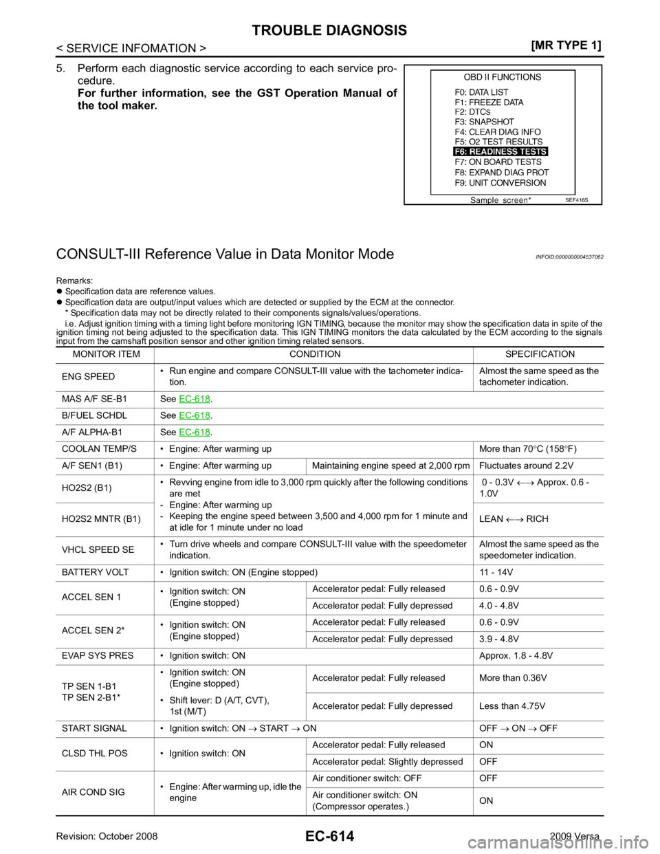
B/FUEL SCHDL See EC-618 .
A/F ALPHA-B1 See EC-618 .
COOLAN TEMP/S • Engine: After warming up More than 70 °C (158 °F)
A/F SEN1 (B1) • Engine: After warming up Maintaining engine speed at 2,000 rpm Fluctuates around 2.2V
HO2S2 (B1) • Revving engine from idle to 3,000 rpm quickly after the following conditions
are met
- Engine: After warming up
- Keeping the engine speed between 3,500 and 4,000 rpm for 1 minute and at idle for 1 minute under no load 0 - 0.3V
←→ Approx. 0.6 -
1.0V
HO2S2 MNTR (B1) LEAN ←→ RICH
VHCL SPEED SE • Turn drive wheels and compare CONSULT-III value with the speedometer
indication. Almost the same speed as the
speedometer indication.
BATTERY VOLT • Ignition switch: ON (Engine stopped) 11 - 14V
ACCEL SEN 1 • Ignition switch: ON
(Engine stopped) Accelerator pedal: Fully released 0.6 - 0.9V
Accelerator pedal: Fully depressed 4.0 - 4.8V
ACCEL SEN 2* • Ignition switch: ON
(Engine stopped) Accelerator pedal: Fully released 0.6 - 0.9V
Accelerator pedal: Fully depressed 3.9 - 4.8V
EVAP SYS PRES • Ignition switch: ON Approx. 1.8 - 4.8V
TP SEN 1-B1
TP SEN 2-B1* • Ignition switch: ON
(Engine stopped) Accelerator pedal: Fully released More than 0.36V
• Shift lever: D (A/T, CVT), 1st (M/T) Accelerator pedal: Fully depressed Less than 4.75V
START SIGNAL • Ignition switch: ON → START → ON OFF → ON → OFF
CLSD THL POS • Ignition switch: ON Accelerator
pedal: Fully released ON
Accelerator pedal: Slightly depressed OFF
AIR COND SIG • Engine: After warming up, idle the
engine Air conditioner switch: OFF OFF
Air conditioner switch: ON
(Compressor operates.) ON
Page 1971 of 4331

EC
NP
O
P/N POSI SW • Ignition switch: ON
Shift lever: P or N (A/T, CVT),
Neutral (M/T) ON
Shift lever: Except above OFF
PW/ST SIGNAL • Engine: After warming up, idle the
engine Steering wheel: Not being turned OFF
Steering wheel: Being turned ON
LOAD SIGNAL • Ignition switch: ON Rear window defogger switch: ON
and/or Lighting switch: 2nd ON
Rear window defogger switch and light-
ing switch: OFF OFF
IGNITION SW • Ignition switch: ON → OFF → ON ON → OFF → ON
HEATER FAN SW • Ignition switch: ON Heater fan: Operating ON
Heater fan: Not operating OFF
BRAKE SW • Ignition switch: ON Brake pedal: Fully released OFF
Brake pedal: Slightly depressed ON
INJ PULSE-B1 • Engine: After warming up
• Air conditioner switch: OFF
• Shift lever: P or N (A/T, CVT), Neutral (M/T)
• No load Idle 2.0 - 3.0 msec
2,000 rpm 1.9 - 2.9 msec
IGN TIMING • Engine: After warming up
• Air conditioner switch: OFF
• Shift lever: P or N (A/T, CVT), Neutral (M/T)
• No load Idle 8
° - 18 ° BTDC
2,000 rpm 25 ° - 45 ° BTDC
CAL/LD VALUE • Engine: After warming up
• Air conditioner switch: OFF
• Shift lever: P or N (A/T, CVT),
Neutral (M/T)
• No load Idle 10% - 35%
2,500 rpm 10% - 35%
MASS AIRFLOW • Engine: After warming up
• Air conditioner switch: OFF
• Shift lever: P or N (A/T, CVT), Neutral (M/T)
• No load Idle 1.0 - 4.0 g·m/s
2,500 rpm 2.0 - 10.0 g·m/s
PURG VOL C/V • Engine: After warming up
• Air conditioner switch: OFF
• Shift lever: P or N (A/T, CVT), Neutral (M/T)
• No load Idle
(Accelerator pedal is not depressed
even slightly, after engine starting) 0%
2,000 rpm 0 - 50%
INT/V TIM (B1) • Engine: After warming up
• Air conditioner switch: OFF
• Shift lever: P or N (A/T, CVT), Neutral (M/T)
• No load Idle
−5 ° - 5 °CA
When revving engine up to 2,000 rpm
quickly Approx. 0
° - 40 °CA
INT/V SOL (B1) • Engine: After warming up
• Air conditioner switch: OFF
• Shift lever: P or N (A/T, CVT),
Neutral (M/T)
• No load Idle 0% - 2%
When revving engine up to 2,000 rpm
quickly Approx. 0% - 90%
AIR COND RLY • Engine: After warming up, idle the
engine Air conditioner switch: OFF OFF
Air conditioner switch: ON
(Compressor operates) ON
FUEL PUMP RLY • For 1 second after turning ignition switch ON
• Engine running or cranking ON
• Except above conditions OFF
MONITOR ITEM CONDITION SPECIFICATION
Page 2043 of 4331
![NISSAN TIIDA 2009 Service Repair Manual DTC P0127 IAT SENSOR
EC-687
< SERVICE INFOMATION >
[MR TYPE 1] C
D E
F
G H
I
J
K L
M A EC
NP
O
DTC P0127 IAT SENSOR
Component Description INFOID:0000000004537157
The intake air temperature sensor](/manual-img/5/57398/w960_57398-2042.png "NISSAN TIIDA 2009 Service Repair Manual DTC P0127 IAT SENSOR
EC-687
< SERVICE INFOMATION >
[MR TYPE 1] C
D E
F
G H
I
J
K L
M A EC
NP
O
DTC P0127 IAT SENSOR
Component Description INFOID:0000000004537157
The intake air temperature sensor")
DTC P0127 IAT SENSOR
EC-687
< SERVICE INFOMATION >
[MR TYPE 1] C
D E
F
G H
I
J
K L
M A EC
NP
O
DTC P0127 IAT SENSOR
Component Description INFOID:0000000004537157
The intake air temperature sensor is built into mass air flow sensor
(1). The sensor detects intake air temperature and transmits a signal
to the ECM.
The temperature sensing unit uses a thermistor which is sensitive to
the change in temperature. Electric al resistance of the thermistor
decreases in response to the temperature rise.
*: This data is reference value and is measured between ECM terminal 46 (Intake air
temperature sensor) and ground.
CAUTION:
Do not use ECM ground terminals when measuring input/output
voltage. Doing so may result in damage to the ECM's transistor.
Use a ground other than ECM te rminals, such as the ground.
On Board Diagnosis Logic INFOID:0000000004537158
DTC Confirmation Procedure INFOID:0000000004537159
CAUTION:
Always drive vehicle at a safe speed.
NOTE:
If DTC Confirmation Procedure has been previously conduc ted, always turn ignition switch OFF and wait at
least 10 seconds before conducting the next test.
TESTING CONDITION:
This test may be conducted with the drive wheels lifted in the shop or by driving the vehicle. If a road
test is expected to be easier, it is unnecessary to lift the vehicle.
WITH CONSULT-III
1. Wait until engine coolant temperature is less than 90 °C (194 °F)
a. Turn ignition switch ON.
b. Select “DATA MONITOR” mode with CONSULT-III.
c. Check the engine coolant temperature.
d. If the engine coolant temperature is not less than 90 °C (194 °F), turn ignition switch OFF and cool down
engine.
• Perform the following steps before engine coolant temperature is above 90 °C (194 °F). PBIA9559J
Intake air temperature
°C ( °F) Voltage* V Resistance K.
Ω
25 (77) 3.3 1.800 - 2.200
80 (176) 1.2 0.283 - 0.359 SEF012P
DTC No. Trouble diagnosis name DTC detecting condition Possible cause
P0127
0127 Intake air temperature
too high Rationally incorrect voltage from the sensor is
sent to ECM, compared with the voltage signal
from engine coolant temperature sensor. • Harness or connectors
(Intake temperature sensor circuit is open
or shorted)
• Intake air temperature sensor
Page 2121 of 4331

EC
NP
O
DTC P0300 - P0304 MULTIPLE CYLINDER
MISFIRE, NO. 1 - 4 CYLINDER
MISFIRE
On Board Diagnosis Logic INFOID:0000000004537254
When a misfire occurs, engine speed will fluctuate. If the engine speed fluctuates enough to cause the crank-
shaft position (CKP) sensor (POS) signal to vary , ECM can determine that a misfire is occurring.
The misfire detection logic consists of the following two conditions.
1. One Trip Detection Logic (Three Way Catalyst Damage) On the 1st trip that a misfire condition occurs that can damage the three way catalyst (TWC) due to over-
heating, the MIL will blink.
When a misfire condition occurs, the ECM monitors the CKP sensor (POS) signal every 200 engine revo-
lutions for a change.
When the misfire condition decreases to a level t hat will not damage the TWC, the MIL will turn off.
If another misfire condition occurs that can damage the TWC on a second trip, the MIL will blink.
When the misfire condition decreases to a level t hat will not damage the TWC, the MIL will remain on.
If another misfire condition occurs that can damage the TWC, the MIL will begin to blink again.
2. Two Trip Detection Logic (Exhaust quality deterioration) For misfire conditions that will not damage the TWC (but will affect vehicle emissions), the MIL will only
light when the misfire is detected on a second trip. Du ring this condition, the ECM monitors the CKP sen-
sor signal every 1,000 engine revolutions.
A misfire malfunction can be detected on any one cylinder or on multiple cylinders.
DTC Confirmation Procedure INFOID:0000000004537255
CAUTION:
Always drive vehicle in safe manner according to traf fic conditions and obey all traffic laws when driv-
ing.
NOTE:
If DTC Confirmation Procedure has been previously conduc ted, always turn ignition switch OFF and wait at
least 10 seconds before conducting the next test.
1. Start engine and warm it up to normal operating temperature.
2. Turn ignition switch OFF and wait at least 10 seconds.
3. Restart engine and let it idle for about 15 minutes.
4. Check 1st trip DTC.
5. If 1st trip DTC is detected, go to EC-766, " Diagnosis Procedure " .
NOTE:
If 1st trip DTC is not detected during above proc edure, performing the following procedure is advised.
a. Turn ignition switch OFF and wait at least 10 seconds.
b. Start engine and drive the vehicle under the similar conditi ons to (1st trip) Freeze Frame Data for a certain
time. Refer to table below. Sensor Input Signal to ECM ECM function
Crankshaft position sensor (POS) Engine speed On board diagnosis of misfire DTC No. Trouble diagnosis name DTC detecting condition Possible cause
P0300
0300 Multiple cylinder misfire
detected Multiple cylinder misfire.
• Improper spark plug
• Insufficient compression
• Incorrect fuel pressure
• Fuel injector circuit is open or shorted
• Fuel injector
• Intake air leak
• The ignition signal circuit is open or shorted
• Lack of fuel
• Drive plate or flywheel
• Air fuel ratio (A/F) sensor 1
• Incorrect PCV hose connection
P0301
0301 No.1 cylinder misfire de-
tected No. 1 cylinder misfires.
P0302
0302 No. 2 cylinder misfire
detected No. 2 cylinder misfires.
P0303
0303 No. 3 cylinder misfire
detected No. 3 cylinder misfires.
P0304
0304 No. 4 cylinder misfire
detected No. 4 cylinder misfires.
Page 2149 of 4331
![NISSAN TIIDA 2009 Service Repair Manual DTC P0441 EVAP CONTROL SYSTEM
EC-793
< SERVICE INFOMATION >
[MR TYPE 1] C
D E
F
G H
I
J
K L
M A EC
NP
O
1. Start engine and warm it up to normal operating temperature.
2. Turn ignition switch OFF and](/manual-img/5/57398/w960_57398-2148.png "NISSAN TIIDA 2009 Service Repair Manual DTC P0441 EVAP CONTROL SYSTEM
EC-793
< SERVICE INFOMATION >
[MR TYPE 1] C
D E
F
G H
I
J
K L
M A EC
NP
O
1. Start engine and warm it up to normal operating temperature.
2. Turn ignition switch OFF and")
DTC P0441 EVAP CONTROL SYSTEM
EC-793
< SERVICE INFOMATION >
[MR TYPE 1] C
D E
F
G H
I
J
K L
M A EC
NP
O
1. Start engine and warm it up to normal operating temperature.
2. Turn ignition switch OFF and wait at least 10 seconds.
3. Start engine and let it idle for at least 70 seconds.
4. Select “PURG FLOW P0441” of “EVAPORATIVE SYSTEM” in “DTC CONFIRMATION” mode with CON-
SULT-III.
5. Touch “START”.
If “COMPLETED” is displayed, go to step 7.
6. When the following conditions are met, “TESTING ” will be displayed on the CONSULT-III screen. Maintain
the conditions continuously until “TES TING” changes to “COMPLETED”. (It will take at least 35 seconds.)
If TESTING is not changed for a long time, retry from step 2.
7. Make sure that “OK” is displayed after touching “S ELF-DIAG RESULTS”. If “NG” is displayed, refer to EC-793, " Diagnosis Procedure " .
Overall Function Check INFOID:0000000004537287
Use this procedure to check the overall monitoring func tion of the EVAP control system purge flow monitoring.
During this check, a 1st trip DTC might not be confirmed.
WITH GST
1. Lift up drive wheels.
2. Start engine and warm it up to normal operating temperature.
3. Turn ignition switch OFF and wait at least 10 seconds.
4. Start engine and wait at least 70 seconds.
5. Set voltmeter probes to ECM te rminals 42 (EVAP control system
pressure sensor signal) and ground.
6. Check EVAP control system pressure sensor value at idle speed and note it.
7. Establish and maintain the following conditions for at least 1 minute.
8. Verify that EVAP contro l system pressure sensor value stays 0. 1V less than the value at idle speed (mea-
sured at step 6) for at least 1 second.
9. If NG, go to EC-793, " Diagnosis Procedure " .
Diagnosis Procedure INFOID:00000000045372881.
CHECK EVAP CANISTER
1. Turn ignition switch OFF.
2. Check EVAP canister for cracks.
OK or NG OK (With CONSULT-III)>>GO TO 2.
OK (Without CONSULT-III)>>GO TO 3.
NG >> Replace EVAP canister. 2.
CHECK PURGE FLOW
Shift lever Suitable position
VHCL SPEED SE 32 - 120 km/h (20 - 75 MPH)
ENG SPEED 500 - 3,800 rpm
B/FUEL SCHDL 1.0 - 10.0 msec
COOLAN TEMP/S More than 0 °C Air conditioner switch ON
Headlamp switch ON
Rear window defogger switch ON
Engine speed Approx. 3,000 rpm
Shift lever Any position other than P, N or R PBIB3313E