2009 NISSAN TIIDA electrical diagram
[x] Cancel search: electrical diagramPage 6 of 4331
AT
N
O P
CONTENTS
AUTOMATIC TRANSAXLE
SERVICE INFORMATION .. ..........................5
INDEX FOR DTC ............................................ .....5
Alphabetical Index ............................................... ......5
DTC No. Index .................................................... ......5
PRECAUTIONS .............................................. .....7
Precaution for Supplemental Restraint System
(SRS) "AIR BAG" and "SEAT BELT PRE-TEN-
SIONER" ............................................................. ......
7
Precaution Necessary fo r Steering Wheel Rota-
tion After Battery Disconnect ............................... ......
7
Precaution for On Board Diagnosis (OBD) System
of A/T and Engine ............................................... ......
8
Precaution ........................................................... ......8
Service Notice or Precaution ............................... ......9
PREPARATION .............................................. ....11
Special Service Tool ........................................... ....11
Commercial Service Tool .................................... ....14
A/T FLUID ....................................................... ....17
Checking A/T Fluid .............................................. ....17
Changing A/T Fluid ............................................. ....17
A/T Fluid Cooler Cleaning ................................... ....18
A/T CONTROL SYSTEM ................................ ....21
Cross-Sectional View ... ...........................................21
Shift Mechanism .................................................. ....22
TCM Function ...................................................... ....30
CAN Communication ........................................... ....31
Input/Output Signal of TCM ................................. ....31
Line Pressure Control .. ...........................................32
Shift Control ........................................................ ....33
Lock-up Control ................................................... ....34
Engine Brake Control (Ove rrun Clutch Control) ......35
Control Valve ....................................................... ....37
Centrifugal Cancel Mechanism ........................... ....37
ON BOARD DIAGNOSTIC (OBD) SYSTEM .. ....39
Introduction ......................................................... ....39
OBD-II Function for A/T System .......................... ....39 One or Two Trip Detection Logic of OBD-II .........
....39
OBD-II Diagnostic Trouble Code (DTC) .............. ....39
Malfunction Indicator Lamp (MIL) ............................41
TROUBLE DIAGNOSIS .................................... 42
DTC Inspection Priority Chart .............................. ....42
Fail-Safe .............................................................. ....42
How to Perform Trouble Diagnosis for Quick and
Accurate Repair ................................................... ....
43
A/T Electrical Parts Location ............................... ....49
Circuit Diagram .................................................... ....50
Inspections Before Trouble Diagnosis ................. ....51
Road Test ............................................................ ....55
Check Before Engine Is Started .......................... ....56
Check at Idle ........................................................ ....56
Cruise Test - Part 1 ............................................. ....58
Cruise Test - Part 2 ............................................. ....61
Cruise Test - Part 3 ............................................. ....62
Vehicle Speed at Which Gear Shifting Occurs .... ....64
Vehicle Speed at Which Lock-up Occurs/Releas-
es ......................................................................... ....
64
Symptom Chart .................................................... ....65
TCM Terminal and Refere nce Value .......................77
CONSULT-III Function (TRANSMISSION) .......... ....79
Diagnosis Procedure withou t CONSULT-III ............83
DTC U1000 CAN COMMUNICATION LINE ..... 88
Description ........................................................... ....88
On Board Diagnosis Logic ................................... ....88
Possible Cause .................................................... ....88
DTC Confirmation Procedure .............................. ....88
Wiring Diagram - AT - CAN ................................. ....89
Diagnosis Procedure ........................................... ....90
DTC P0705 PARK/NEUTRAL POSITION
(PNP) SWITCH .................................................. 91
Description ........................................................... ....91
CONSULT-III Reference Va lue in Data Monitor
Mode .................................................................... ....
91
On Board Diagnosis Logic ................................... ....91
Possible Cause .................................................... ....91
Page 945 of 4331
CVT
N
O P
CONTENTS
CVT
RE0F08A
SERVICE INFORMATION .. ..........................
9
INDEX FOR DTC ............................................ .....9
Alphabetical Index ............................................... ......9
DTC No. Index .................................................... ......9
PRECAUTIONS .............................................. ....11
Precaution for Supplemental Restraint System
(SRS) "AIR BAG" and "SEAT BELT PRE-TEN-
SIONER" ............................................................. ....
11
Precaution Necessary fo r Steering Wheel Rota-
tion After Battery Disconnect ............................... ....
11
Precaution for On Board Diagnosis (OBD) System
of CVT and Engine .............................................. ....
12
Service After Replacing TCM and Transaxle As-
sembly ................................................................. ....
12
Removal and Installation Procedure for CVT Unit
Connector ............................................................ ....
13
Precaution ........................................................... ....14
Service Notice or Precaution ............................... ....15
PREPARATION .............................................. ....16
Special Service Tool ........................................... ....16
Commercial Service Tool .................................... ....16
CVT FLUID ..................................................... ....17
Checking CVT Fluid ............................................ ....17
Changing CVT Fluid ............................................ ....18
CVT Fluid Cooler Cleanin g .....................................18
CVT SYSTEM ... .............................................. ....22
Cross-Sectional View - RE0F08A ....................... ....22
Control System .................................................... ....23
Hydraulic Control System ........................................24
TCM Function ...................................................... ....24
CAN Communication ........................................... ....25
Input/Output Signal of TCM ................................. ....26
Line Pressure and Secondary Pressure Control . ....26
Shift Control ........................................................ ....27
Lock-up and Select Control ................................. ....28 Control Valve .......................................................
....29
ON BOARD DIAGNOSTIC (OBD) SYSTEM .... 30
Introduction .......................................................... ....30
OBD-II Function for CVT System ........................ ....30
One or Two Trip Detection Logic of OBD-II ......... ....30
OBD-II Diagnostic Trouble Code (DTC) .............. ....30
Malfunction Indicator Lamp (MIL) ............................31
TROUBLE DIAGNOSIS .................................... 33
DTC Inspection Priority Chart .............................. ....33
Fail-Safe .............................................................. ....33
How to Perform Trouble Diagnosis for Quick and
Accurate Repair ................................................... ....
34
CVT Electrical Parts Location .............................. ....39
Circuit Diagram .................................................... ....40
Inspections before Trouble Diagnosis ................. ....40
Road Test ............................................................ ....44
Check before Engine Is Started ........................... ....45
Check at Idle ........................................................ ....45
Cruise Test .......................................................... ....47
Vehicle Speed When Shifting Gears ................... ....49
TCM Terminal and Refere nce Value .......................49
CONSULT-III Function (TRANSMISSION) .......... ....51
Diagnosis Procedure withou t CONSULT-III ............59
DTC U1000 CAN COMMUNICATION LINE ..... 60
Description ........................................................... ....60
On Board Diagnosis Logic ................................... ....60
Possible Cause .................................................... ....60
DTC Confirmation Procedure .............................. ....60
Wiring Diagram - CVT - CAN ............................... ....61
Diagnosis Procedure ........................................... ....62
DTC U1010 TRANSMISSION CONTROL
MODULE (CAN) ................................................ 63
Description ........................................................... ....63
On Board Diagnosis Logic ................................... ....63
Possible Cause .................................................... ....63
DTC Confirmation Procedure .............................. ....63
Diagnosis Procedure ........................................... ....63
Page 947 of 4331
CVT
N
O
P
N
Description ..........................................................
..
104
CONSULT-III Refe rence Value in Data Monitor
Mode ................................................................... ..
104
On Board Diagnosis Logic .................................. ..104
Possible Cause ................................................... ..104
DTC Confirmation Procedure .............................. ..104
Diagnosis Procedure ........................................... ..104
DTC P0776 PRESSURE CONTROL SOLE-
NOID B PERFORMANCE (SEC PRESSURE
SOLENOID VALVE) ....................................... ..106
Description .......................................................... ..106
CONSULT-III Refe rence Value in Data Monitor
Mode ................................................................... ..
106
On Board Diagnosis Logic .................................. ..106
Possible Cause ................................................... ..106
DTC Confirmation Procedure .............................. ..106
Diagnosis Procedure ........................................... ..106
DTC P0778 PRESSURE CONTROL SOLE-
NOID B ELECTRICAL (SEC PRESSURE SO-
LENOID VALVE) ............................................ ..
108
Description .......................................................... ..108
CONSULT-III Refe rence Value in Data Monitor
Mode ................................................................... ..
108
On Board Diagnosis Logic .................................. ..108
Possible Cause ................................................... ..108
DTC Confirmation Procedure .............................. ..108
Wiring Diagram - CVT - SECPSV .........................109
Diagnosis Procedure ........................................... ..110
Component Inspection ........................................ ..111
DTC P0840 TRANSMISSION FLUID PRES-
SURE SENSOR A CIRCUIT (SEC PRES-
SURE SENSOR) ............................................. ..
113
Description .......................................................... ..113
CONSULT-III Refe rence Value in Data Monitor
Mode ................................................................... ..
113
On Board Diagnosis Logic .................................. ..113
Possible Cause ................................................... ..113
DTC Confirmation Procedure .............................. ..113
Wiring Diagram - CVT - SECPS .......................... ..114
Diagnosis Procedure ........................................... ..115
DTC P0841 PRESSURE SENSOR FUNC-
TION ............................................................... ..
117
Description .......................................................... ..117
CONSULT-III Refe rence Value in Data Monitor
Mode ................................................................... ..
117
On Board Diagnosis Logic .................................. ..117
Possible Cause ................................................... ..117
DTC Confirmation Procedure .............................. ..117
Diagnosis Procedure ........................................... ..117
DTC P0845 TRANSMISSION FLUID PRES-
SURE SENSOR B CIRCUIT (PRI PRESSURE
SENSOR) ........................................................ ..119
Description .......................................................... ..119 CONSULT-III Reference Va
lue in Data Monitor
Mode .................................................................... ..
119
On Board Diagnosis Logic ................................... ..119
Possible Cause .................................................... ..119
DTC Confirmation Procedure .............................. ..119
Wiring Diagram - CVT - PRIPS ........................... ..120
Diagnosis Procedure ........................................... ..121
DTC P0868 SECONDARY PRESSURE
DOWN ............................................................. 123
Description ........................................................... ..123
CONSULT-III Reference Va lue in Data Monitor
Mode .................................................................... ..
123
On Board Diagnosis Logic ................................... ..123
Possible Cause .................................................... ..123
DTC Confirmation Procedure .............................. ..123
Diagnosis Procedure ........................................... ..123
DTC P1701 TRANSMISSION CONTROL
MODULE (POWER SUPPLY) ......................... 125
Description ........................................................... ..125
On Board Diagnosis Logic ................................... ..125
Possible Cause .................................................... ..125
DTC Confirmation Procedure .............................. ..125
Wiring Diagram - CVT - POWER ......................... ..126
Diagnosis Procedure ........................................... ..127
DTC P1705 THROTTLE POSITION SENSOR .129
Description ........................................................... ..129
CONSULT-III Reference Va lue in Data Monitor
Mode .................................................................... ..
129
On Board Diagnosis Logic ................................... ..129
Possible Cause .................................................... ..129
DTC Confirmation Procedure .............................. ..129
Diagnosis Procedure ........................................... ..129
DTC P1722 ESTM VEHICLE SPEED SIGNAL .131
Description ........................................................... ..131
CONSULT-III Reference Va lue in Data Monitor
Mode .................................................................... ..
131
On Board Diagnosis Logic ................................... ..131
Possible Cause .................................................... ..131
DTC Confirmation Procedure .............................. ..131
Diagnosis Procedure ........................................... ..131
DTC P1723 CVT SPEED SENSOR FUNC-
TION ................................................................ 133
Description ........................................................... ..133
On Board Diagnosis Logic ................................... ..133
Possible Cause .................................................... ..133
DTC Confirmation Procedure .............................. ..133
Diagnosis Procedure ........................................... ..133
DTC P1726 ELECTRIC THROTTLE CON-
TROL SYSTEM ............................................... 135
Description ........................................................... ..135
On Board Diagnosis Logic ................................... ..135
Possible Cause .................................................... ..135
DTC Confirmation Procedure .............................. ..135
Diagnosis Procedure ........................................... ..135
Page 949 of 4331
CVT
N
O
P
N
Precaution Necessary fo
r Steering Wheel Rota-
tion After Battery Disconnect ............................... ..
189
Precaution for On Board Diagnosis (OBD) System
of CVT and Engine .............................................. ..
190
Service After Replacing TCM and Transaxle As-
sembly ................................................................. ..
190
Removal and Installation Procedure for CVT Unit
Connector ............................................................ ..
191
Precaution ........................................................... ..192
Service Notice or Precaution ............................... ..193
PREPARATION .............................................. ..195
Special Service Tool ........................................... ..195
Commercial Service Tool .................................... ..195
CVT FLUID ..................................................... ..196
Checking CVT Fluid ............................................ ..196
Changing CVT Fluid ............................................ ..197
CVT Fluid Cooler Cleanin g ...................................197
CVT SYSTEM ... .............................................. ..201
Cross-Sectional View - RE0F08B ....................... ..201
Control System .................................................... ..202
Hydraulic Control System ......................................203
TCM Function ...................................................... ..203
CAN Communication ........................................... ..204
Input/Output Signal of TCM ................................. ..204
Line Pressure and Secondary Pressure Control . ..205
Shift Control ........................................................ ..205
Lock-up and Select Control ................................. ..207
Control Valve ....................................................... ..207
ON BOARD DIAGNOSTIC (OBD) SYSTEM .. ..209
Introduction ......................................................... ..209
OBD-II Function for CVT System ........................ ..209
One or Two Trip Detection Logic of OBD-II ........ ..209
OBD-II Diagnostic Trouble Code (DTC) .............. ..209
Malfunction Indicator Lamp (MIL) ........................ ..210
TROUBLE DIAGNOSIS ................................. ..212
DTC Inspection Priority Chart ............................. ..212
Fail-Safe .............................................................. ..212
How to Perform Trouble Diagnosis for Quick and
Accurate Repair ........... .........................................
213
CVT Electrical Parts Location ............................. ..218
Circuit Diagram ................................................... ..219
Inspections before Trouble Diagnosis ................. ..219
Road Test ............................................................ ..223
Check before Engine Is Started ............................224
Check at Idle ....................................................... ..224
Cruise Test .......................................................... ..226
Vehicle Speed When Shifting Gears ................... ..228
TCM Terminal and Reference Value ................... ..228
CONSULT-III Function (TRANSMISSION) ......... ..230
Diagnosis Procedu re without CONSULT-III ........ ..237
DTC U1000 CAN COMMUNICATION LINE ... ..238
Description .......................................................... ..238
On Board Diagnosis Logic .................................. ..238
Possible Cause ................................................... ..238 DTC Confirmation Procedure ..............................
..238
Wiring Diagram - CVT - CAN ............................... ..239
Diagnosis Procedure ........................................... ..240
DTC U1010 TRANSMISSION CONTROL
MODULE (CAN) .............................................. 241
Description ........................................................... ..241
On Board Diagnosis Logic ................................... ..241
Possible Cause .................................................... ..241
DTC Confirmation Procedure .............................. ..241
Diagnosis Procedure ........................................... ..241
DTC P0703 STOP LAMP SWITCH CIRCUIT . 242
Description ........................................................... ..242
CONSULT-III Reference Va lue in Data Monitor
Mode .................................................................... ..
242
On Board Diagnosis Logic ................................... ..242
Possible Cause .................................................... ..242
DTC Confirmation Procedure .............................. ..242
Diagnosis Procedure ........................................... ..242
DTC P0705 PARK/NEUTRAL POSITION
SWITCH ........................................................... 244
Description ........................................................... ..244
CONSULT-III Reference Va lue in Data Monitor
Mode .................................................................... ..
244
On Board Diagnosis Logic ................................... ..244
Possible Cause .................................................... ..244
DTC Confirmation Procedure .............................. ..244
Wiring Diagram - CVT - PNP/SW ........................ ..245
Diagnosis Procedure ........................................... ..246
Component Inspection ......................................... ..247
DTC P0710 CVT FLUID TEMPERATURE
SENSOR CIRCUIT .......................................... 249
Description ........................................................... ..249
CONSULT-III Reference Va lue in Data Monitor
Mode .................................................................... ..
249
On Board Diagnosis Logic ................................... ..249
Possible Cause .................................................... ..249
DTC Confirmation Procedure .............................. ..249
Wiring Diagram - CVT - FTS ............................... ..250
Diagnosis Procedure ........................................... ..251
Component Inspection ......................................... ..252
DTC P0715 INPUT SPEED SENSOR CIR-
CUIT (PRI SPEED SENSOR) .......................... 254
Description ........................................................... ..254
CONSULT-III Reference Va lue in Data Monitor
Mode .................................................................... ..
254
On Board Diagnosis Logic ................................... ..254
Possible Cause .................................................... ..254
DTC Confirmation Procedure .............................. ..254
Wiring Diagram - CVT - PRSCVT ........................ ..255
Diagnosis Procedure ........................................... ..256
DTC P0720 VEHICLE SPEED SENSOR CVT
(SECONDARY SPEED SENSOR) .................. 258
Description ........................................................... ..258
Page 1227 of 4331
![NISSAN TIIDA 2009 Service Repair Manual DTC P0778 PRESSURE CONTROL SOLE
NOID B ELECTRICAL (SEC PRES-
SURE SOLENOID VALVE)
CVT-283
< SERVICE INFORMATION >
[RE0F08B] D
E
F
G H
I
J
K L
M A
B CVT
N
O P
Wiring Diagram - CVT - SECPSV
INFOID:00000 NISSAN TIIDA 2009 Service Repair Manual DTC P0778 PRESSURE CONTROL SOLE
NOID B ELECTRICAL (SEC PRES-
SURE SOLENOID VALVE)
CVT-283
< SERVICE INFORMATION >
[RE0F08B] D
E
F
G H
I
J
K L
M A
B CVT
N
O P
Wiring Diagram - CVT - SECPSV
INFOID:00000](/manual-img/5/57398/w960_57398-1226.png)
DTC P0778 PRESSURE CONTROL SOLE
NOID B ELECTRICAL (SEC PRES-
SURE SOLENOID VALVE)
CVT-283
< SERVICE INFORMATION >
[RE0F08B] D
E
F
G H
I
J
K L
M A
B CVT
N
O P
Wiring Diagram - CVT - SECPSV
INFOID:0000000004305707
TCM TERMINALS AND REFERENCE VALUES Refer to CVT-228, " TCM Terminal and Reference Value " . BCWA0676E
Page 1303 of 4331
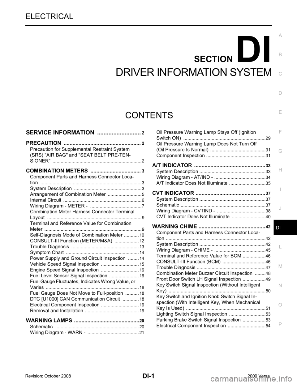
DI
N
O P
CONTENTS
DRIVER INFORMATION SYSTEM
SERVICE INFORMATION .. ..........................2
PRECAUTION ................................................ .....2
Precaution for Supplemental Restraint System
(SRS) "AIR BAG" and "SEAT BELT PRE-TEN-
SIONER" ............................................................. ......
2
COMBINATION METERS .............................. .....3
Component Parts and Harness Connector Loca-
tion ...................................................................... ......
3
System Description ............................................. ......3
Arrangement of Combination Meter .................... ......5
Internal Circuit ..................................................... ......6
Wiring Diagram - METER - ................................. ......7
Combination Meter Harness Connector Terminal
Layout ................................................................. ......
9
Terminal and Reference Value for Combination
Meter ................................................................... ......
9
Self-Diagnosis Mode of Combination Meter ........ ....10
CONSULT-III Function (METER/M&A) ............... ....12
Trouble Diagnosis ............................................... ....13
Symptom Chart ................................................... ....14
Power Supply and Ground Circuit Inspection ..... ....14
Vehicle Speed Signal Inspection ......................... ....15
Engine Speed Signal Inspection ......................... ....16
Fuel Level Sensor Signal Inspection ................... ....16
Fuel Gauge Fluctuates, Indicates Wrong Value, or
Varies .................................................................. ....
18
Fuel Gauge Does Not Move to Full-position ...........18
DTC [U1000] CAN Communication Circuit ......... ....18
Electrical Component Inspection ......................... ....19
Removal and Installation .........................................19
WARNING LAMPS ......................................... ....20
Schematic ........................................................... ....20
Wiring Diagram - WARN - ................................... ....21 Oil Pressure Wa
rning Lamp Stays Off (Ignition
Switch ON) .......................................................... ....
29
Oil Pressure Wa rning Lamp Does Not Turn Off
(Oil Pressure Is Normal) ...................................... ....
31
Component Inspection ......................................... ....31
A/T INDICATOR ................................................ 33
System Description .............................................. ....33
Wiring Diagram - AT/IND - ................................... ....34
A/T Indicator Does Not Illuminate ........................ ....35
CVT INDICATOR ............................................... 37
System Description .............................................. ....37
Schematic ............................................................ ....37
Wiring Diagram - CVTIND - ................................. ....38
CVT Indicator Does Not Illuminate ...................... ....40
WARNING CHIME ............................................. 42
Component Parts and Harness Connector Loca-
tion ....................................................................... ....
42
System Description .............................................. ....42
Wiring Diagram - CHIME - ................................... ....45
Terminal and Reference Value for BCM ..................46
CONSULT-III Function (B CM) .................................46
Trouble Diagnosis ................................................ ....47
Combination Meter Buzzer Cir cuit Inspection .........48
Front Door Switch LH Signal Inspection .............. ....49
Key Switch Signal Inspec tion (Without Intelligent
Key) ..................................................................... ....
50
Key Switch and Ignition Knob Switch Signal In-
spection (With Intelligent Key, When Mechanical
Key Is Used) ........................................................ ....
51
Lighting Switch Signal Inspection ........................ ....53
Parking Brake Switch Signal Inspection .............. ....53
Electrical Component Inspection ......................... ....54
Page 1369 of 4331
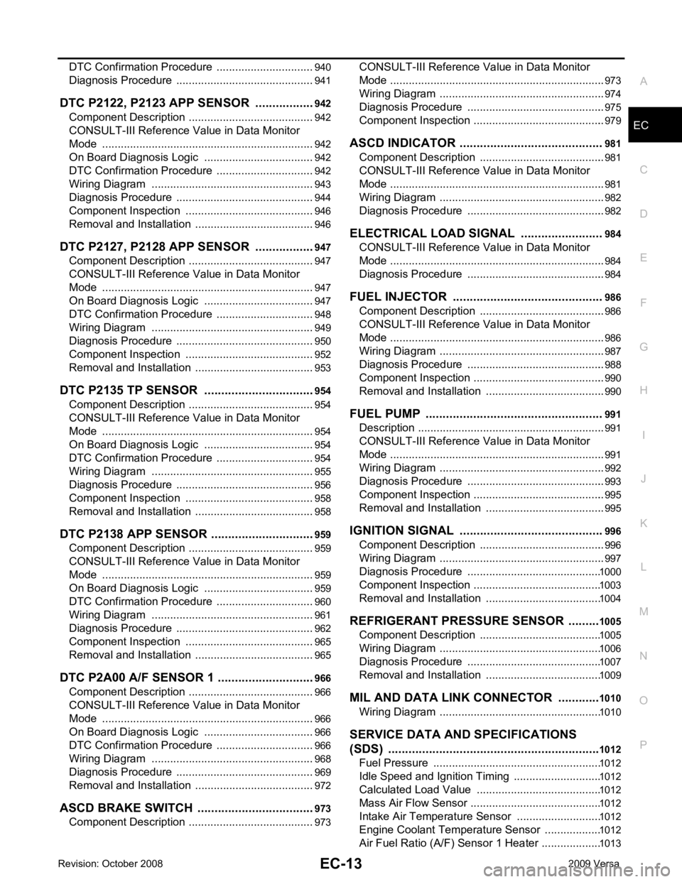
EC
A
N
O P
DTC Confirmation Procedure ..............................
..
940
Diagnosis Procedure ........................................... ..941
DTC P2122, P2123 APP SENSOR ................ ..942
Component Description ....................................... ..942
CONSULT-III Refe rence Value in Data Monitor
Mode ................................................................... ..
942
On Board Diagnosis Logic .................................. ..942
DTC Confirmation Procedure .............................. ..942
Wiring Diagram ................................................... ..943
Diagnosis Procedure ........................................... ..944
Component Inspection ........................................ ..946
Removal and Installation .......................................946
DTC P2127, P2128 APP SENSOR ................ ..947
Component Description ....................................... ..947
CONSULT-III Refe rence Value in Data Monitor
Mode ................................................................... ..
947
On Board Diagnosis Logic .................................. ..947
DTC Confirmation Procedure .............................. ..948
Wiring Diagram ................................................... ..949
Diagnosis Procedure ........................................... ..950
Component Inspection ........................................ ..952
Removal and Installation .......................................953
DTC P2135 TP SENSOR ............................... ..954
Component Description ....................................... ..954
CONSULT-III Refe rence Value in Data Monitor
Mode ................................................................... ..
954
On Board Diagnosis Logic .................................. ..954
DTC Confirmation Procedure .............................. ..954
Wiring Diagram ................................................... ..955
Diagnosis Procedure ........................................... ..956
Component Inspection ........................................ ..958
Removal and Installation .......................................958
DTC P2138 APP SENSOR ............................. ..959
Component Description ....................................... ..959
CONSULT-III Refe rence Value in Data Monitor
Mode ................................................................... ..
959
On Board Diagnosis Logic .................................. ..959
DTC Confirmation Procedure .............................. ..960
Wiring Diagram ................................................... ..961
Diagnosis Procedure ........................................... ..962
Component Inspection ........................................ ..965
Removal and Installation .......................................965
DTC P2A00 A/F SENSOR 1 ........................... ..966
Component Description ....................................... ..966
CONSULT-III Refe rence Value in Data Monitor
Mode ................................................................... ..
966
On Board Diagnosis Logic .................................. ..966
DTC Confirmation Procedure .............................. ..966
Wiring Diagram ................................................... ..968
Diagnosis Procedure ........................................... ..969
Removal and Installation .......................................972
ASCD BRAKE SWITCH ................................. ..973
Component Description ....................................... ..973 CONSULT-III Reference Va
lue in Data Monitor
Mode .................................................................... ..
973
Wiring Diagram .................................................... ..974
Diagnosis Procedure ........................................... ..975
Component Inspection ......................................... ..979
ASCD INDICATOR .......................................... 981
Component Description ....................................... ..981
CONSULT-III Reference Va lue in Data Monitor
Mode .................................................................... ..
981
Wiring Diagram .................................................... ..982
Diagnosis Procedure ........................................... ..982
ELECTRICAL LOAD SIGNAL ........................ 984
CONSULT-III Reference Va lue in Data Monitor
Mode .................................................................... ..
984
Diagnosis Procedure ........................................... ..984
FUEL INJECTOR ............................................ 986
Component Description ....................................... ..986
CONSULT-III Reference Va lue in Data Monitor
Mode .................................................................... ..
986
Wiring Diagram .................................................... ..987
Diagnosis Procedure ........................................... ..988
Component Inspection ......................................... ..990
Removal and Installation ..................................... ..990
FUEL PUMP .................................................... 991
Description ........................................................... ..991
CONSULT-III Reference Va lue in Data Monitor
Mode .................................................................... ..
991
Wiring Diagram .................................................... ..992
Diagnosis Procedure ........................................... ..993
Component Inspection ......................................... ..995
Removal and Installation ..................................... ..995
IGNITION SIGNAL .......................................... 996
Component Description ....................................... ..996
Wiring Diagram .................................................... ..997
Diagnosis Procedure ........................................... 1000
Component Inspection ......................................... 1003
Removal and Installation ..................................... 1004
REFRIGERANT PRESSURE SENSOR ......... 1005
Component Description ....................................... 1005
Wiring Diagram .................................................... 1006
Diagnosis Procedure ........................................... 1007
Removal and Installation ..................................... 1009
MIL AND DATA LINK CONNECTOR ............ 1010
Wiring Diagram .................................................... 1010
SERVICE DATA AND SPECIFICATIONS
(SDS) .............................................................. 1012
Fuel Pressure ...................................................... 1012
Idle Speed and Ignition Timing ............................ 1012
Calculated Load Value ........................................ 1012
Mass Air Flow Sensor .......................................... 1012
Intake Air Temperature Sensor ........................... 1012
Engine Coolant Temperature Sensor .................. 1012
Air Fuel Ratio (A/F) Sensor 1 Heater ................... 1013
Page 2145 of 4331
![NISSAN TIIDA 2009 Service Repair Manual DTC P0420 THREE WAY CATALYST FUNCTION
EC-789
< SERVICE INFOMATION >
[MR TYPE 1] C
D E
F
G H
I
J
K L
M A EC
NP
O
OK or NG OK >> GO TO 5.
NG >> Follow the EC-566, " Basic Inspection " .
5.
CHECK FUEL I NISSAN TIIDA 2009 Service Repair Manual DTC P0420 THREE WAY CATALYST FUNCTION
EC-789
< SERVICE INFOMATION >
[MR TYPE 1] C
D E
F
G H
I
J
K L
M A EC
NP
O
OK or NG OK >> GO TO 5.
NG >> Follow the EC-566, " Basic Inspection " .
5.
CHECK FUEL I](/manual-img/5/57398/w960_57398-2144.png)
DTC P0420 THREE WAY CATALYST FUNCTION
EC-789
< SERVICE INFOMATION >
[MR TYPE 1] C
D E
F
G H
I
J
K L
M A EC
NP
O
OK or NG OK >> GO TO 5.
NG >> Follow the EC-566, " Basic Inspection " .
5.
CHECK FUEL INJECTOR
1. Stop engine and turn ignition switch OFF.
2. Disconnect ECM harness connector.
3. Turn ignition switch ON.
4. Check voltage between ECM terminals 25, 29, 30, 31 and ground with CONSULT-III or tester.
Refer to Wiring Diagram for fuel injectors, EC-987, " Wiring Diagram " .
OK or NG OK >> GO TO 6.
NG >> Perform EC-988, " Diagnosis Procedure " .
6.
CHECK FUNCTION OF IGNITION COIL-I
CAUTION:
Do the following procedure in the place where ventilation is good without the combustible.
1. Turn ignition switch OFF.
2. Remove fuel pump (1) fuse in IPDM E/R (2) to release fuel pres-
sure.
NOTE:
Do not use CONSULT-III to release fuel pressure, or fuel pres-
sure applies again during the following procedure.
- : Vehicle front
3. Start engine.
4. After engine stalls, crank it two or three times to release all fuel pressure.
5. Turn ignition switch OFF.
6. Remove all ignition coil harness connectors to avoid the electri- cal discharge from the ignition coils.
7. Remove ignition coil and spark plug of the cylinder to be checked.
8. Crank engine for 5 seconds or more to remove combustion gas in the cylinder.
9. Connect spark plug and harness connector to ignition coil.
10. Fix ignition coil using a rope etc. with gap of 13 - 17 mm between the edge of the spark plug and grounded metal portion
as shown in the figure.
11. Crank engine for about 3 seconds, and check whether spark is
generated between the spark plug and the grounded metal por-
tion.
CAUTION:
• Do not approach to the spar k plug and the ignition coil
within 50cm. Be careful not to get an electrical shock
while checking, because the el ectrical discharge voltage
becomes 20kV or more. Items Specifications
Target idle speed A/T: 700
± 50 rpm (in P or N position)
CVT: 700 ± 50 rpm (in P or N position)
M/T: 700 ± 50 rpm (in Neutral position)
Ignition timing A/T: 13
± 5 ° BTDC (in P or N position)
CVT: 13 ± 5 ° BTDC (in P or N position)
M/T: 13 ± 5 ° BTDC (in Neutral position) Voltage: Battery voltage
Spark should be generated. PBIB2958E
PBIB2325E