2009 NISSAN TIIDA heater
[x] Cancel search: heaterPage 906 of 4331

Recommended Chemical Product and Sealant " .
2. If disconnected, reattach the upper radiator hose at the engine side.
3. Set the vehicle heater controls to the full HOT and heat er ON position. Turn the vehicle ignition ON with
the engine OFF as necessary to activate the heater mode.
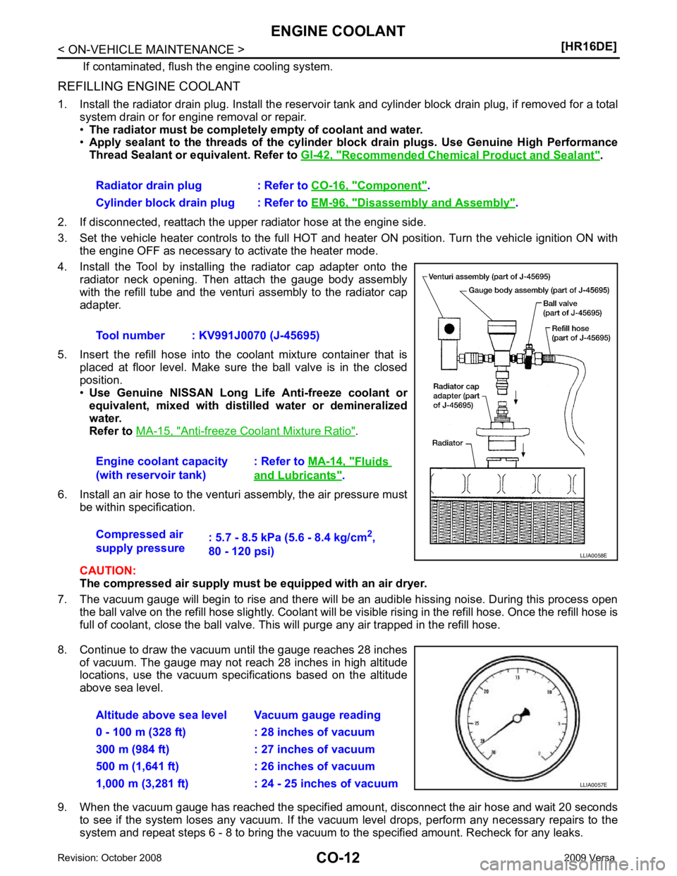
4. Install the Tool by installing the radiator cap adapter onto the radiator neck opening. Then attach the gauge body assembly
with the refill tube and the venturi assembly to the radiator cap
adapter.
5. Insert the refill hose into the coolant mixture container that is placed at floor level. Make sure the ball valve is in the closed
position.
• Use Genuine NISSAN Long Life Anti-freeze coolant or
equivalent, mixed with distil led water or demineralized
water.
Refer to MA-15, " Anti-freeze Coolant Mixture Ratio " .
6. Install an air hose to the venturi assembly, the air pressure must be within specification.
CAUTION:
The compressed air supply must be equipped with an air dryer.
7. The vacuum gauge will begin to rise and there will be an audible hissing noise. During this process open the ball valve on the refill hose slightly. Coolant will be vi sible rising in the refill hose. Once the refill hose is
full of coolant, close the ball valve. This will purge any air trapped in the refill hose.
8. Continue to draw the vacuum until the gauge reaches 28 inches of vacuum. The gauge may not reach 28 inches in high altitude
locations, use the vacuum specifications based on the altitude
above sea level.
9. When the vacuum gauge has reached the specifi ed amount, disconnect the air hose and wait 20 seconds
to see if the system loses any vacuum. If the vacuum level drops, perform any necessary repairs to the
system and repeat steps 6 - 8 to bring the vacuum to the specified amount. Recheck for any leaks.
Radiator drain plug : Refer to
CO-16, " Component " .
Cylinder block drain plug : Refer to EM-96, " Disassembly and Assembly " .
Tool number : KV991J0070 (J-45695)
Engine coolant capacity
(with reservoir tank) : Refer to
MA-14, " Fluids
and Lubricants " .
Compressed air
supply pressure : 5.7 - 8.5 kPa (5.6 - 8.4 kg/cm
2
,
80 - 120 psi)
Page 918 of 4331

Changing Engine Coolant " .
CAUTION:
• Perform this step when engine is cold.
• Never spill engine coolant on drive belt.
2. Disconnect radiator hose (upper). Refer to CO-16, " Component " .
3. Disconnect harness connector from engine coolant temperature sensor and block heater, if equipped.
4. Remove electric throttle control actuator water hoses.
5. Remove heater hoses.
6. Remove water outlet.
7. Remove engine coolant temperature sens or from water outlet, if necessary.
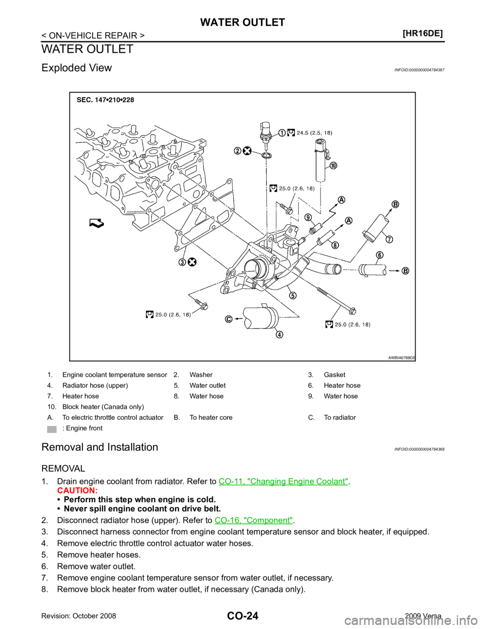
8. Remove block heater from water outlet, if necessary (Canada only). 1. Engine coolant temperature sensor 2. Washer 3. Gasket
4. Radiator hose (upper) 5. Water outlet 6. Heater hose
7. Heater hose 8. Water hose 9. Water hose
10. Block heater (Canada only)
A. To electric throttle control actuator B. To heater core C. To radiator : Engine front
Page 919 of 4331

CO
NP
O
INSTALLATION
Installation is in the reverse order of removal.
NOTE:
Insert the block heater into the water outlet until the clip is fully locked (Canada only).
Inspection INFOID:0000000004784369
INSPECTION AFTER INSTALLATION • Check that the reservoir tank cap is tightened.
• Check for leaks of engine coolant using suitable tool. Refer to CO-11, " Inspection " .
• Start and warm up the engine. Visually make sure that there is no leaks of engine coolant.
Page 930 of 4331
![NISSAN TIIDA 2009 Service Repair Manual CO-36< SERVICE INFORMATION >
[MR18DE]
ENGINE COOLANT
REFILLING ENGINE COOLANT
1. Install the radiator drain plug. Install the reservoir tank and cylinder block drain plug, if removed for a total
syst NISSAN TIIDA 2009 Service Repair Manual CO-36< SERVICE INFORMATION >
[MR18DE]
ENGINE COOLANT
REFILLING ENGINE COOLANT
1. Install the radiator drain plug. Install the reservoir tank and cylinder block drain plug, if removed for a total
syst](/manual-img/5/57398/w960_57398-929.png)
CO-36< SERVICE INFORMATION >
[MR18DE]
ENGINE COOLANT
REFILLING ENGINE COOLANT
1. Install the radiator drain plug. Install the reservoir tank and cylinder block drain plug, if removed for a total
system drain or for engine removal or repair.
• The radiator must be complete ly empty of coolant and water.
• Apply sealant to the threads of the cylinder bl ock drain plugs. Use Genuine High Performance
Thread Sealant or equivalent. Refer to GI-42, " Recommended Chemical Product and Sealant " .
2. If disconnected, reattach the upper radiator hose at the engine side.
3. Set the vehicle heater controls to the full HOT and heat er ON position. Turn the vehicle ignition ON with
the engine OFF as necessary to activate the heater mode.
4. Install the Tool by installing the radiator cap adapter onto the radiator neck opening. Then attach the gauge body assembly
with the refill tube and the venturi assembly to the radiator cap
adapter.
5. Insert the refill hose into the coolant mixture container that is placed at floor level. Make sure the ball valve is in the closed
position.
• Use Genuine NISSAN Long Life Anti-freeze coolant or
equivalent, mixed with distil led water or demineralized
water.
Refer to MA-15, " Anti-freeze Coolant Mixture Ratio " .
6. Install an air hose to the venturi assembly, the air pressure must be within specification.
CAUTION:
The compressed air supply must be equipped with an air dryer.
7. The vacuum gauge will begin to rise and there will be an audible hissing noise. During this process open the ball valve on the refill hose slightly. Coolant will be vi sible rising in the refill hose. Once the refill hose is
full of coolant, close the ball valve. This will purge any air trapped in the refill hose.
8. Continue to draw the vacuum until the gauge reaches 28 inches of vacuum. The gauge may not reach 28 inches in high altitude
locations, use the vacuum specifications based on the altitude
above sea level.
9. When the vacuum gauge has reached the specifi ed amount, disconnect the air hose and wait 20 seconds
to see if the system loses any vacuum. If the vacuum level drops, perform any necessary repairs to the
system and repeat steps 6 - 8 to bring the vacuum to the specified amount. Recheck for any leaks.
Radiator drain plug : Refer to
CO-38, " Component " .
Cylinder block drain plug : Refer to EM-200, " Disassembly and Assembly " .
Tool number : KV991J0070 (J-45695)
Engine coolant capacity
(with reservoir tank) : Refer to
MA-14, " Fluids
and Lubricants " .
Compressed air
supply pressure : 5.7 - 8.5 kPa (5.6 - 8.4 kg/cm
2
,
80 - 120 psi) LLIA0058E
Altitude above sea level Vacuum gauge reading
0 - 100 m (328 ft) : 28 inches of vacuum
300 m (984 ft) : 27 inches of vacuum
500 m (1,641 ft) : 26 inches of vacuum
1,000 m (3,281 ft) : 24 - 25 inches of vacuum LLIA0057E
Page 941 of 4331

CO
NP
O
WATER OUTLET AND WATER CONTROL VALVE
Component INFOID:0000000004305248
Removal and Installation INFOID:0000000004305249
REMOVAL 1. Drain engine coolant from radiator. Refer to CO-35, " Changing Engine Coolant " .
CAUTION:
• Perform this step when engine is cold.
• Never spill engine coolant on drive belt.
2. Remove air cleaner and air duct. Refer to EM-139, " Component " .
3. Remove radiator hose (lower) from engine. Refer to CO-38, " Component " .
4. Remove heater hoses and water hoses.
5. Remove water outlet.
6. Remove water control valve.
7. Remove engine coolant temperature sensor from the water outlet, if necessary. CAUTION:
• Handle carefully to avoid any shock to engine coolant temperature sensor.
• Replace the gasket with a new one.
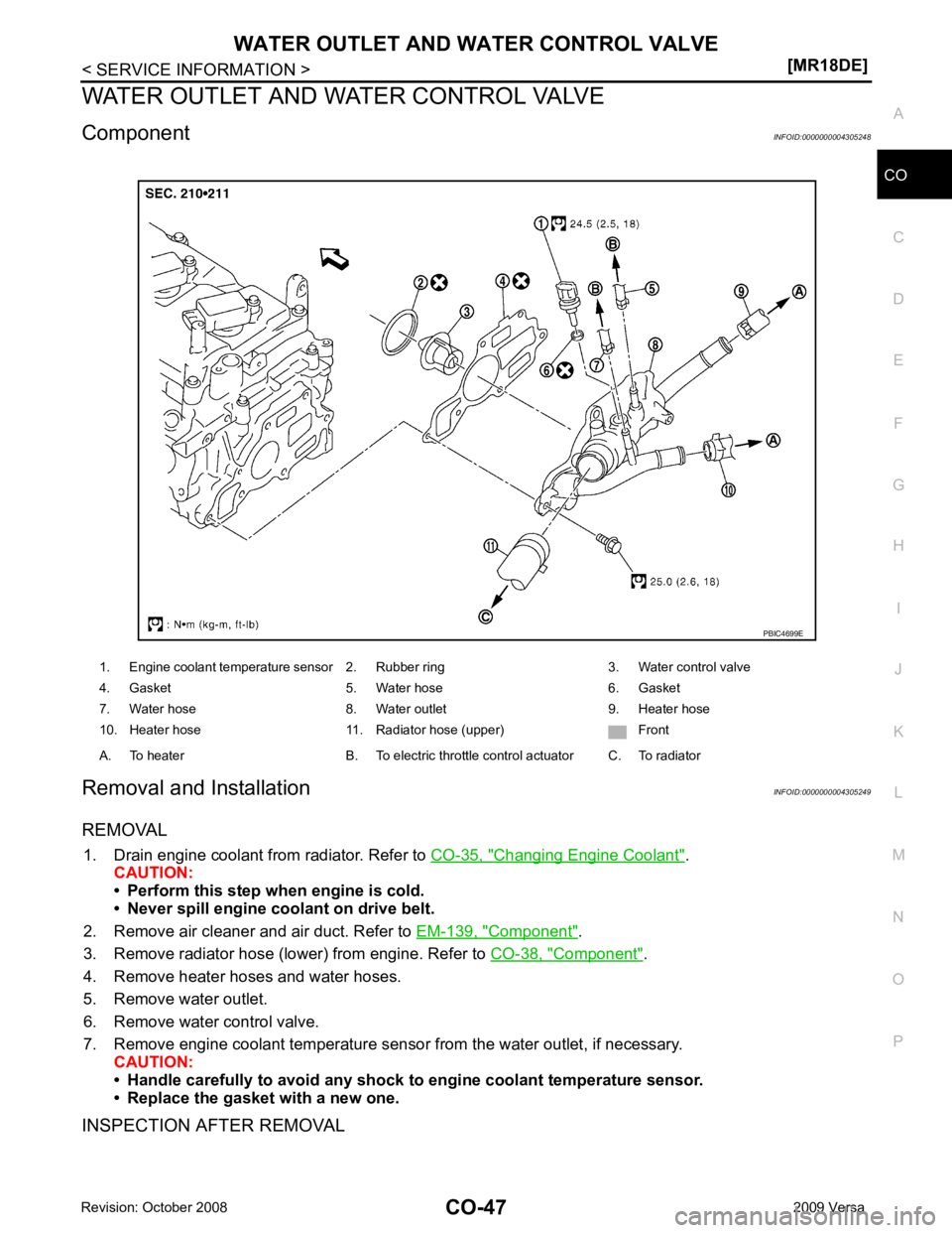
INSPECTION AFTER REMOVAL 1. Engine coolant temperature sensor 2. Rubber ring 3. Water control valve
4. Gasket 5. Water hose 6. Gasket
7. Water hose 8. Water outlet 9. Heater hose
10. Heater hose 11. Radiator hose (upper) Front
A. To heater B. To electric throttle control actuator C. To radiator
Page 1369 of 4331

EC
A
N
O P
DTC Confirmation Procedure ..............................
..
940
Diagnosis Procedure ........................................... ..941
DTC P2122, P2123 APP SENSOR ................ ..942
Component Description ....................................... ..942
CONSULT-III Refe rence Value in Data Monitor
Mode ................................................................... ..
942
On Board Diagnosis Logic .................................. ..942
DTC Confirmation Procedure .............................. ..942
Wiring Diagram ................................................... ..943
Diagnosis Procedure ........................................... ..944
Component Inspection ........................................ ..946
Removal and Installation .......................................946
DTC P2127, P2128 APP SENSOR ................ ..947
Component Description ....................................... ..947
CONSULT-III Refe rence Value in Data Monitor
Mode ................................................................... ..
947
On Board Diagnosis Logic .................................. ..947
DTC Confirmation Procedure .............................. ..948
Wiring Diagram ................................................... ..949
Diagnosis Procedure ........................................... ..950
Component Inspection ........................................ ..952
Removal and Installation .......................................953
DTC P2135 TP SENSOR ............................... ..954
Component Description ....................................... ..954
CONSULT-III Refe rence Value in Data Monitor
Mode ................................................................... ..
954
On Board Diagnosis Logic .................................. ..954
DTC Confirmation Procedure .............................. ..954
Wiring Diagram ................................................... ..955
Diagnosis Procedure ........................................... ..956
Component Inspection ........................................ ..958
Removal and Installation .......................................958
DTC P2138 APP SENSOR ............................. ..959
Component Description ....................................... ..959
CONSULT-III Refe rence Value in Data Monitor
Mode ................................................................... ..
959
On Board Diagnosis Logic .................................. ..959
DTC Confirmation Procedure .............................. ..960
Wiring Diagram ................................................... ..961
Diagnosis Procedure ........................................... ..962
Component Inspection ........................................ ..965
Removal and Installation .......................................965
DTC P2A00 A/F SENSOR 1 ........................... ..966
Component Description ....................................... ..966
CONSULT-III Refe rence Value in Data Monitor
Mode ................................................................... ..
966
On Board Diagnosis Logic .................................. ..966
DTC Confirmation Procedure .............................. ..966
Wiring Diagram ................................................... ..968
Diagnosis Procedure ........................................... ..969
Removal and Installation .......................................972
ASCD BRAKE SWITCH ................................. ..973
Component Description ....................................... ..973 CONSULT-III Reference Va
lue in Data Monitor
Mode .................................................................... ..
973
Wiring Diagram .................................................... ..974
Diagnosis Procedure ........................................... ..975
Component Inspection ......................................... ..979
ASCD INDICATOR .......................................... 981
Component Description ....................................... ..981
CONSULT-III Reference Va lue in Data Monitor
Mode .................................................................... ..
981
Wiring Diagram .................................................... ..982
Diagnosis Procedure ........................................... ..982
ELECTRICAL LOAD SIGNAL ........................ 984
CONSULT-III Reference Va lue in Data Monitor
Mode .................................................................... ..
984
Diagnosis Procedure ........................................... ..984
FUEL INJECTOR ............................................ 986
Component Description ....................................... ..986
CONSULT-III Reference Va lue in Data Monitor
Mode .................................................................... ..
986
Wiring Diagram .................................................... ..987
Diagnosis Procedure ........................................... ..988
Component Inspection ......................................... ..990
Removal and Installation ..................................... ..990
FUEL PUMP .................................................... 991
Description ........................................................... ..991
CONSULT-III Reference Va lue in Data Monitor
Mode .................................................................... ..
991
Wiring Diagram .................................................... ..992
Diagnosis Procedure ........................................... ..993
Component Inspection ......................................... ..995
Removal and Installation ..................................... ..995
IGNITION SIGNAL .......................................... 996
Component Description ....................................... ..996
Wiring Diagram .................................................... ..997
Diagnosis Procedure ........................................... 1000
Component Inspection ......................................... 1003
Removal and Installation ..................................... 1004
REFRIGERANT PRESSURE SENSOR ......... 1005
Component Description ....................................... 1005
Wiring Diagram .................................................... 1006
Diagnosis Procedure ........................................... 1007
Removal and Installation ..................................... 1009
MIL AND DATA LINK CONNECTOR ............ 1010
Wiring Diagram .................................................... 1010
SERVICE DATA AND SPECIFICATIONS
(SDS) .............................................................. 1012
Fuel Pressure ...................................................... 1012
Idle Speed and Ignition Timing ............................ 1012
Calculated Load Value ........................................ 1012
Mass Air Flow Sensor .......................................... 1012
Intake Air Temperature Sensor ........................... 1012
Engine Coolant Temperature Sensor .................. 1012
Air Fuel Ratio (A/F) Sensor 1 Heater ................... 1013
Page 1371 of 4331

EC
A
N
O P
Description ..........................................................
1138
Diagnosis Procedure ........................................... 1138
POWER SUPPLY AND GROUND CIRCUIT .. 1139
Wiring Diagram ................................................... 1139
Diagnosis Procedure ........................................... 1140
Ground Inspection ............................................... 1144
DTC U0101 CAN COMMUNICATION LINE ... 1145
Description .......................................................... 1145
On Board Diagnosis Logic .................................. 1145
DTC Confirmation Procedure .............................. 1145
Wiring Diagram ................................................... 1146
Diagnosis Procedure ........................................... 1146
DTC U0140 CAN COMMUNICATION LINE ... 1147
Description .......................................................... 1147
On Board Diagnosis Logic .................................. 1147
DTC Confirmation Procedure .............................. 1147
Wiring Diagram ................................................... 1148
Diagnosis Procedure ........................................... 1148
DTC U1001 CAN COMMUNICATION LINE ... 1149
Description .......................................................... 1149
On Board Diagnosis Logic .................................. 1149
DTC Confirmation Procedure .............................. 1149
Wiring Diagram ................................................... 1150
Diagnosis Procedure ........................................... 1150
DTC P0011 IVT CONTROL ............................ 1151
Description .......................................................... 1151
CONSULT-III Refe rence Value in Data Monitor
Mode ................................................................... 1151
On Board Diagnosis Logic .................................. 1152
DTC Confirmation Procedure .............................. 1152
Diagnosis Procedure ........................................... 1153
Component Inspection ........................................ 1154
Removal and Installation .....................................1154
DTC P0031, P0032 A/F SENSOR 1 HEATER 1155
Description .......................................................... 1155
CONSULT-III Refe rence Value in Data Monitor
Mode ................................................................... 1155
On Board Diagnosis Logic .................................. 1155
DTC Confirmation Procedure .............................. 1155
Wiring Diagram ................................................... 1156
Diagnosis Procedure ........................................... 1157
Component Inspection ........................................ 1158
Removal and Installation .....................................1159
DTC P0037, P0038 HO2S2 HEATER ............ 1160
Description .......................................................... 1160
CONSULT-III Refe rence Value in Data Monitor
Mode ................................................................... 1160
On Board Diagnosis Logic .................................. 1160
DTC Confirmation Procedure .............................. 1160
Wiring Diagram ................................................... 1161
Diagnosis Procedure ........................................... 1162
Component Inspection ........................................ 1164
Removal and Installation .....................................1164DTC P0075 IVT CONTROL SOLENOID
VALVE ............................................................ 1165
Component Description ....................................... 1165
CONSULT-III Reference Va lue in Data Monitor
Mode .................................................................... 1165
On Board Diagnosis Logic ................................... 1165
DTC Confirmation Procedure .............................. 1165
Wiring Diagram .................................................... 1166
Diagnosis Procedure ........................................... 1167
Component Inspection ......................................... 1168
Removal and Installation ..................................... 1169
DTC P0101 MAF SENSOR ............................ 1170
Component Description ....................................... 1170
CONSULT-III Reference Va lue in Data Monitor
Mode .................................................................... 1170
On Board Diagnosis Logic ................................... 1170
DTC Confirmation Procedure .............................. 1170
Overall Function Check ....................................... 1171
Wiring Diagram .................................................... 1173
Diagnosis Procedure ........................................... 1174
Component Inspection ......................................... 1176
Removal and Installation ..................................... 1177
DTC P0102, P0103 MAF SENSOR ................ 1178
Component Description ....................................... 1178
CONSULT-III Reference Va lue in Data Monitor
Mode .................................................................... 1178
On Board Diagnosis Logic ................................... 1178
DTC Confirmation Procedure .............................. 1178
Wiring Diagram .................................................... 1180
Diagnosis Procedure ........................................... 1181
Component Inspection ......................................... 1183
Removal and Installation ..................................... 1184
DTC P0112, P0113 IAT SENSOR .................. 1185
Component Description ....................................... 1185
On Board Diagnosis Logic ................................... 1185
DTC Confirmation Procedure .............................. 1185
Wiring Diagram .................................................... 1186
Diagnosis Procedure ........................................... 1186
Component Inspection ......................................... 1188
Removal and Installation ..................................... 1188
DTC P0116 ECT SENSOR ............................. 1189
Component Description ....................................... 1189
On Board Diagnosis Logic ................................... 1189
DTC Confirmation Procedure .............................. 1189
Diagnosis Procedure ........................................... 1190
Component Inspection ......................................... 1190
Removal and Installation ..................................... 1191
DTC P0117, P0118 ECT SENSOR ................ 1192
Component Description ....................................... 1192
On Board Diagnosis Logic ................................... 1192
DTC Confirmation Procedure .............................. 1193
Wiring Diagram .................................................... 1194
Diagnosis Procedure ........................................... 1194
Component Inspection ......................................... 1196
Removal and Installation ..................................... 1196
Page 1377 of 4331

EC
A
N
O P
SERVICE DATA AND SPECIFICATIONS
(SDS) .............................................................. 1534
Fuel Pressure ...................................................... 1534
Idle Speed and Ignition Timing ............................ 1534
Calculated Load Value ........................................ 1534
Mass Air Flow Sensor ......................................... 1534
Intake Air Temperature Sensor ........................... 1534
Engine Coolant Temperature Sensor .................. 1534Air Fuel Ratio (A/F) Sensor 1 Heater ...................
1535
Heated Oxygen sensor 2 Heater ......................... 1535
Crankshaft Position Sensor (POS) ...................... 1535
Camshaft Position Sensor (PHASE) ................... 1535
Throttle Control Motor .......................................... 1535
Fuel Injector ......................................................... 1535
Fuel Pump ........................................................... 1535