2009 NISSAN TIIDA wheel
[x] Cancel search: wheelPage 873 of 4331

BRC
N
O P
• When installing front wheel sensor, press rubber gr
ommets of strut bracket and body all the way in
until they get locked, and be careful not to apply a twist to harness. Harness should not be twisted
after installation. (Install it with harness paint ma rk on body side grommet facing front of vehicle,
and the strut side grommet facing outside of vehicle.)
REAR WHEEL SENSOR
Removal CAUTION:
• As much as possible, avoid rotati ng wheel sensor when removing it. Pull wheel sensors out without
pulling on sensor harness.
• Take care to avoid damaging wheel sensor edges or rotor teeth. Remove wheel sensor first before
removing front or rear wheel hub. This is to avo id damage to wheel sensor wiring and loss of sensor
function.
1. Disconnect the rear wheel sensor connector.
2. Remove the rear wheel sensor.
Installation Installation is in the reverse order of removal.
CAUTION:
• When installing, make sure there is no foreign mate rial such as iron chips on and in the mounting
hole of the wheel sensor. Make sure no foreign material has been caught in the sensor rotor. Remove
any foreign material and clean the mount.
• When installing rear wheel sensor, press rubber grommets of suspension arm bracket and harness
of side member all the way in until they get locked , and be careful not to apply a twist to harness.
Harness should not be twisted after installati on. (Aim the paint mark upward of vehicle.)
Page 875 of 4331
BRC
N
O P
ACTUATOR AND ELECTRIC UNIT (ASSEMBLY)
Removal and Installation INFOID:0000000004307283
CAUTION:
• Before servicing, disconnect battery negative terminal.
• To remove brake tube, use flare nut wrench to pr event flare nuts and brake tube from being dam-
aged. To install, use flare nut torque wrench, ti ghten flare nut to the specified torque. Refer to BR-11," Hydraulic Circuit " .
• Do not apply excessive impact to ABS actuator and elect ric unit (control unit), such as dropping it.
• Do not remove and install actuator by holding harness.
• After work is completed, bleed the air from the brake hydraulic system. Refer to BR-9, " Bleeding
Brake System " .
REMOVAL 1. Disconnect the battery negative terminal.
2. Remove the cowl top. Refer to EI-22, " Removal and Installation " .
3. Disconnect ABS actuator and electric unit (control unit) connector.
4. Loosen brake tube flare nuts, then remove brake tubes from ABS actuator and electric unit (control unit).
5. Remove brake booster hose from engine. Refer to BR-23, " Removal and Installation " .
6. Remove ABS actuator and electric unit (control unit) bracket bolts.
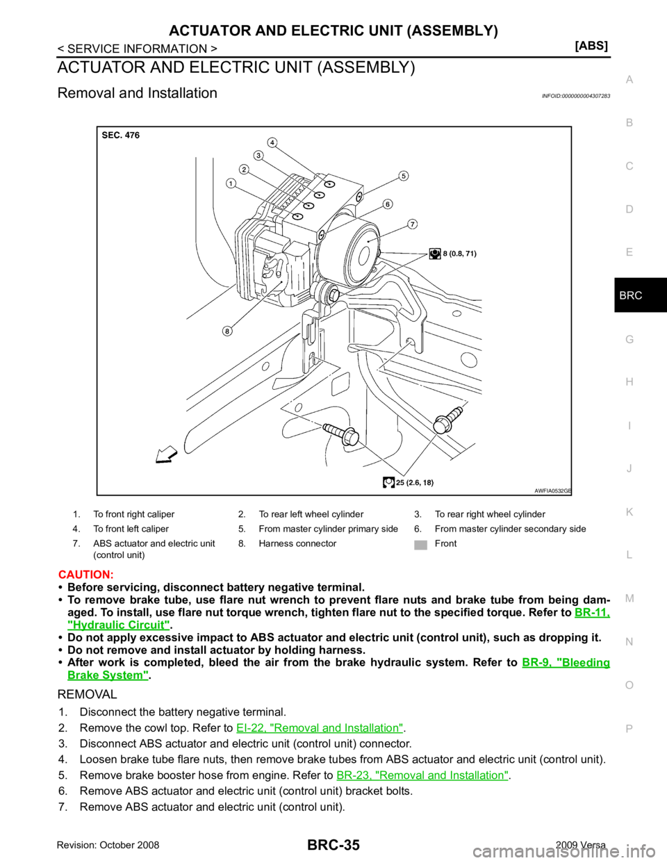
7. Remove ABS actuator and electric unit (control unit). 1. To front right caliper 2. To rear left wheel cylinder 3. To rear right wheel cylinder
4. To front left caliper 5. From master cylinder primary side 6. From master cylinder secondary side
7. ABS actuator and electric unit (control unit) 8. Harness connector Front
Page 877 of 4331

CL
N
O P
CONTENTS
CLUTCH
SERVICE INFORMATION .. ..........................2
PRECAUTIONS .............................................. .....2
Precaution for Supplemental Restraint System
(SRS) "AIR BAG" and "SEAT BELT PRE-TEN-
SIONER" ............................................................. ......
2
Precaution for Procedure without Cowl Top Cover ......2
Service Notice or Precaution ............................... ......2
PREPARATION .............................................. .....3
Special Service Tool ........................................... ......3
Commercial Service Tool .................................... ......3
NOISE, VIBRATION AND HARSHNESS
(NVH) TROUBLESHOOTING ........................ .....4
NVH Troubleshooting Chart ................................ ......4
CLUTCH PEDAL ............................................ .....5
On-vehicle Inspection and Adjustment ................ ......5
Removal and Installation ...........................................6
CLUTCH FLUID .............................................. .....8 Air Bleeding Procedure ........................................
.....8
CLUTCH MASTER CYLINDER ........................ 10
Removal and Installation ..................................... ....10
CSC (CONCENTRIC SLAVE CYLINDER) ....... 12
Exploded View ..................................................... ....12
Removal and Installation ..................................... ....12
CLUTCH PIPING ............................................... 14
Removal and Installation ..................................... ....14
CLUTCH DISC, CLUTCH COVER AND FLY-
WHEEL .............................................................. 15
Removal and Installation ..................................... ....15
SERVICE DATA AND SPECIFICATIONS
(SDS) ................................................................. 18
Clutch Control System ......................................... ....18
Clutch Pedal ........................................................ ....18
Clutch Disc .......................................................... ....18
Clutch Cover ........................................................ ....18
Page 880 of 4331

CL-8EM-195CL-12CL-15EM-216SUSPECTED PARTS (Possible cause)
CLUTCH PEDAL (Inspection and adjustment)
CLUTCH LINE (Air in line)
ENGINE MOUNTING (Loose)
CSC (Concentric slave cylinder) (Worn, dirty or damaged)
CLUTCH DISC (Out of true)
CLUTCH DISC (Runou t is excessive)
CLUTCH DISC (Lining broken)
CLUTCH DISC (Dirty or burned)
CLUTCH DISC (Oily)
CLUTCH DISC (Worn out)
CLUTCH DISC (Hardened)
CLUTCH DISC (Lack of spline grease)
DIAPHRAGM SPRING (Damaged)
DIAPHRAGM SPRING (Out of tip alignment)
PRESSURE PLATE (Distortion)
FLYWHEEL (Distortion)
Symptom Clutch grabs/chatters 1 2 2 2 2 2
Clutch pedal spongy 1
Clutch noisy 1
Clutch slips 1 2 2 3 4 5
Clutch does not disengage 1 2 5 5 5 5 5 5 6 6 7
Page 891 of 4331
CL
N
O P
CLUTCH DISC, CLUTCH COVER AND FLYWHEEL
Removal and Installation INFOID:0000000004305174
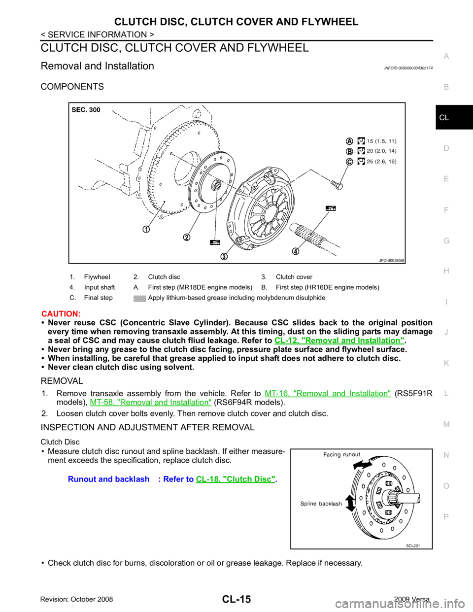
COMPONENTS
CAUTION:
• Never reuse CSC (Concentric Slave Cylinder). B ecause CSC slides back to the original position
every time when removing transaxle assembly. At th is timing, dust on the sliding parts may damage
a seal of CSC and may cause clut ch fliud leakage. Refer to CL-12, " Removal and Installation " .
• Never bring any grease to the clutch disc faci ng, pressure plate surface and flywheel surface.
• When installing, be careful that grease applied to input shaft does not adhere to clutch disc.
• Never clean clutch disc using solvent.
REMOVAL 1. Remove transaxle assembly from the vehicle. Refer to MT-16, " Removal and Installation " (RS5F91R
models), MT-58, " Removal and Installation " (RS6F94R models).
2. Loosen clutch cover bolts evenly. Then remove clutch cover and clutch disc.
INSPECTION AND ADJUSTMENT AFTER REMOVAL
Clutch Disc • Measure clutch disc runout and spline backlash. If either measure- ment exceeds the specificat ion, replace clutch disc.
• Check clutch disc for burns, discoloration or oil or grease leakage. Replace if necessary.
1. Flywheel 2. Clutch disc 3. Clutch cover
4. Input shaft A. First step (MR18DE engine models) B. First step (HR16DE engine models)
C. Final step Apply lithium-based grease including molybdenum disulphide Clutch Disc " .
Page 892 of 4331
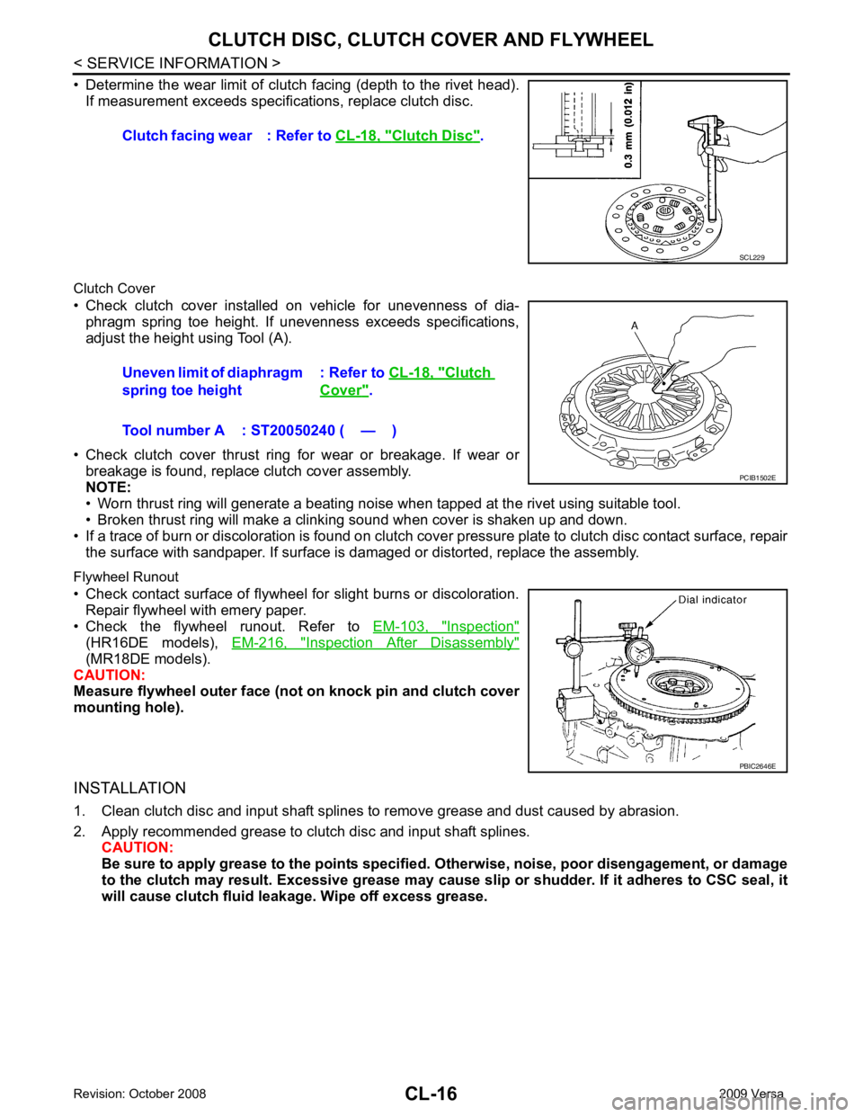
Inspection "
(HR16DE models),
EM-216, " Inspection After Disassembly "
(MR18DE models).
CAUTION:
Measure flywheel outer face (not on knock pin and clutch cover
mounting hole).
INSTALLATION
1. Clean clutch disc and input shaft splines to remove grease and dust caused by abrasion.
2. Apply recommended grease to clutch disc and input shaft splines. CAUTION:
Be sure to apply grease to the points specified. Ot herwise, noise, poor disengagement, or damage
to the clutch may result. Excessive grease may cause sl ip or shudder. If it adheres to CSC seal, it
will cause clutch fluid l eakage. Wipe off excess grease.
Clutch facing wear : Refer to
CL-18, " Clutch Disc " .
Clutch
Cover " .
Tool number A : ST20050240 ( — )
Page 895 of 4331

CO
N
O P
CONTENTS
ENGINE COOLING SYSTEM
HR16DE
PRECAUTION ....... ........................................
3
PRECAUTIONS .............................................. .....3
Precaution for Supplemental Restraint System
(SRS) "AIR BAG" and "SEAT BELT PRE-TEN-
SIONER" ............................................................. ......
3
Precaution Necessary fo r Steering Wheel Rota-
tion After Battery Disconnect ............................... ......
3
Precaution for Liquid Gasket ............................... ......4
PREPARATION .... ........................................5
PREPARATION .............................................. .....5
Special Service Tool ........................................... ......5
Commercial Service Tool .................................... ......5
SYMPTOM DIAGNOSIS ..... ..........................7
OVERHEATING CAUSE ANALYSIS ............. .....7
Troubleshooting Chart ..... ..........................................7
FUNCTION DIAGNOSIS .. .............................9
DESCRIPTION ............................................... .....9
Engine Cooling System ....................................... ......9
Engine Cooling System Schematic ..................... ....10
ON-VEHICLE MAINTENA NCE ....................11
ENGINE COOLANT ....................................... ....11
Inspection ............................................................ ....11
Changing Engine Coolant ................................... ....11
RADIATOR ..................................................... ....14
Checking Radiator Cap ....................................... ....14
Checking Radiator ............................................... ....14
ON-VEHICLE REPAIR .... .............................16
RADIATOR ..................................................... ....16 Component ..........................................................
....16
Removal and Installation ..................................... ....16
COOLING FAN .................................................. 18
Component (Models with A/C) ............................. ....18
Component (Models without A/C) ........................ ....18
Removal and Installation ..................................... ....19
WATER PUMP .................................................. 20
Exploded View ..................................................... ....20
Removal and Installation ..................................... ....20
Inspection ............................................................ ....21
THERMOSTAT .................................................. 22
Exploded View ..................................................... ....22
Removal and Installation ..................................... ....22
Inspection ............................................................ ....23
WATER OUTLET .............................................. 24
Exploded View ..................................................... ....24
Removal and Installation ..................................... ....24
Inspection ............................................................ ....25
DISASSEMBLY AND AS SEMBLY ..............26
COOLING FAN .................................................. 26
Disassembly and Assembly ................................. ....26
SERVICE DATA AND SPECIFICATIONS
(SDS) ............... .............................................
27
SERVICE DATA AND SPECIFICATIONS
(SDS) ................................................................. 27
Periodical Maintenance Specification .................. ....27
Radiator ............................................................... ....27
Thermostat .......................................................... ....27
MR18DE
SERVICE INFORMATION .. .........................28
PRECAUTIONS ................................................. 28
Page 897 of 4331

CO
NP
O
PRECAUTION
PRECAUTIONS
Precaution for Supplemental Restraint System (SRS) "AIR BAG" and "SEAT BELT
PRE-TENSIONER" INFOID:0000000004784387
The Supplemental Restraint System such as “A IR BAG” and “SEAT BELT PRE-TENSIONER”, used along
with a front seat belt, helps to reduce the risk or severi ty of injury to the driver and front passenger for certain
types of collision. This system includes seat belt switch inputs and dual stage front air bag modules. The SRS
system uses the seat belt switches to determine the front air bag deployment, and may only deploy one front
air bag, depending on the severity of a collision and w hether the front occupants are belted or unbelted.
Information necessary to service the system safely is included in the SRS and SB section of this Service Man-
ual.
WARNING:
• To avoid rendering the SRS inoper ative, which could increase the risk of personal injury or death in
the event of a collision which would result in air bag inflation, all maintenance must be performed by
an authorized NISSAN/INFINITI dealer.
• Improper maintenance, including in correct removal and installation of the SRS can lead to personal
injury caused by unintentional act ivation of the system. For removal of Spiral Cable and Air Bag
Module, see the SRS section.
• Do not use electrical test equipm ent on any circuit related to the SRS unless instructed to in this
Service Manual. SRS wiring harnesses can be identi fied by yellow and/or orange harnesses or har-
ness connectors.
• When working near the Airbag Diagnosis Sensor Un it or other Airbag System sensors with the Igni-
tion ON or engine running, DO NOT use air or el ectric power tools or strike near the sensor(s) with a
hammer. Heavy vibration could activate the sensor( s) and deploy the air bag(s), possibly causing
serious injury.
• When using air or electric power tools or hammers , always switch the Ignition OFF, disconnect the
battery, and wait at least 3 minutes before performing any service.
Precaution Necessary for Steering Wh eel Rotation After Battery Disconnect
INFOID:0000000004784348
NOTE:
• This Procedure is applied only to models with Inte lligent Key system and NATS (NISSAN ANTI-THEFT SYS-
TEM).
• Remove and install all control units after disconnecti ng both battery cables with the ignition knob in the
″ LOCK ″ position.
• Always use CONSULT-III to perform self-diagnosis as a part of each function inspection after finishing work.
If DTC is detected, perform trouble diagnosis according to self-diagnostic results.
For models equipped with the Intelligent Key system and NATS , an electrically controlled steering lock mech-
anism is adopted on the key cylinder.
For this reason, if the battery is disconnected or if the battery is discharged, the steering wheel will lock and
steering wheel rotation will become impossible.
If steering wheel rotation is required when battery pow er is interrupted, follow the procedure below before
starting the repair operation.
OPERATION PROCEDURE 1. Connect both battery cables. NOTE:
Supply power using jumper cables if battery is discharged.
2. Use the Intelligent Key or mechanical key to turn the ignition switch to the ″ACC ″ position. At this time, the
steering lock will be released.
3. Disconnect both battery cables. The steering lock will remain released and the steering wheel can be
rotated.
4. Perform the necessary repair operation.
5. When the repair work is completed, return the ignition switch to the ″LOCK ″ position before connecting
the battery cables. (At this time, the steering lock mechanism will engage.)
6. Perform a self-diagnosis check of al l control units using CONSULT-III.