2009 NISSAN TIIDA wheel
[x] Cancel search: wheelPage 914 of 4331
Changing Engine Coolant " .
CAUTION:
• Perform this step when the engine is cold.
• Never spill engine coolant on drive belts.
2. Steer front wheel to the right.
3. Remove front fender protector (RH). Refer to EI-24, " Removal and Installation " .
4. Loosen mounting bolts of water pump pulley before loosening belt tension of drive belt.
5. Remove drive belt. Refer to EM-15, " Removal and Installation " .
6. Remove water pump pulley.
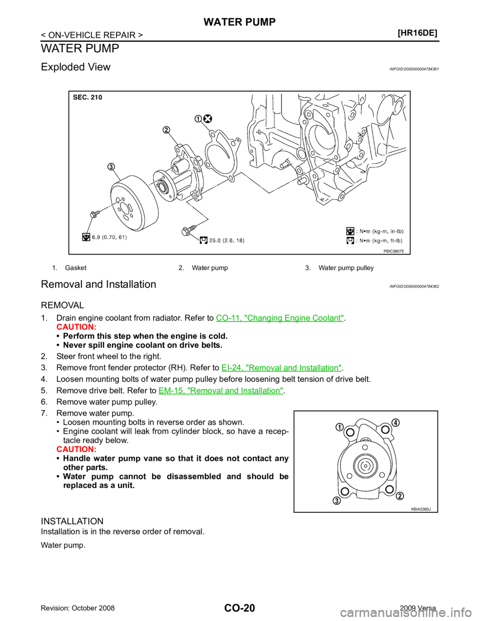
7. Remove water pump. • Loosen mounting bolts in reverse order as shown.
• Engine coolant will leak from cylinder block, so have a recep-
tacle ready below.
CAUTION:
• Handle water pump vane so that it does not contact any
other parts.
• Water pump cannot be disassembled and should be replaced as a unit.
INSTALLATION
Installation is in the reverse order of removal.
Water pump. 1. Gasket 2. Water pump 3. Water pump pulley
KBIA3393J
Page 927 of 4331

CO
NP
O
Except cool-
ing system
parts mal-
function — Overload on engine
Abusive driving
High engine rpm under no
load
Driving in low gear for ex-
tended time
Driving at extremely high
speed
Power train system mal-
function
—
Installed improper size
wheels and tires
Dragging brakes
Improper ignition timing
Blocked or restricted air
flow Blocked bumper Installed front bumper fas-
cia cover
—
Blocked radiator grille Mud contamination or paper
clogging
Blocked radiator Blocked air flow
Blocked condenser
Installed large fog lamp
Symptom Check items
Page 945 of 4331

CVT
N
O P
CONTENTS
CVT
RE0F08A
SERVICE INFORMATION .. ..........................
9
INDEX FOR DTC ............................................ .....9
Alphabetical Index ............................................... ......9
DTC No. Index .................................................... ......9
PRECAUTIONS .............................................. ....11
Precaution for Supplemental Restraint System
(SRS) "AIR BAG" and "SEAT BELT PRE-TEN-
SIONER" ............................................................. ....
11
Precaution Necessary fo r Steering Wheel Rota-
tion After Battery Disconnect ............................... ....
11
Precaution for On Board Diagnosis (OBD) System
of CVT and Engine .............................................. ....
12
Service After Replacing TCM and Transaxle As-
sembly ................................................................. ....
12
Removal and Installation Procedure for CVT Unit
Connector ............................................................ ....
13
Precaution ........................................................... ....14
Service Notice or Precaution ............................... ....15
PREPARATION .............................................. ....16
Special Service Tool ........................................... ....16
Commercial Service Tool .................................... ....16
CVT FLUID ..................................................... ....17
Checking CVT Fluid ............................................ ....17
Changing CVT Fluid ............................................ ....18
CVT Fluid Cooler Cleanin g .....................................18
CVT SYSTEM ... .............................................. ....22
Cross-Sectional View - RE0F08A ....................... ....22
Control System .................................................... ....23
Hydraulic Control System ........................................24
TCM Function ...................................................... ....24
CAN Communication ........................................... ....25
Input/Output Signal of TCM ................................. ....26
Line Pressure and Secondary Pressure Control . ....26
Shift Control ........................................................ ....27
Lock-up and Select Control ................................. ....28 Control Valve .......................................................
....29
ON BOARD DIAGNOSTIC (OBD) SYSTEM .... 30
Introduction .......................................................... ....30
OBD-II Function for CVT System ........................ ....30
One or Two Trip Detection Logic of OBD-II ......... ....30
OBD-II Diagnostic Trouble Code (DTC) .............. ....30
Malfunction Indicator Lamp (MIL) ............................31
TROUBLE DIAGNOSIS .................................... 33
DTC Inspection Priority Chart .............................. ....33
Fail-Safe .............................................................. ....33
How to Perform Trouble Diagnosis for Quick and
Accurate Repair ................................................... ....
34
CVT Electrical Parts Location .............................. ....39
Circuit Diagram .................................................... ....40
Inspections before Trouble Diagnosis ................. ....40
Road Test ............................................................ ....44
Check before Engine Is Started ........................... ....45
Check at Idle ........................................................ ....45
Cruise Test .......................................................... ....47
Vehicle Speed When Shifting Gears ................... ....49
TCM Terminal and Refere nce Value .......................49
CONSULT-III Function (TRANSMISSION) .......... ....51
Diagnosis Procedure withou t CONSULT-III ............59
DTC U1000 CAN COMMUNICATION LINE ..... 60
Description ........................................................... ....60
On Board Diagnosis Logic ................................... ....60
Possible Cause .................................................... ....60
DTC Confirmation Procedure .............................. ....60
Wiring Diagram - CVT - CAN ............................... ....61
Diagnosis Procedure ........................................... ....62
DTC U1010 TRANSMISSION CONTROL
MODULE (CAN) ................................................ 63
Description ........................................................... ....63
On Board Diagnosis Logic ................................... ....63
Possible Cause .................................................... ....63
DTC Confirmation Procedure .............................. ....63
Diagnosis Procedure ........................................... ....63
Page 949 of 4331

CVT
N
O
P
N
Precaution Necessary fo
r Steering Wheel Rota-
tion After Battery Disconnect ............................... ..
189
Precaution for On Board Diagnosis (OBD) System
of CVT and Engine .............................................. ..
190
Service After Replacing TCM and Transaxle As-
sembly ................................................................. ..
190
Removal and Installation Procedure for CVT Unit
Connector ............................................................ ..
191
Precaution ........................................................... ..192
Service Notice or Precaution ............................... ..193
PREPARATION .............................................. ..195
Special Service Tool ........................................... ..195
Commercial Service Tool .................................... ..195
CVT FLUID ..................................................... ..196
Checking CVT Fluid ............................................ ..196
Changing CVT Fluid ............................................ ..197
CVT Fluid Cooler Cleanin g ...................................197
CVT SYSTEM ... .............................................. ..201
Cross-Sectional View - RE0F08B ....................... ..201
Control System .................................................... ..202
Hydraulic Control System ......................................203
TCM Function ...................................................... ..203
CAN Communication ........................................... ..204
Input/Output Signal of TCM ................................. ..204
Line Pressure and Secondary Pressure Control . ..205
Shift Control ........................................................ ..205
Lock-up and Select Control ................................. ..207
Control Valve ....................................................... ..207
ON BOARD DIAGNOSTIC (OBD) SYSTEM .. ..209
Introduction ......................................................... ..209
OBD-II Function for CVT System ........................ ..209
One or Two Trip Detection Logic of OBD-II ........ ..209
OBD-II Diagnostic Trouble Code (DTC) .............. ..209
Malfunction Indicator Lamp (MIL) ........................ ..210
TROUBLE DIAGNOSIS ................................. ..212
DTC Inspection Priority Chart ............................. ..212
Fail-Safe .............................................................. ..212
How to Perform Trouble Diagnosis for Quick and
Accurate Repair ........... .........................................
213
CVT Electrical Parts Location ............................. ..218
Circuit Diagram ................................................... ..219
Inspections before Trouble Diagnosis ................. ..219
Road Test ............................................................ ..223
Check before Engine Is Started ............................224
Check at Idle ....................................................... ..224
Cruise Test .......................................................... ..226
Vehicle Speed When Shifting Gears ................... ..228
TCM Terminal and Reference Value ................... ..228
CONSULT-III Function (TRANSMISSION) ......... ..230
Diagnosis Procedu re without CONSULT-III ........ ..237
DTC U1000 CAN COMMUNICATION LINE ... ..238
Description .......................................................... ..238
On Board Diagnosis Logic .................................. ..238
Possible Cause ................................................... ..238 DTC Confirmation Procedure ..............................
..238
Wiring Diagram - CVT - CAN ............................... ..239
Diagnosis Procedure ........................................... ..240
DTC U1010 TRANSMISSION CONTROL
MODULE (CAN) .............................................. 241
Description ........................................................... ..241
On Board Diagnosis Logic ................................... ..241
Possible Cause .................................................... ..241
DTC Confirmation Procedure .............................. ..241
Diagnosis Procedure ........................................... ..241
DTC P0703 STOP LAMP SWITCH CIRCUIT . 242
Description ........................................................... ..242
CONSULT-III Reference Va lue in Data Monitor
Mode .................................................................... ..
242
On Board Diagnosis Logic ................................... ..242
Possible Cause .................................................... ..242
DTC Confirmation Procedure .............................. ..242
Diagnosis Procedure ........................................... ..242
DTC P0705 PARK/NEUTRAL POSITION
SWITCH ........................................................... 244
Description ........................................................... ..244
CONSULT-III Reference Va lue in Data Monitor
Mode .................................................................... ..
244
On Board Diagnosis Logic ................................... ..244
Possible Cause .................................................... ..244
DTC Confirmation Procedure .............................. ..244
Wiring Diagram - CVT - PNP/SW ........................ ..245
Diagnosis Procedure ........................................... ..246
Component Inspection ......................................... ..247
DTC P0710 CVT FLUID TEMPERATURE
SENSOR CIRCUIT .......................................... 249
Description ........................................................... ..249
CONSULT-III Reference Va lue in Data Monitor
Mode .................................................................... ..
249
On Board Diagnosis Logic ................................... ..249
Possible Cause .................................................... ..249
DTC Confirmation Procedure .............................. ..249
Wiring Diagram - CVT - FTS ............................... ..250
Diagnosis Procedure ........................................... ..251
Component Inspection ......................................... ..252
DTC P0715 INPUT SPEED SENSOR CIR-
CUIT (PRI SPEED SENSOR) .......................... 254
Description ........................................................... ..254
CONSULT-III Reference Va lue in Data Monitor
Mode .................................................................... ..
254
On Board Diagnosis Logic ................................... ..254
Possible Cause .................................................... ..254
DTC Confirmation Procedure .............................. ..254
Wiring Diagram - CVT - PRSCVT ........................ ..255
Diagnosis Procedure ........................................... ..256
DTC P0720 VEHICLE SPEED SENSOR CVT
(SECONDARY SPEED SENSOR) .................. 258
Description ........................................................... ..258
Page 955 of 4331

CVT
N
O P
PRECAUTIONS
Precaution for Supplemental Restraint System (SRS) "AIR BAG" and "SEAT BELT
PRE-TENSIONER" INFOID:0000000004800719
The Supplemental Restraint System such as “A IR BAG” and “SEAT BELT PRE-TENSIONER”, used along
with a front seat belt, helps to reduce the risk or severi ty of injury to the driver and front passenger for certain
types of collision. This system includes seat belt switch inputs and dual stage front air bag modules. The SRS
system uses the seat belt switches to determine the front air bag deployment, and may only deploy one front
air bag, depending on the severity of a collision and w hether the front occupants are belted or unbelted.
Information necessary to service the system safely is included in the SRS and SB section of this Service Man-
ual.
WARNING:
• To avoid rendering the SRS inoper ative, which could increase the risk of personal injury or death in
the event of a collision which would result in air bag inflation, all maintenance must be performed by
an authorized NISSAN/INFINITI dealer.
• Improper maintenance, including in correct removal and installation of the SRS can lead to personal
injury caused by unintentional act ivation of the system. For removal of Spiral Cable and Air Bag
Module, see the SRS section.
• Do not use electrical test equipm ent on any circuit related to the SRS unless instructed to in this
Service Manual. SRS wiring harnesses can be identi fied by yellow and/or orange harnesses or har-
ness connectors.
• When working near the Airbag Diagnosis Sensor Un it or other Airbag System sensors with the Igni-
tion ON or engine running, DO NOT use air or el ectric power tools or strike near the sensor(s) with a
hammer. Heavy vibration could activate the sensor( s) and deploy the air bag(s), possibly causing
serious injury.
• When using air or electric power tools or hammers , always switch the Ignition OFF, disconnect the
battery, and wait at least 3 minutes before performing any service.
Precaution Necessary for Steering Wh eel Rotation After Battery Disconnect
INFOID:0000000004666854
NOTE:
• This Procedure is applied only to models with Intell igent Key system and NVIS/IVIS (NISSAN/INFINITI
VEHICLE IMMOBILIZER SYSTEM - NATS).
• Remove and install all control units after disconnecti ng both battery cables with the ignition knob in the
″ LOCK ″ position.
• Always use CONSULT-III to perform self-diagnosis as a part of each function inspection after finishing work.
If DTC is detected, perform trouble diagnosis according to self-diagnostic results.
For models equipped with the Intelligent Key system and NVIS/IVIS, an electrically controlled steering lock
mechanism is adopted on the key cylinder.
For this reason, if the battery is disconnected or if the battery is discharged, the steering wheel will lock and
steering wheel rotation will become impossible.
If steering wheel rotation is required when battery pow er is interrupted, follow the procedure below before
starting the repair operation.
OPERATION PROCEDURE 1. Connect both battery cables. NOTE:
Supply power using jumper cables if battery is discharged.
2. Use the Intelligent Key or mechanical key to turn the ignition switch to the ″ACC ″ position. At this time, the
steering lock will be released.
3. Disconnect both battery cables. The steering lock will remain released and the steering wheel can be
rotated.
4. Perform the necessary repair operation.
5. When the repair work is completed, return the ignition switch to the ″LOCK ″ position before connecting
the battery cables. (At this time, the steering lock mechanism will engage.)
6. Perform a self-diagnosis check of al l control units using CONSULT-III.
Page 1133 of 4331

CVT
N
O P
PRECAUTIONS
Precaution for Supplemental Restraint System (SRS) "AIR BAG" and "SEAT BELT
PRE-TENSIONER" INFOID:0000000004800720
The Supplemental Restraint System such as “A IR BAG” and “SEAT BELT PRE-TENSIONER”, used along
with a front seat belt, helps to reduce the risk or severi ty of injury to the driver and front passenger for certain
types of collision. This system includes seat belt switch inputs and dual stage front air bag modules. The SRS
system uses the seat belt switches to determine the front air bag deployment, and may only deploy one front
air bag, depending on the severity of a collision and w hether the front occupants are belted or unbelted.
Information necessary to service the system safely is included in the SRS and SB section of this Service Man-
ual.
WARNING:
• To avoid rendering the SRS inoper ative, which could increase the risk of personal injury or death in
the event of a collision which would result in air bag inflation, all maintenance must be performed by
an authorized NISSAN/INFINITI dealer.
• Improper maintenance, including in correct removal and installation of the SRS can lead to personal
injury caused by unintentional act ivation of the system. For removal of Spiral Cable and Air Bag
Module, see the SRS section.
• Do not use electrical test equipm ent on any circuit related to the SRS unless instructed to in this
Service Manual. SRS wiring harnesses can be identi fied by yellow and/or orange harnesses or har-
ness connectors.
• When working near the Airbag Diagnosis Sensor Un it or other Airbag System sensors with the Igni-
tion ON or engine running, DO NOT use air or el ectric power tools or strike near the sensor(s) with a
hammer. Heavy vibration could activate the sensor( s) and deploy the air bag(s), possibly causing
serious injury.
• When using air or electric power tools or hammers , always switch the Ignition OFF, disconnect the
battery, and wait at least 3 minutes before performing any service.
Precaution Necessary for Steering Wh eel Rotation After Battery Disconnect
INFOID:0000000004305562
NOTE:
• This Procedure is applied only to models with Intell igent Key system and NVIS/IVIS (NISSAN/INFINITI
VEHICLE IMMOBILIZER SYSTEM - NATS).
• Remove and install all control units after disconnecti ng both battery cables with the ignition knob in the
″ LOCK ″ position.
• Always use CONSULT-III to perform self-diagnosis as a part of each function inspection after finishing work.
If DTC is detected, perform trouble diagnosis according to self-diagnostic results.
For models equipped with the Intelligent Key system and NVIS/IVIS, an electrically controlled steering lock
mechanism is adopted on the key cylinder.
For this reason, if the battery is disconnected or if the battery is discharged, the steering wheel will lock and
steering wheel rotation will become impossible.
If steering wheel rotation is required when battery pow er is interrupted, follow the procedure below before
starting the repair operation.
OPERATION PROCEDURE 1. Connect both battery cables. NOTE:
Supply power using jumper cables if battery is discharged.
2. Use the Intelligent Key or mechanical key to turn the ignition switch to the ″ACC ″ position. At this time, the
steering lock will be released.
3. Disconnect both battery cables. The steering lock will remain released and the steering wheel can be
rotated.
4. Perform the necessary repair operation.
5. When the repair work is completed, return the ignition switch to the ″LOCK ″ position before connecting
the battery cables. (At this time, the steering lock mechanism will engage.)
6. Perform a self-diagnosis check of al l control units using CONSULT-III.
Page 1534 of 4331
![NISSAN TIIDA 2009 Service Repair Manual EC-178< COMPONENT DIAGNOSIS >
[HR16DE]
P0127 IAT SENSOR
P0127 IAT SENSOR
Description INFOID:0000000004780100
The intake air temperature sensor is built-into mass air flow sensor
(1). The se](/manual-img/5/57398/w960_57398-1533.png "NISSAN TIIDA 2009 Service Repair Manual EC-178< COMPONENT DIAGNOSIS >
[HR16DE]
P0127 IAT SENSOR
P0127 IAT SENSOR
Description INFOID:0000000004780100
The intake air temperature sensor is built-into mass air flow sensor
(1). The se")
EC-178< COMPONENT DIAGNOSIS >
[HR16DE]
P0127 IAT SENSOR
P0127 IAT SENSOR
Description INFOID:0000000004780100
The intake air temperature sensor is built-into mass air flow sensor
(1). The sensor detects intake air temperature and transmits a signal
to the ECM.
The temperature sensing unit uses a thermistor which is sensitive to
the change in temperature. Electrical resistance of the thermistor
decreases in response to the temperature rise.
*: These data are reference values and are measured between ECM terminal 46
(Intake air temperature sensor) and ground.
CAUTION:
Do not use ECM ground terminals when measuring input/output voltage. Doing
so may result in damage to the ECM's transistor. Use a ground other than ECM
terminals, such as the ground.
DTC Logic INFOID:0000000004780101
DTC DETECTION LOGIC
DTC CONFIRMATION PROCEDURE 1.
PRECONDITIONING
If DTC Confirmation Procedure has been previously conduc ted, always turn ignition switch OFF and wait at
least 10 seconds before conducting the next test.
TESTING CONDITION:
This test may be conducted with the drive wheels lifted in the shop or by driving the vehicle. If a road
test is expected to be easier, it is unnecessary to lift the vehicle.
>> GO TO 2. 2.
PERFORM DTC CONFIRMATION PROCEDURE
With CONSULT-III
1. Wait until engine coolant temperature is less than 96 °C (205 °F)
- Turn ignition switch ON.
- Select “DATA MONITOR” mode with CONSULT-III.
- Check the engine coolant temperature.
- If the engine coolant temperature is not less than 96 °C (205 °F), turn ignition switch OFF and cool down
engine. PBIA9559J
Intake air temperature
[° C ( °F)] Voltage* (V) Resistance (k
Ω)
25 (77) 3.3 1.800 - 2.200
80 (176) 1.2 0.283 - 0.359 SEF012P
DTC No. Trouble diagnosis name DTC detecting condition Possible cause
P0127 Intake air temperature
too high Rationally incorrect voltage from the sensor is
sent to ECM, compared with the voltage signal
from engine coolant temperature sensor. • Harness or connectors
(The sensor circuit is open or shorted)
• Intake air temperature sensor
Page 1817 of 4331
EC
NP
O
ECU DIAGNOSIS
ECM
Reference Value INFOID:0000000004780383
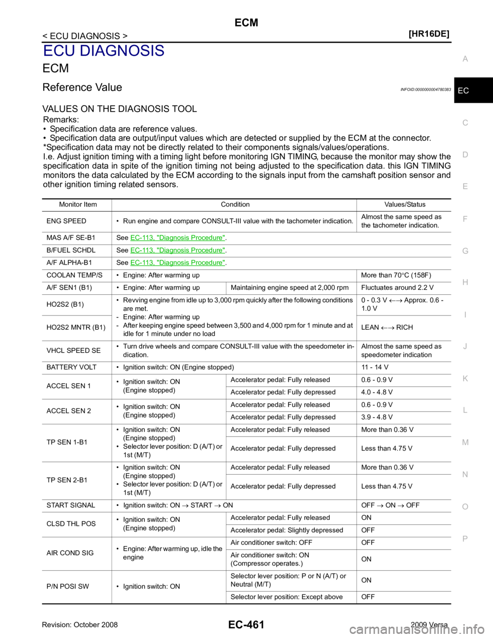
VALUES ON THE DIAGNOSIS TOOL Remarks:
• Specification data are reference values.
• Specification data are output/input values which are detected or supplied by the ECM at the connector.
*Specification data may not be directly relat ed to their components signals/values/operations.
I.e. Adjust ignition timing with a timing light before m onitoring IGN TIMING, because the monitor may show the
specification data in spite of the ignition timing not bei ng adjusted to the specification data. this IGN TIMING
monitors the data calculated by the ECM according to the signals input from the camshaft position sensor and
other ignition timing related sensors.
Monitor Item Condition Values/Status
ENG SPEED • Run engine and compare CONSULT-III value with the tachometer indication. Almost the same speed as
the tachometer indication.
MAS A/F SE-B1 See EC-113, " Diagnosis Procedure " .
B/FUEL SCHDL See EC-113, " Diagnosis Procedure " .
A/F ALPHA-B1 See EC-113, " Diagnosis Procedure " .
COOLAN TEMP/S • Engine: After warming up More than 70 °C (158F)
A/F SEN1 (B1) • Engine: After warming up Maintaining engine speed at 2,000 rpm Fluctuates around 2.2 V
HO2S2 (B1) • Revving engine from idle up to 3,000 rpm quickly after the following conditions
are met.
- Engine: After warming up
- After keeping engine speed between 3,500 and 4,000 rpm for 1 minute and at
idle for 1 minute under no load 0 - 0.3 V
←→ Approx. 0.6 -
1.0 V
HO2S2 MNTR (B1) LEAN ←→ RICH
VHCL SPEED SE • Turn drive wheels and compare CONSULT-III value with the speedometer in-
dication. Almost the same speed as
speedometer indication
BATTERY VOLT • Ignition switch: ON (Engine stopped) 11 - 14 V
ACCEL SEN 1 • Ignition switch: ON
(Engine stopped) Accelerator pedal: Fully released 0.6 - 0.9 V
Accelerator pedal: Fully depressed 4.0 - 4.8 V
ACCEL SEN 2 • Ignition switch: ON
(Engine stopped) Accelerator pedal: Fully released 0.6 - 0.9 V
Accelerator pedal: Fully depressed 3.9 - 4.8 V
TP SEN 1-B1 • Ignition switch: ON
(Engine stopped)
• Selector lever position: D (A/T) or 1st (M/T) Accelerator pedal: Fully released More than 0.36 V
Accelerator pedal: Fully depressed Less than 4.75 V
TP SEN 2-B1 • Ignition switch: ON
(Engine stopped)
• Selector lever position: D (A/T) or 1st (M/T) Accelerator pedal: Fully released More than 0.36 V
Accelerator pedal: Fully depressed Less than 4.75 V
START SIGNAL • Ignition switch: ON → START → ON OFF → ON → OFF
CLSD THL POS • Ignition switch: ON
(Engine stopped) Accelerator pedal: Fully released ON
Accelerator pedal: Slightly depressed OFF
AIR COND SIG • Engine: After warming up, idle the
engine Air conditioner switch: OFF OFF
Air conditioner switch: ON
(Compressor operates.) ON
P/N POSI SW • Ignition switch: ON Selector lever position: P or N (A/T) or
Neutral (M/T) ON
Selector lever position: Except above OFF