2009 NISSAN TIIDA Electric motor
[x] Cancel search: Electric motorPage 841 of 4331

BRC
N
O P
CONTENTS
BRAKE CONTROL SYSTEM
ABS
SERVICE INFORMATION .. ..........................
2
PRECAUTIONS .............................................. .....2
Precaution for Supplemental Restraint System
(SRS) "AIR BAG" and "SEAT BELT PRE-TEN-
SIONER" ............................................................. ......
2
Precaution for Brake System .............................. ......2
Precaution for Brake Cont rol .....................................3
Precaution for CAN System ................................ ......3
PREPARATION .............................................. .....4
Special Service Tool ........................................... ......4
Commercial Service Tool .................................... ......4
SYSTEM DESCRIPTION ................................ .....5
System Component ............................................. ......5
ABS Function ...................................................... ......5
EBD Function ...................................................... ......5
Fail-Safe Function ............................................... ......5
Hydraulic Circuit Diagram .........................................6
CAN COMMUNICATION ................................ .....7
System Description ............................................. ......7
TROUBLE DIAGNOSIS ................................. .....8
How to Perform Trouble Diagnosis for Quick and
Accurate Repair ........... .............................................
8
Component Parts and Harness Connector Loca-
tion ...................................................................... ....
11
Schematic ........................................................... ....12
Wiring Diagram - ABS - ... ........................................13 Basic Inspection ..................................................
....16
Warning Lamp and Indicator Timing .................... ....17
Control Unit Input/Output Signal Standard .......... ....17
CONSULT-III Function ( ABS) ..................................18
TROUBLE DIAGNOSIS FOR SELF-DIAG-
NOSTIC ITEMS ................................................. 24
Wheel Sensor System ......................................... ....24
ABS Control Unit Inspection ................................ ....25
Solenoid Valve System Inspection ...................... ....25
Actuator Motor, Motor Re lay, and Circuit Inspec-
tion ....................................................................... ....
26
ABS Control Unit Power and Ground Systems In-
spection ............................................................... ....
27
CAN Communication System Inspection ............. ....28
TROUBLE DIAGNOSES FOR SYMPTOMS ..... 29
ABS Works Frequently ........................................ ....29
Unexpected Pedal Action .................................... ....29
Long Stopping Distance ...................................... ....30
ABS Does Not Work ............................................ ....30
Pedal Vibration or ABS Op eration Noise .................30
WHEEL SENSORS ........................................... 32
Removal and Installation ..................................... ....32
SENSOR ROTOR .............................................. 34
Removal and Installation ..................................... ....34
ACTUATOR AND ELECTRIC UNIT (ASSEM-
BLY) .................................................................. 35
Removal and Installation ..................................... ....35
Page 843 of 4331
BRC
N
O P
Precaution for Brake Control
INFOID:0000000004307252
• During ABS operation, the brake pedal may vibrate lightly and a mechanical noise may be heard. This is normal.
• Just after starting the vehicle, the brake pedal may vibrate or motor operating noises may be heard from
engine compartment. This is normal due to the self check operation.
• Stopping distance may be longer than that of vehicles without ABS when vehicle drives on rough, gravel, or
snow-covered (fresh, deep snow) roads.
• When an error is indicated by ABS or another warning lamp, collect all necessary information from customer
(what symptoms are present under what conditions) and check for simple causes before starting diagnosis.
Besides electrical system inspection, check brake booster operation, brake fluid level, and fluid leaks.
• If incorrect tire sizes or types are installed on the vehicle or brake pads are not Genuine NISSAN parts, stop-
ping distance or steering stability may deteriorate.
• If there is a radio, antenna or related wiring near t he control module, ABS function may have a malfunction
or error.
• If aftermarket parts (car stereo, CD player, etc.) have been installed, check for incidents such as harness pinches, open circuits or improper wiring.
Precaution for CAN System INFOID:0000000004307253
• Do not apply voltage of 7.0V or higher to terminal to be measured.
• Maximum open terminal voltage of tester in use must be less than 7.0V.
• Before checking harnesses, turn ignition switch OFF and disconnect battery negative cable.
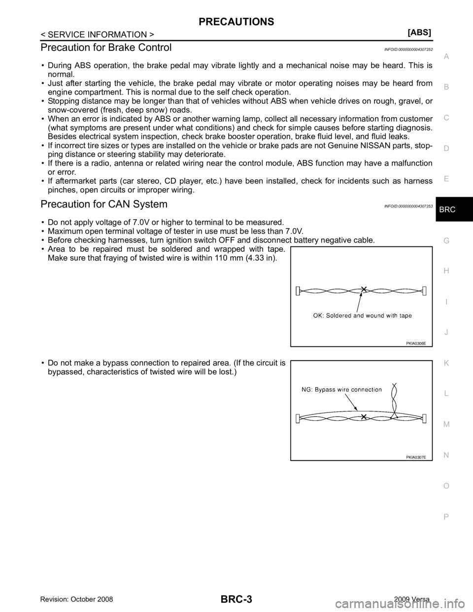
• Area to be repaired must be soldered and wrapped with tape. Make sure that fraying of twisted wire is within 110 mm (4.33 in).
• Do not make a bypass connection to repaired area. (If the circuit is bypassed, characteristics of twisted wire will be lost.)
Page 845 of 4331
BRC
N
O P
SYSTEM DESCRIPTION
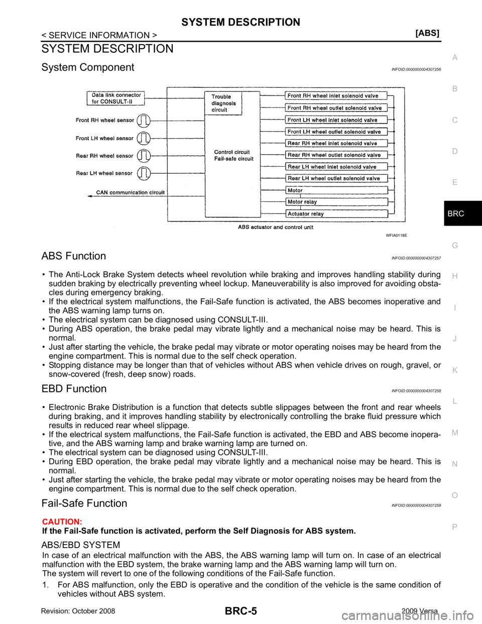
System Component INFOID:0000000004307256
ABS Function INFOID:0000000004307257
• The Anti-Lock Brake System detects wheel revolution while braking and improves handling stability during sudden braking by electrically preventing wheel lockup. Maneuverability is also improved for avoiding obsta-
cles during emergency braking.
• If the electrical system malfunctions, the Fail-Safe function is activated, the ABS becomes inoperative and
the ABS warning lamp turns on.
• The electrical system can be diagnosed using CONSULT-III.
• During ABS operation, the brake pedal may vibrate lightly and a mechanical noise may be heard. This is
normal.
• Just after starting the vehicle, the brake pedal may vibrate or motor operating noises may be heard from the
engine compartment. This is normal due to the self check operation.
• Stopping distance may be longer than that of vehicles without ABS when vehicle drives on rough, gravel, or
snow-covered (fresh, deep snow) roads.
EBD Function INFOID:0000000004307258
• Electronic Brake Distribution is a function that detec ts subtle slippages between the front and rear wheels
during braking, and it improves handling stability by elec tronically controlling the brake fluid pressure which
results in reduced rear wheel slippage.
• If the electrical system malfunctions, the Fail-Safe function is activated, the EBD and ABS become inopera-
tive, and the ABS warning lamp and brake warning lamp are turned on.
• The electrical system can be diagnosed using CONSULT-III.
• During EBD operation, the brake pedal may vibrate lightly and a mechanical noise may be heard. This is
normal.
• Just after starting the vehicle, the brake pedal may vibrate or motor operating noises may be heard from the
engine compartment. This is normal due to the self check operation.
Fail-Safe Function INFOID:0000000004307259
CAUTION:
If the Fail-Safe function is activated, perform the Self Diagnosis for ABS system.
ABS/EBD SYSTEM In case of an electrical malfunction with the ABS, the ABS warning lamp wi ll turn on. In case of an electrical
malfunction with the EBD system, the brake warni ng lamp and the ABS warning lamp will turn on.
The system will revert to one of the follo wing conditions of the Fail-Safe function.
1. For ABS malfunction, only the EBD is operative and t he condition of the vehicle is the same condition of
vehicles without ABS system.
Page 858 of 4331
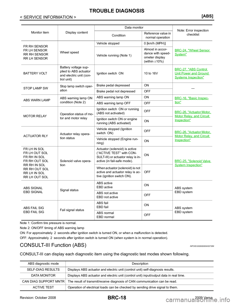
Wheel Sensor
System "
Vehicle running (Note 1)
Almost in accor-
dance with speed-
ometer display
(within ±10%)
BATTERY VOLT Battery voltage sup-
plied to ABS actuator
and electric unit (con-
trol unit) Ignition switch ON 10 to 16V
BRC-27, " ABS Control
Unit Power and Ground
Systems Inspection "
STOP LAMP SW
Stop lamp switch oper-
ation Brake pedal depressed ON
—
Brake pedal not depressed OFF
ABS WARN LAMP ABS warning lamp ON
condition (Note 2) ABS warning lamp ON ON
BRC-16, " Basic Inspec-
tion "
ABS warning lamp OFF OFF
MOTOR RELAY Operation status of mo-
tor and motor relay Ignition switch ON or running
(ABS not activated) OFF
BRC-26, " Actuator Motor,
Motor Relay, and Circuit
Inspection "Ignition switch ON or engine
running (ABS activated) ON
ACTUATOR RLY Actuator relay opera-
tion status Vehicle stopped (Ignition
switch ON) OFF
BRC-26, " Actuator Motor,
Motor Relay, and Circuit
Inspection "Vehicle stopped (Engine run-
ning) ON
FR LH IN SOL
FR LH OUT SOL
FR RH IN SOL
FR RH OUT SOL
RR RH IN SOL
RR RH OUT SOL
RR LH IN SOL
RR LH OUT SOL Solenoid valve opera-
tion Actuator (solenoid) is active
(“ACTIVE TEST” with CON-
SULT-III) or actuator relay is in-
active (in fail-safe mode). ON
BRC-25, " Solenoid Valve
System Inspection "
When actuator (solenoid) is not
active and actuator relay is ac-
tive (ignition switch ON). OFF
ABS SIGNAL
EBD SIGNAL Signal statusABS active
EBD active ON
ABS system
EBD system
ABS not active
EBD not active OFF
ABS FAIL SIG
EBD FAIL SIG Fail signal statusABS fail
EBD fail ON
ABS system
EBD system
ABS normal
EBD normal OFFABS diagnostic mo
de Description
SELF-DIAG RESULTS Displays ABS actuator and electric unit (control unit) self-diagnosis results.
DATA MONITOR Displays ABS actuator and electric unit (control unit) input/output data in real time.
CAN DIAG SUPPORT MNTR The result of transmit/receive diagnosis of CAN communication can be read. ACTIVE TEST Operation of electrical loads can be checked by sending drive signal to them.
Page 860 of 4331
![NISSAN TIIDA 2009 Service Repair Manual Wheel Sensor
System " (Note 1)
RR LH SENSOR-1
[C1102] Circuit of rear LH wheel sensor is open.
FR RH SENSOR-1
[C1103] Circuit of front RH wheel sensor is open.
FR LH SENSOR-1
[C1104] Circuit of fron NISSAN TIIDA 2009 Service Repair Manual Wheel Sensor
System " (Note 1)
RR LH SENSOR-1
[C1102] Circuit of rear LH wheel sensor is open.
FR RH SENSOR-1
[C1103] Circuit of front RH wheel sensor is open.
FR LH SENSOR-1
[C1104] Circuit of fron](/manual-img/5/57398/w960_57398-859.png)
Wheel Sensor
System " (Note 1)
RR LH SENSOR-1
[C1102] Circuit of rear LH wheel sensor is open.
FR RH SENSOR-1
[C1103] Circuit of front RH wheel sensor is open.
FR LH SENSOR-1
[C1104] Circuit of front LH wheel sensor is open.
RR RH SENSOR-2
[C1105] When the circuit in the rear RH wheel sensor is short-circuited or
when the sensor power voltage is outside the standard. When the
distance between the wheel sensor and sensor rotor is too large
and the sensor pulse cannot be recognized by the control unit.
RR LH SENSOR-2
[C1106] When the circuit in the rear LH wheel sensor is short-circuited or
when the sensor power voltage is outside the standard. When the
distance between the wheel sensor and sensor rotor is too large
and the sensor pulse cannot be recognized by the control unit.
FR RH SENSOR-2
[C1107] When the circuit in the front RH wheel sensor is short-circuited or
when the sensor power voltage is outside the standard. When the
distance between the wheel sensor and sensor rotor is too large
and the sensor pulse cannot be recognized by the control unit.
FR LH SENSOR-2
[C1108] When the circuit in the front LH wheel sensor is short-circuited or
when the sensor power voltage is outside the standard. When the
distance between the wheel sensor and sensor rotor is too large
and the sensor pulse cannot be recognized by the control unit.
ABS SENSOR
[ABNORMAL SIGNAL]
[C1115] Wheel sensor input is abnormal.
BATTERY VOLTAGE
[ABNORMAL]
[C1109] ABS actuator and electric unit (control unit) power voltage is too
low. BRC-27, " ABS Control
Unit Power and Ground
Systems Inspection "
CONTROLLER FAILURE
[C1110] Internal malfunction of ABS actuator
and electric unit (control unit)BRC-25, " ABS Control
Unit Inspection "
PUMP MOTOR
[C1111] During actuator motor operation with ON, when actuator motor
turns OFF or when control line for actuator motor relay is open. BRC-26, " Actuator Mo-
tor, Motor Relay, and Cir-
cuit Inspection "During actuator motor operation with OFF, when actuator motor
turns ON or when control line for relay is shorted to ground.
FR LH IN ABS SOL
[C1120] Circuit of front LH IN ABS solenoid
is open or shorted, or control
line is open or shorted to power supply or ground.
BRC-25, " Solenoid Valve
System Inspection "FR LH OUT ABS SOL
[C1121] Circuit of front LH OUT ABS solenoid is open or shorted, or control
line is open or shorted to power supply or ground.
FR RH IN ABS SOL
[C1122] Circuit of front RH IN ABS solenoid is open or shorted, or control
line is open or shorted to power supply or ground.
FR RH OUT ABS SOL
[C1123] Circuit of front RH OUT ABS solenoid is open or shorted, or con-
trol line is open or shorted to power supply or ground.
RR LH IN ABS SOL
[C1124] Circuit of rear LH IN ABS solenoid
is open or shorted, or control
line is open or shorted to power supply or ground.
RR LH OUT ABS SOL
[C1125] Circuit of rear LH OUT ABS solenoid
is open or shorted, or control
line is open or shorted to power supply or ground.
RR RH IN ABS SOL
[C1126] Circuit of rear RH IN ABS solenoid
is open or shorted, or control
line is open or shorted to power supply or ground.
RR RH OUT ABS SOL
[C1127] Circuit of rear RH OUT ABS solenoid is open or shorted, or control
line is open or shorted to power supply or ground.
Page 861 of 4331
BRC
N
O P
Note 1: If wheel sens
or 2 for each wheel is indicated, check ABS actuator and electric unit (control unit) power supply voltage in addition
to wheel sensor circuit check.
Note 2: If multiple malfunctions are detected including CAN communication line [U1000], perform diagnosis for CAN communication line
first.
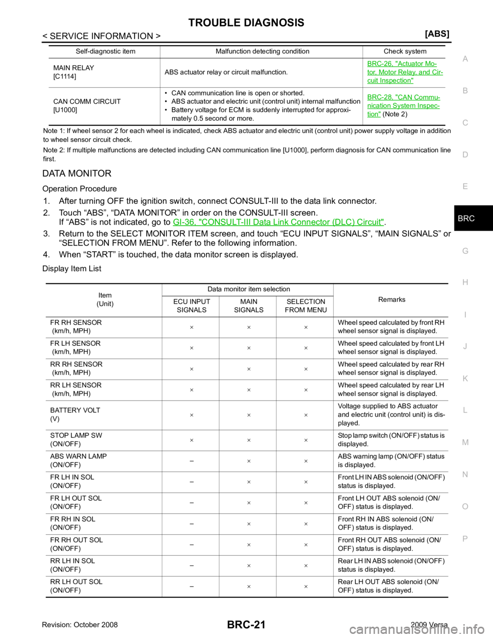
DATA MONITOR
Operation Procedure 1. After turning OFF the ignition switch, c onnect CONSULT-III to the data link connector.
2. Touch “ABS”, “DATA MONITOR” in order on the CONSULT-III screen. If “ABS” is not indicated, go to GI-36, " CONSULT-III Data Link Connector (DLC) Circuit " .
3. Return to the SELECT MONITOR ITEM screen, and touch “ECU INPUT SIGNALS”, “MAIN SIGNALS” or
“SELECTION FROM MENU”. Refer to the following information.
4. When “START” is touched, the data monitor screen is displayed.
Display Item List MAIN RELAY
[C1114] ABS actuator relay or circuit malfunction. BRC-26, " Actuator Mo-
tor, Motor Relay, and Cir-
cuit Inspection "
CAN COMM CIRCUIT
[U1000] • CAN communication line is open or shorted.
• ABS actuator and electric unit (control unit) internal malfunction
• Battery voltage for ECM is suddenly interrupted for approxi-
mately 0.5 second or more. BRC-28, " CAN Commu-
nication System Inspec-
tion " (Note 2)
Self-diagnostic item Malfunction detecting condition Check system Item
(Unit) Data monitor item selection
Remarks
ECU INPUT
SIGNALS MAIN
SIGNALS SELECTION
FROM MENU
FR RH SENSOR
(km/h, MPH) × × × Wheel speed calculated by front RH
wheel sensor signal is displayed.
FR LH SENSOR
(km/h, MPH) × × ×
Wheel speed calculated by front LH
wheel sensor signal is displayed.
RR RH SENSOR
(km/h, MPH) × × × Wheel speed calculated by rear RH
wheel sensor signal is displayed.
RR LH SENSOR
(km/h, MPH) × × × Wheel speed calculated by rear LH
wheel sensor signal is displayed.
BATTERY VOLT
(V) × × × Voltage supplied to ABS actuator
and electric unit (control unit) is dis-
played.
STOP LAMP SW
(ON/OFF) × × × Stop lamp switch (ON/OFF) status is
displayed.
ABS WARN LAMP
(ON/OFF) –
× × ABS warning lamp (ON/OFF) status
is displayed.
FR LH IN SOL
(ON/OFF) –
× × Front LH IN ABS solenoid (ON/OFF)
status is displayed.
FR LH OUT SOL
(ON/OFF) –
× × Front LH OUT ABS solenoid (ON/
OFF) status is displayed.
FR RH IN SOL
(ON/OFF) –
× × Front RH IN ABS solenoid (ON/
OFF) status is displayed.
FR RH OUT SOL
(ON/OFF) –
× × Front RH OUT ABS solenoid (ON/
OFF) status is displayed.
RR LH IN SOL
(ON/OFF) –
× × Rear LH IN ABS solenoid (ON/OFF)
status is displayed.
RR LH OUT SOL
(ON/OFF) –
× × Rear LH OUT ABS solenoid (ON/
OFF) status is displayed.
Page 866 of 4331
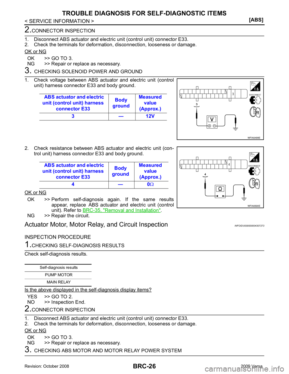
OK >> GO TO 3.
NG >> Repair or replace as necessary. OK >> Perform self-diagnosis again. If the same results
appear, replace ABS actuator and electric unit (control
unit). Refer to BRC-35, " Removal and Installation " .
NG >> Repair the circuit.
Actuator Motor, Motor Rela y, and Circuit Inspection INFOID:0000000004307273
INSPECTION PROCEDURE YES >> GO TO 2.
NO >> Inspection End. OK >> GO TO 3.
NG >> Repair or replace as necessary.
Page 951 of 4331

CVT
N
O
P
N
Description ..........................................................
..
293
CONSULT-III Refe rence Value in Data Monitor
Mode ................................................................... ..
293
On Board Diagnosis Logic .................................. ..293
Possible Cause ................................................... ..293
DTC Confirmation Procedure .............................. ..293
Diagnosis Procedure ........................................... ..293
DTC P1701 TRANSMISSION CONTROL
MODULE (POWER SUPPLY) ........................ ..295
Description .......................................................... ..295
On Board Diagnosis Logic .................................. ..295
Possible Cause ................................................... ..295
DTC Confirmation Procedure .............................. ..295
Wiring Diagram - CVT - POWER ........................ ..296
Diagnosis Procedure ........................................... ..297
DTC P1705 THROTTLE POSITION SENSOR ..299
Description .......................................................... ..299
CONSULT-III Refe rence Value in Data Monitor
Mode ................................................................... ..
299
On Board Diagnosis Logic .................................. ..299
Possible Cause ................................................... ..299
DTC Confirmation Procedure .............................. ..299
Diagnosis Procedure ........................................... ..299
DTC P1722 ESTM VEHICLE SPEED SIGNAL ..301
Description .......................................................... ..301
CONSULT-III Refe rence Value in Data Monitor
Mode ................................................................... ..
301
On Board Diagnosis Logic .................................. ..301
Possible Cause ................................................... ..301
DTC Confirmation Procedure .............................. ..301
Diagnosis Procedure ........................................... ..301
DTC P1723 CVT SPEED SENSOR FUNC-
TION ............................................................... ..303
Description .......................................................... ..303
On Board Diagnosis Logic .................................. ..303
Possible Cause ................................................... ..303
DTC Confirmation Procedure .............................. ..303
Diagnosis Procedure ........................................... ..303
DTC P1726 ELECTRIC THROTTLE CON-
TROL SYSTEM .............................................. ..
305
Description .......................................................... ..305
On Board Diagnosis Logic .................................. ..305
Possible Cause ................................................... ..305
DTC Confirmation Procedure .............................. ..305
Diagnosis Procedure ........................................... ..305
DTC P1740 LOCK-UP SELECT SOLENOID
VALVE CIRCUIT ............................................ ..
306
Description .......................................................... ..306
CONSULT-III Refe rence Value in Data Monitor
Mode ................................................................... ..
306
On Board Diagnosis Logic .................................. ..306
Possible Cause ................................................... ..306
DTC Confirmation Procedure .............................. ..306
Wiring Diagram - CVT - L/USSV ......................... ..307 Diagnosis Procedure ...........................................
..308
Component Inspection ......................................... ..309
DTC P1745 LINE PRESSURE CONTROL ..... 310
Description ........................................................... ..310
On Board Diagnosis Logic ................................... ..310
Possible Cause .................................................... ..310
DTC Confirmation Procedure .............................. ..310
Diagnosis Procedure ........................................... ..310
DTC P1777 STEP MOTOR - CIRCUIT ........... 311
Description ........................................................... ..311
CONSULT-III Reference Va lue in Data Monitor
Mode .................................................................... ..
311
On Board Diagnosis Logic ................................... ..311
Possible Cause .................................................... ..311
DTC Confirmation Procedure .............................. ..311
Wiring Diagram - CVT - STM ............................... ..312
Diagnosis Procedure ........................................... ..313
Component Inspection ......................................... ..314
DTC P1778 STEP MOTOR - FUNCTION ....... 315
Description ........................................................... ..315
CONSULT-III Reference Va lue in Data Monitor
Mode .................................................................... ..
315
On Board Diagnosis Logic ................................... ..315
Possible Cause .................................................... ..315
DTC Confirmation Procedure .............................. ..315
Diagnosis Procedure ........................................... ..316
OVERDRIVE CONTROL SWITCH .................. 317
Description ........................................................... ..317
CONSULT-III Reference Va lue in Data Monitor
Mode .................................................................... ..
317
Wiring Diagram - CVT - ODSW ........................... ..318
Diagnosis Procedure ........................................... ..318
Component Inspection ......................................... ..320
SHIFT POSITION INDICATOR CIRCUIT ........ 322
Description ........................................................... ..322
CONSULT-III Reference Va lue in Data Monitor
Mode .................................................................... ..
322
Diagnosis Procedure ........................................... ..322
TROUBLE DIAGNOSIS FOR SYMPTOMS .... 323
Wiring Diagram - CVT - NONDTC ....................... ..323
O/D OFF Indicator Lamp Does Not Come On ..... ..325
Engine Cannot Be Started in "P" and "N" Position ..327
In "P" Position, Vehicle Moves Forward or Back-
ward When Pushed ............................................. ..
327
In "N" Position, Vehicle Moves ............................ ..328
Large Shock "N" → "R" Position .......................... ..328
Vehicle Does Not Creep Backward in "R" Position ..329
Vehicle Does Not Creep Forward in "D" or "L" Po-
sition .................................................................... ..
330
Vehicle Speed Does Not Change in "L" Position . ..331
Vehicle Speed Does Not Change in overdrive-off
mode .................................................................... ..
332
Vehicle Speed Does Not Change in "D" Position .. 333
Vehicle Does Not Decelerate by Engine Brake ... ..333