2009 NISSAN TIIDA wheel
[x] Cancel search: wheelPage 3242 of 4331
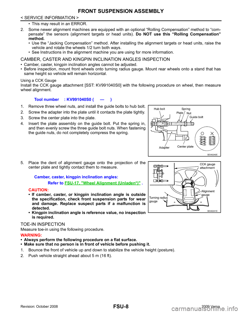
Wheel Alignment (Unladen*) " .
Page 3243 of 4331
FSU
N
O P
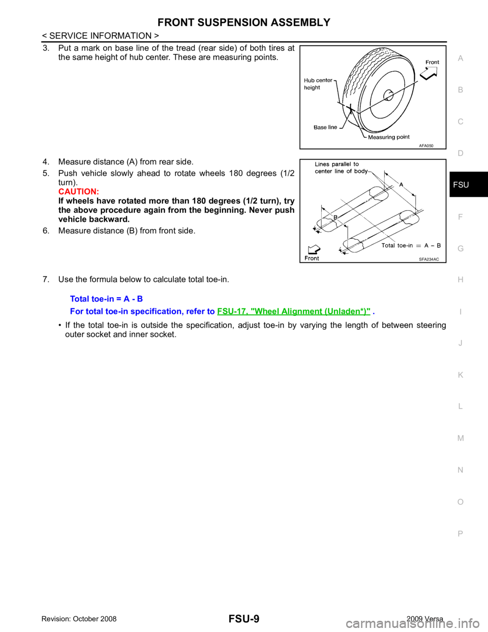
3. Put a mark on base line of the tread (rear side) of both tires at
the same height of hub center. These are measuring points.
4. Measure distance (A) from rear side.
5. Push vehicle slowly ahead to rotate wheels 180 degrees (1/2 turn).
CAUTION:
If wheels have rotated more than 180 degrees (1/2 turn), try
the above procedure again from the beginning. Never push
vehicle backward.
6. Measure distance (B) from front side.
7. Use the formula below to calculate total toe-in. • If the total toe-in is outside the specification, adj ust toe-in by varying the length of between steering
outer socket and inner socket. SFA234AC
Wheel Alignment (Unladen*) " .
Page 3245 of 4331
FRONT SUSPENSION ASSEMBLY
FSU-11
< SERVICE INFORMATION >
C
D
F
G H
I
J
K L
M A
B FSU
N
O P
Removal and Installation
INFOID:0000000004305866
REMOVAL 1. Separate intermediate shaft from steering gear pinion shaft. Refer to PS-9, " Removal and Installation " .
2. Remove front tires from vehicle using a power tool.
3. Remove wheel sensor from steering knuckle. Refer to BRC-32 .
CAUTION:
Do not pull on wheel sensor harness.
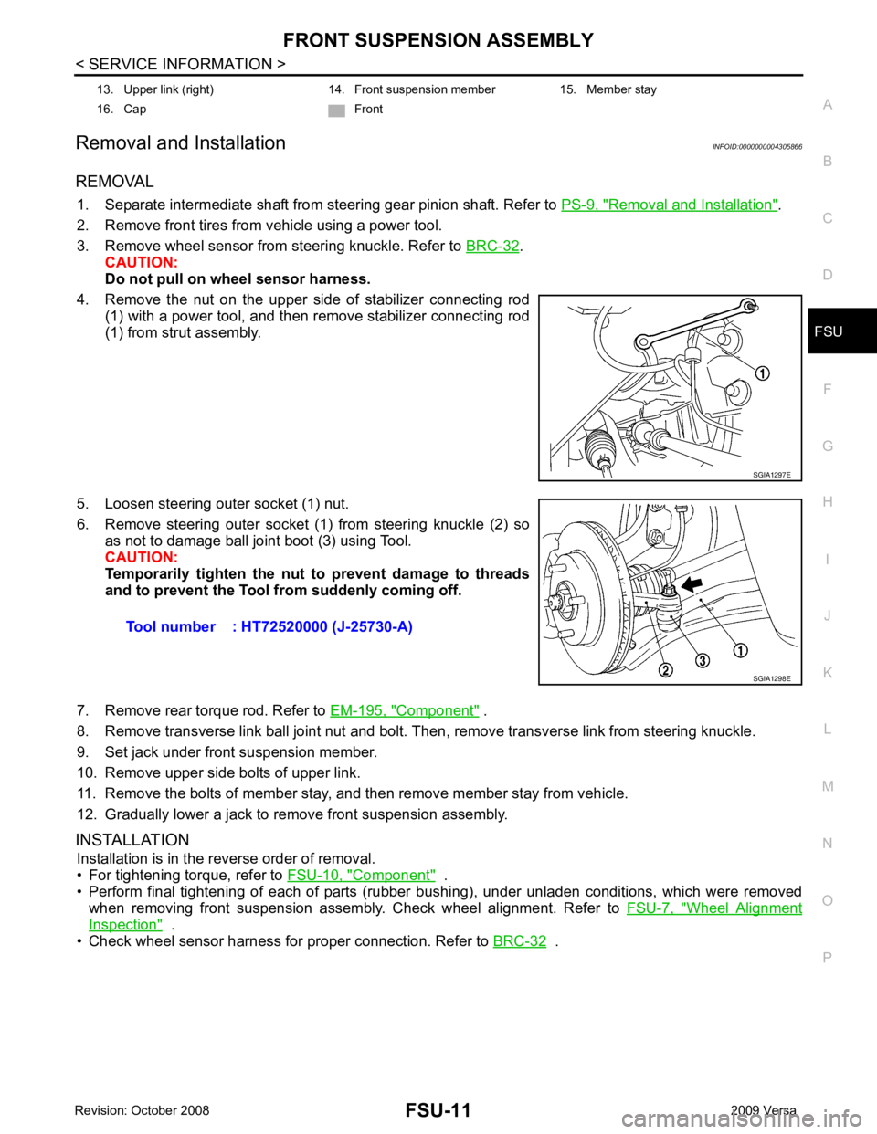
4. Remove the nut on the upper side of stabilizer connecting rod (1) with a power tool, and then remove stabilizer connecting rod
(1) from strut assembly.
5. Loosen steering outer socket (1) nut.
6. Remove steering outer socket (1) from steering knuckle (2) so as not to damage ball joint boot (3) using Tool.
CAUTION:
Temporarily tighten the nut to prevent damage to threads
and to prevent the Tool fr om suddenly coming off.
7. Remove rear torque rod. Refer to EM-195, " Component " .
8. Remove transverse link ball joint nut and bolt. Then, remove transverse link from steering knuckle.
9. Set jack under front suspension member.
10. Remove upper side bolts of upper link.
11. Remove the bolts of member stay, and then remove member stay from vehicle.
12. Gradually lower a jack to remove front suspension assembly.
INSTALLATION Installation is in the reverse order of removal.
• For tightening torque, refer to FSU-10, " Component " .
• Perform final tightening of each of parts (rubber bushing), under unladen conditions, which were removed when removing front suspension assembly. Check wheel alignment. Refer to FSU-7, " Wheel Alignment
Inspection " .
• Check wheel sensor harness for proper connection. Refer to BRC-32 .
13. Upper link (right) 14. Front suspension member 15. Member stay
16. Cap Front SGIA1297E
Tool number : HT72520000 (J-25730-A)
SGIA1298E
Page 3246 of 4331
FSU-12< SERVICE INFORMATION >
COIL SPRING AND STRUT
COIL SPRING AND STRUT
Removal and Installation INFOID:0000000004305867
REMOVAL
1. Remove cowl top panel. Refer to EI-22, " Removal and Installation " .
2. Remove front tires using power tool.
3. Remove harness of wheel sensor from strut assembly. Refer to BRC-32, " Removal and Installation " .
CAUTION:
Do not pull on wheel sensor harness.
4. Remove brake hose lock plate. Refer to BR-12, " Rear Brake Tube and Hose " .
5. Remove the nut on the upper side of stabilizer c onnecting rod using power tool, and then remove stabi-
lizer connecting rod from strut assembly.
6. Remove nuts and bolts, and then remove steering knuckle from strut assembly. Refer to FSU-10, " Component " .
7. Remove the strut mounting insulator bolts, then remove strut assembly.
INSTALLATION
Installation is in the reverse order of removal.
• For tightening torque, refer to FSU-10, " Component " .
• Perform final tightening of bolts and nuts at the strut assembly lower side (rubber bushing) under unladen
conditions with tires on level ground. Check wheel alignment. Refer to FSU-7, " Wheel Alignment Inspection "
.
• Check wheel sensor harness for proper connection. Refer to BRC-32 .
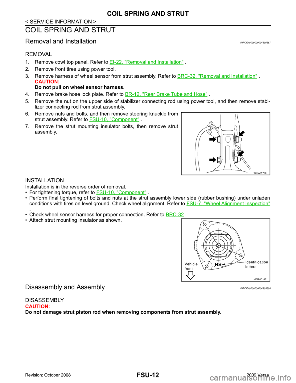
• Attach strut mounting insulator as shown.
Disassembly and Assembly INFOID:0000000004305868
DISASSEMBLY
CAUTION:
Do not damage strut piston rod when removing components from strut assembly. WEIA0179E
MEIA0014E
Page 3249 of 4331
FSU
N
O P
TRANSVERSE LINK
Removal and Installation INFOID:0000000004305869
REMOVAL 1. Remove front tires using power tool.
2. Remove transverse link ball joint nut and bolt. Then, remove transverse link from steering knuckle.
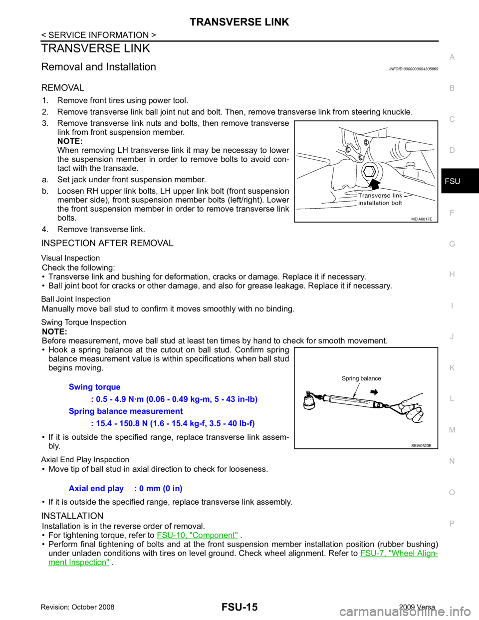
3. Remove transverse link nuts and bolts, then remove transverse link from front suspension member.
NOTE:
When removing LH transverse link it may be necessay to lower
the suspension member in order to remove bolts to avoid con-
tact with the transaxle.
a. Set jack under front suspension member.
b. Loosen RH upper link bolts, LH upper link bolt (front suspension member side), front suspension member bolts (left/right). Lower
the front suspension member in order to remove transverse link
bolts.
4. Remove transverse link.
INSPECTION AFTER REMOVAL
Visual Inspection Check the following:
• Transverse link and bushing for deformation, cracks or damage. Replace it if necessary.
• Ball joint boot for cracks or other damage, and also for grease leakage. Replace it if necessary.
Ball Joint Inspection Manually move ball stud to confirm it moves smoothly with no binding.
Swing Torque Inspection NOTE:
Before measurement, move ball stud at least t en times by hand to check for smooth movement.
• Hook a spring balance at the cutout on ball stud. Confirm spring balance measurement value is within specifications when ball stud
begins moving.
• If it is outside the specified range, replace transverse link assem- bly.
Axial End Play Inspection • Move tip of ball stud in axial direction to check for looseness.
• If it is outside the specified range, replace transverse link assembly.
INSTALLATION Installation is in the reverse order of removal.
• For tightening torque, refer to FSU-10, " Component " .
• Perform final tightening of bolts and at the front suspension member installation position (rubber bushing)
under unladen conditions with tires on level ground. Check wheel alignment. Refer to FSU-7, " Wheel Align-
ment Inspection " .
Page 3251 of 4331
SERVICE DATA AND SPECIFICATIONS (SDS)
FSU-17
< SERVICE INFORMATION >
C
D
F
G H
I
J
K L
M A
B FSU
N
O P
SERVICE DATA AND SPECIFICATIONS (SDS)
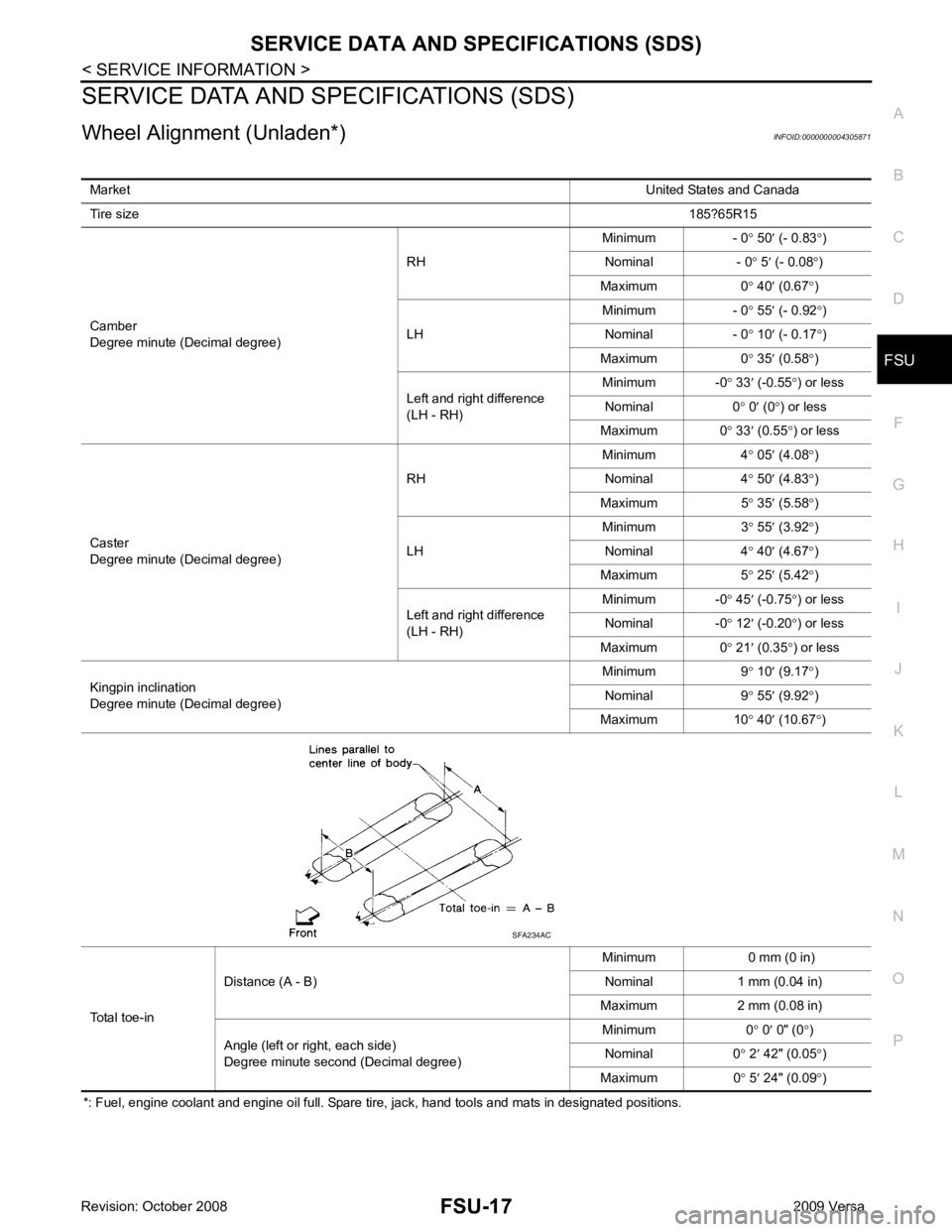
Wheel Alignment (Unladen*) INFOID:0000000004305871
*: Fuel, engine coolant and engine oil full. Spare tire, jack, hand tools and mats in designated positions. Market
United States and Canada
Tire size 185?65R15
Camber
Degree minute (Decimal degree) RH
Minimum - 0
° 50 ′ (- 0.83 °)
Nominal - 0 ° 5 ′ (- 0.08 °)
Maximum 0 ° 40 ′ (0.67 °)
LH Minimum - 0
° 55 ′ (- 0.92 °)
Nominal - 0 ° 10 ′ (- 0.17 °)
Maximum 0 ° 35 ′ (0.58 °)
Left and right difference
(LH - RH) Minimum -0
° 33 ′ (-0.55 °) or less
Nominal 0 ° 0 ′ (0 °) or less
Maximum 0 ° 33 ′ (0.55 °) or less
Caster
Degree minute (Decimal degree) RH
Minimum 4
° 05 ′ (4.08 °)
Nominal 4 ° 50 ′ (4.83 °)
Maximum 5 ° 35 ′ (5.58 °)
LH Minimum 3
°
55 ′ (3.92 °)
Nominal 4 ° 40 ′ (4.67 °)
Maximum 5 ° 25 ′ (5.42 °)
Left and right difference
(LH - RH) Minimum -0
° 45 ′ (-0.75 °) or less
Nominal -0 ° 12 ′ (-0.20 °) or less
Maximum 0 ° 21 ′ (0.35 °) or less
Kingpin inclination
Degree minute (Decimal degree) Minimum 9
° 10 ′ (9.17 °)
Nominal 9 ° 55 ′ (9.92 °)
Maximum 10 ° 40 ′ (10.67 °)
Total toe-in Distance (A - B)
Minimum 0 mm (0 in)
Nominal 1 mm (0.04 in)
Maximum 2 mm (0.08 in)
Angle (left or right, each side)
Degree minute second (Decimal degree) Minimum 0
° 0 ′ 0" (0 °)
Nominal 0 ° 2 ′ 42" (0.05 °)
Maximum 0 ° 5 ′ 24" (0.09 °) SFA234AC
Page 3253 of 4331
FSU
N
O P
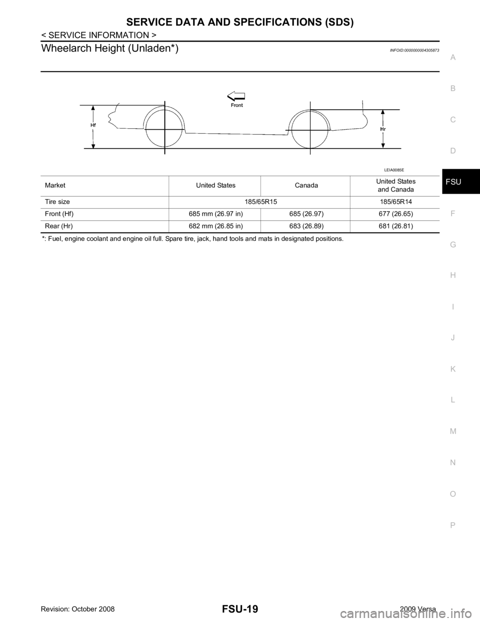
Wheelarch Height (Unladen*)
INFOID:0000000004305873
*: Fuel, engine coolant and engine oil full. Spare tire, jack, hand tools and mats in designated positions. Market United States Canada
United States
and Canada
Tire size 185/65R15 185/65R14
Front (Hf) 685 mm (26.97 in) 685 (26.97) 677 (26.65)
Rear (Hr) 682 mm (26.85 in) 683 (26.89) 681 (26.81)
Page 3254 of 4331

GI
SECTION GI
N
O P
CONTENTS
GENERAL INFORMATION
SERVICE INFORMATION .. ..........................2
PRECAUTIONS .............................................. .....2
Description .......................................................... ......2
Precaution for Supplemental Restraint System
(SRS) "AIR BAG" and "SEAT BELT PRE-TEN-
SIONER" ............................................................. ......
2
Precaution Necessary fo r Steering Wheel Rota-
tion After Battery Disconnect ............................... ......
2
General Precaution ............................................. ......3
Precaution for Three Way Catalyst ..................... ......4
Precaution for Fuel (Unleaded Regular Gasoline
Recommended) ................................................... ......
4
Precaution for Multiport Fuel Injection System or
Engine Control System ....................................... ......
5
Precaution for Hoses ........................................... ......5
Precaution for Engine Oils .................................. ......6
Precaution for Air Conditioning ........................... ......6
HOW TO USE THIS MANUAL ....................... .....7
Description .......................................................... ......7
Terms .................................................................. ......7
Units .................................................................... ......7
Contents .............................................................. ......7
Relation between Illustrations and Descriptions . ......8
Component .......................................................... ......8
How to Follow Trouble Diagnosis ........................ ......9
How to Read Wiring Diagr am ..................................13
Abbreviations ...................................................... ....20
SERVICE INFORMATION FOR ELECTRICAL
INCIDENT ....................................................... ....
22
How to Check Terminal ...........................................22 How to Perform Efficient Diagnosis for an Electri-
cal Incident .......................................................... ....
25
Control Units and Electrical Parts ........................ ....32
CONSULT-III CHECKING SYSTEM ................. 35
Description ........................................................... ....35
Function and System Application ........................ ....35
CONSULT-III Data Link Connector (DLC) Circuit ....36
LIFTING POINT ................................................. 38
Special Service Tool ............................................ ....38
Garage Jack and Safety Stand and 2-Pole Lift ... ....38
Board-On Lift ....................................................... ....39
TOW TRUCK TOWING ..................................... 40
Tow Truck Towing ............................................... ....40
Vehicle Recovery (Freeing a Stuck Vehicle) ....... ....40
TIGHTENING TORQUE OF STANDARD
BOLTS ............................................................... 41
Tightening Torque Table ..................................... ....41
RECOMMENDED CHEMICAL PRODUCTS
AND SEALANTS ............................................... 42
Recommended Chemical Product and Sealant ... ....42
IDENTIFICATION INFORMATION .................... 43
Model Variation .................................................... ....43
Dimensions .......................................................... ....46
Wheels & Tires .................................................... ....46
TERMINOLOGY ................................................ 47
SAE J1930 Terminology List ............................... ....47