Page 4062 of 4331
Removal and Instal-
lation " .
CHECKING STEERING WHEEL PLAY
• Turn steering wheel so that front wheels come to the straight-ahead position. Start engine and lightly turn
steering wheel to the left and right until front wheels start to move. Measure steering wheel movement on the
outer circumference.
• When the measurement value is outside the standard val ue, check backlash for each joint of steering col-
umn assembly and installation condition of steering gear assembly.
CHECKING NEUTRAL POSITION STEERING WHEEL
• Make sure that steering gear assembly, steering colu mn assembly and steering wheel are installed in the
correct position.
• Perform neutral position inspection after wheel alignment. Refer to PS-2, " Precaution for Supplemental
Restraint System (SRS) "AIR BA
G" and "SEAT BELT PRE-TENSIONER" " .
• Set vehicle to the straight-ahead position and c onfirm steering wheel is in the neutral position.
• Loosen outer socket lock nut and turn inner socket to left and right equally to make fine adjustments if steer-
ing wheel is not in the neutral position.
CHECKING STEERING WHEEL TURNING FORCE
1. Park vehicle on a level and dry surface, set parking brake.
2. Start engine.
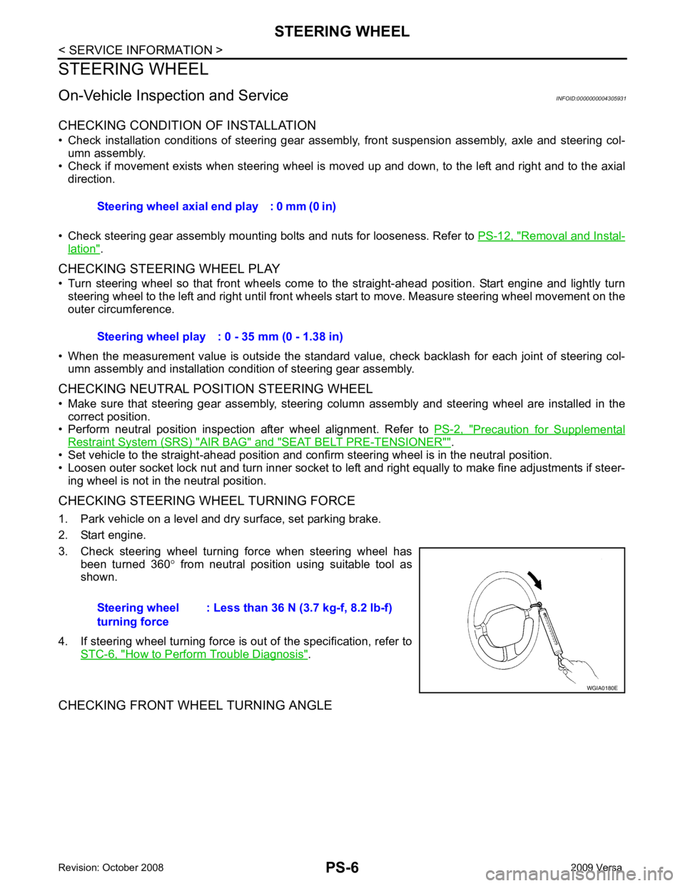
3. Check steering wheel turning force when steering wheel has been turned 360 ° from neutral position using suitable tool as
shown.
4. If steering wheel turning force is out of the specification, refer to STC-6, " How to Perform Trouble Diagnosis " .
CHECKING FRONT WHEEL TURNING ANGLE Steering wheel axial end play : 0 mm (0 in)
Steering wheel play : 0 - 35 mm (0 - 1.38 in)
Steering wheel
turning force : Less than 36 N (3.7 kg-f, 8.2 lb-f)
Page 4063 of 4331
PS
N
O P
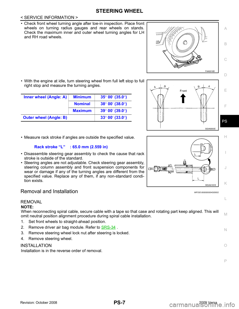
• Check front wheel turning angle after toe-in inspection. Place front
wheels on turning radius gauges and rear wheels on stands.
Check the maximum inner and outer wheel turning angles for LH
and RH road wheels.
• With the engine at idle, turn steering wheel from full left stop to full right stop and measure the turning angles.
• Measure rack stroke if angles are outside the specified value.
• Disassemble steering gear assembly to check the cause that rack stroke is outside of the standard.
• Steering angles are not adjustabl e. Check steering gear assembly,
steering column assembly and front suspension components for
wear or damage if any of the turning angles are different from the
specified value. Replace any of them, if any non-standard condi-
tion exists.
Removal and Installation INFOID:0000000004305932
REMOVAL NOTE:
When reconnecting spiral cable, secure cable with a tape so that case and rotating part keep aligned. This will
omit neutral position alignment procedure during spiral cable installation.
1. Set front wheels to straight-ahead position.
2. Remove driver air bag module. Refer to SRS-34 .
3. Remove steering wheel lock nut after steering is locked.
4. Remove steering wheel.
INSTALLATION Installation is in the reverse order of removal.
Page 4065 of 4331
PS
N
O P
STEERING COLUMN
Removal and Installation INFOID:0000000004305933
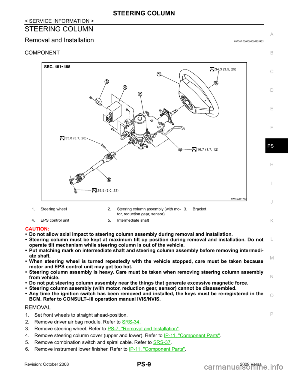
COMPONENT
CAUTION:
• Do not allow axial impact to steering colu mn assembly during removal and installation.
• Steering column must be kept at maximum tilt up position during removal and installation. Do not
operate tilt mechanism while steeri ng column is out of the vehicle.
• Put matching mark on intermediate shaft and st eering column assembly before removing intermedi-
ate shaft.
• When steering wheel is turned re peatedly with the vehicle stopped, care must be taken because
motor and EPS control unit may get too hot.
• Steering column assembly is heavy . Care must be taken when removing steering column assembly
from vehicle.
• Do not put steering column assem bly near the things that generate excessive magnetic force.
• Steering column assembly (with motor, reduc tion gear, sensor) cannot be disassembled.
• Any time the ignition switch h as been removed and installed, the keys must be re-registered in the
BCM. Refer to CONSULT–III ope ration manual IVIS/NVIS.
REMOVAL 1. Set front wheels to straight ahead-position.
2. Remove driver air bag module. Refer to SRS-34 .
3. Remove steering wheel. Refer to PS-7, " Removal and Installation " .
4. Remove steering column cover (upper and lower). Refer to IP-11, " Component Parts " .
5. Remove combination switch and spiral cable. Refer to SRS-37 .
6. Remove instrument lower finisher. Refer to IP-11, " Component Parts " .
1. Steering wheel 2. Steering column assembly (with mo-
tor, reduction gear, sensor)3. Bracket
4. EPS control unit 5. Intermediate shaft B
Page 4068 of 4331
Rotation " .
5. Loosen steering outer socket (1) mounting nut.
6. Remove steering outer socket (1) from steering knuckle (2) so as not to damage ball joint boot (3) using the ball joint remover
(suitable tool).
CAUTION:
Temporarily tighten the nut to prevent damage to threads
and to prevent the ball joint remover (suitable tool) from
suddenly coming off.
7. Remove front suspension member. Refer to FSU-11, " Removal and Installation " .
8. Remove mounting bolts and nuts of steering gear assembly.
INSTALLATION
Installation is in the reverse order of removal.
• Clean mounting surface on the body side of lower dash seal when installing steering gear assembly.
• Check wheel alignment under unladen conditions with tires on level ground. Refer to FSU-7, " Wheel Align-
ment Inspection " .
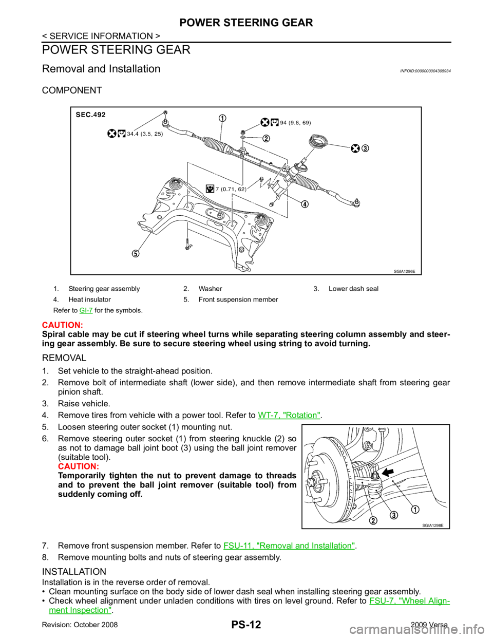
1. Steering gear assembly 2. Washer 3. Lower dash seal
4. Heat insulator 5. Front suspension member
Refer to GI-7 for the symbols.
SGIA1298E
Page 4069 of 4331
PS
N
O P
INSPECTION AFTER INSTALLATION
Rotate steering wheel to check for decentered conditi on, binding, noise or excessive steering effort.
Disassembly and Assembly INFOID:0000000004305935
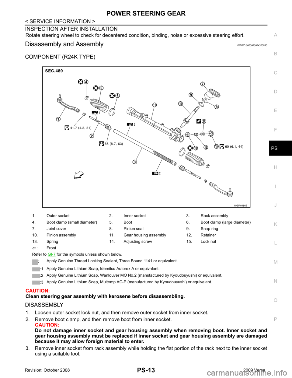
COMPONENT (R24K TYPE)
CAUTION:
Clean steering gear assembly with kerosene before disassembling.
DISASSEMBLY 1. Loosen outer socket lock nut, and then re move outer socket from inner socket.
2. Remove boot clamp, and then re move boot from inner socket.
CAUTION:
Do not damage inner socket an d gear housing assembly when re moving boot. Inner socket and
gear housing assembly must be replaced if inne r socket and gear housing assembly are damaged
because it may allow fore ign material to enter.
3. Remove inner socket from rack assembly while holdi ng the flat portion of the rack next to the inner socket
using a suitable tool.
1. Outer socket 2. Inner socket 3. Rack assembly
4. Boot clamp (small diameter) 5. Boot 6. Boot clamp (large diameter)
7. Joint cover 8. Pinion seal 9. Snap ring
10. Pinion assembly 11. Gear housing assembly 12. Retainer
13. Spring 14. Adjusting screw 15. Lock nut
⇐ : Front
Refer to GI-7 for the symbols unless shown below.
: Apply Genuine Thread Locking Sealant, Three Bound 1141 or equivalent.
:1 Apply Genuine Lithium Soap, Idemitsu Autorex A or equivalent.
:2 Apply Genuine Lithium Soap, Wanlouver MO No.2 (manufactured by Kyoudouyushi) or equivalent.
:3 Apply Genuine Lithium Soap, Multemp AC-P (manufactured by Kyoudouyushi) or equivalent.
Page 4071 of 4331
PS
N
O P
1. Apply recommended grease to teeth part and bush part of rack assembly, if necessary.
2. Apply recommended grease to back of rack assembly, if necessary.
3. Install inner socket to rack assembly. Torque to specified value while holding the flat portion of the rack next to the inner socket using a suitable tool.
4. Apply recommended grease to inner socket.
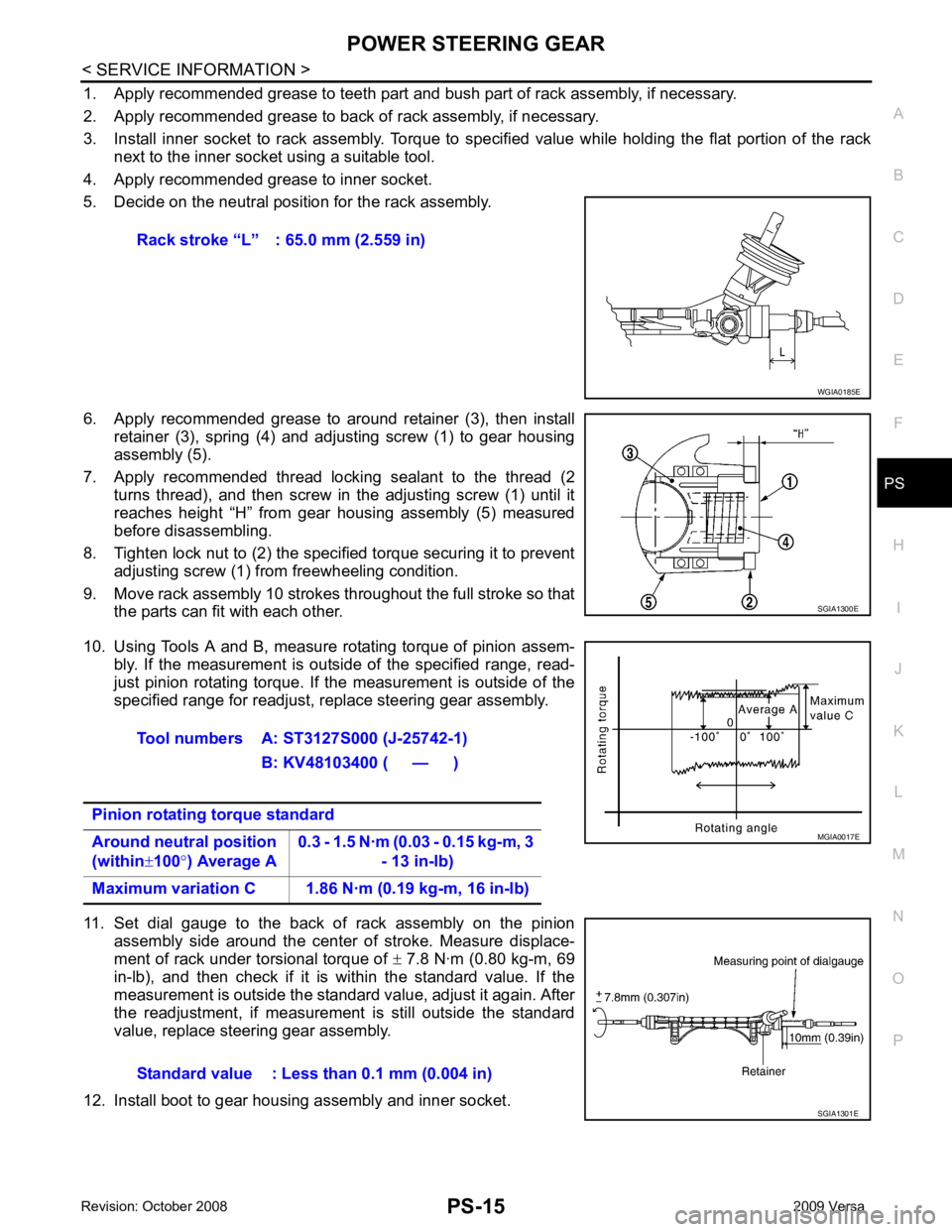
5. Decide on the neutral position for the rack assembly.
6. Apply recommended grease to around retainer (3), then install retainer (3), spring (4) and adjusting screw (1) to gear housing
assembly (5).
7. Apply recommended thread locking sealant to the thread (2 turns thread), and then screw in the adjusting screw (1) until it
reaches height “H” from gear housing assembly (5) measured
before disassembling.
8. Tighten lock nut to (2) the specified torque securing it to prevent adjusting screw (1) from freewheeling condition.
9. Move rack assembly 10 strokes throughout the full stroke so that the parts can fit with each other.
10. Using Tools A and B, measure rotating torque of pinion assem- bly. If the measurement is outside of the specified range, read-
just pinion rotating torque. If the measurement is outside of the
specified range for readjust, replace steering gear assembly.
11. Set dial gauge to the back of rack assembly on the pinion assembly side around the center of stroke. Measure displace-
ment of rack under torsional torque of ± 7.8 N·m (0.80 kg-m, 69
in-lb), and then check if it is within the standard value. If the
measurement is outside the standard value, adjust it again. After
the readjustment, if measurement is still outside the standard
value, replace steering gear assembly.
12. Install boot to gear housing assembly and inner socket. Rack stroke “L” : 65.0 mm (2.559 in)
Page 4072 of 4331
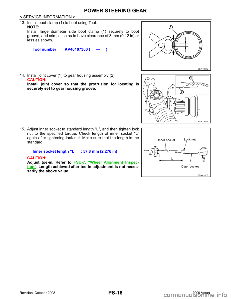
Wheel Alignment Inspec-
tion " . Length achieved after toe-in adjustment is not neces-
sarily the above value. Tool number : KV40107300 ( — ) SGIA1303E
Page 4073 of 4331
SERVICE DATA AND SPECIFICATIONS (SDS)
PS-17
< SERVICE INFORMATION >
C
D E
F
H I
J
K L
M A
B PS
N
O
P
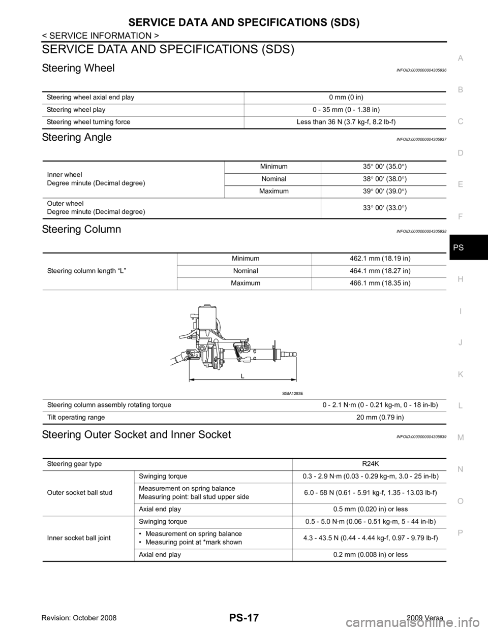
SERVICE DATA AND SPECIFICATIONS (SDS)
Steering Wheel INFOID:0000000004305936
Steering Angle INFOID:0000000004305937
Steering Column INFOID:0000000004305938
Steering Outer Socket and Inner Socket INFOID:0000000004305939
Steering wheel axial end play 0 mm (0 in)
Steering wheel play 0 - 35 mm (0 - 1.38 in)
Steering wheel turning force Less than 36 N (3.7 kg-f, 8.2 lb-f) Inner wheel
Degree minute (Decimal degree) Minimum 35
° 00 ′ (35.0 °)
Nominal 38 ° 00 ′ (38.0 °)
Maximum 39 ° 00 ′ (39.0 °)
Outer wheel
Degree minute (Decimal degree) 33
° 00 ′ (33.0 °) Steering column length “L”
Minimum 462.1 mm (18.19 in)
Nominal 464.1 mm (18.27 in)
Maximum 466.1 mm (18.35 in)
Steering column assembly rotating torque 0 - 2.1 N·m (0 - 0.21 kg-m, 0 - 18 in-lb)
Tilt operating range 20 mm (0.79 in)SGIA1293E
Steering gear type R24K
Outer socket ball stud Swinging torque 0.3 - 2.9 N·m (0.03 - 0.29 kg-m, 3.0 - 25 in-lb)
Measurement on spring balance
Measuring point: ball stud upper side 6.0 - 58 N (0.61 - 5.91 kg-f, 1.35 - 13.03 lb-f)
Axial end play 0.5 mm (0.020 in) or less
Inner socket ball joint Swinging torque 0.5 - 5.0 N·m (0.06 - 0.51 kg-m, 5 - 44 in-lb)
• Measurement on spring balance
• Measuring point at *mark shown 4.3 - 43.5 N (0.44 - 4.44 kg-f, 0.97 - 9.79 lb-f)
Axial end play 0.2 mm (0.008 in) or less