2009 NISSAN TIIDA Fuel pump relay
[x] Cancel search: Fuel pump relayPage 1397 of 4331

EC
NP
O
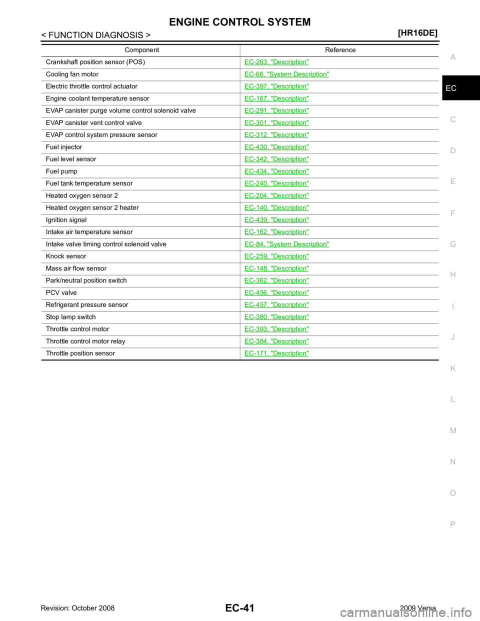
Crankshaft position sensor (POS)
EC-263, " Description "
Cooling fan motor
EC-66, " System Description "
Electric throttle control actuator
EC-397, " Description "
Engine coolant temperature sensor
EC-167, " Description "
EVAP canister purge volume control solenoid valve
EC-291, " Description "
EVAP canister vent control valve
EC-301, " Description "
EVAP control system pressure sensor
EC-312, " Description "
Fuel injector
EC-430, " Description "
Fuel level sensor
EC-342, " Description "
Fuel pump
EC-434, " Description "
Fuel tank temperature sensor
EC-240, " Description "
Heated oxygen sensor 2
EC-204, " Description "
Heated oxygen sensor 2 heater
EC-140, " Description "
Ignition signal
EC-439, " Description "
Intake air temperature sensor
EC-162, " Description "
Intake valve timing control solenoid valve
EC-84, " System Description "
Knock sensor
EC-259, " Description "
Mass air flow sensor
EC-148, " Description "
Park/neutral position switch
EC-362, " Description "
PCV valve
EC-456, " Description "
Refrigerant pressure sensor
EC-457, " Description "
Stop lamp switch
EC-380, " Description "
Throttle control motor
EC-393, " Description "
Throttle control motor relay
EC-384, " Description "
Throttle position sensor
EC-171, " Description "Component Reference
Page 1465 of 4331

EC
NP
O
Test Item
*: Leaving cooling fan OFF with CONSULT-III while engine is running may cause the engine to overheat.
DTC & SRT CONFIRMATION MODE
SRT STATUS Mode For details, refer to EC-90, " Diagnosis Description " .
SRT WORK SUPPORT Mode This mode enables a technician to drive a vehicle to set the SRT while monitoring the SRT status.
DTC WORK SUPPORT Mode TEST ITEM CONDITION JUDGMENT CHECK ITEM (REMEDY)
FUEL INJECTION • Engine: Return to the original
trouble condition
• Change the amount of fuel injec- tion using CONSULT-III. If trouble symptom disappears, see
CHECK ITEM. • Harness and connectors
• Fuel injector
• Air fuel ratio (A/F) sensor 1
IGNITION TIMING • Engine: Return to the original
trouble condition
• Timing light: Set
• Retard the ignition timing using
CONSULT-III. If trouble symptom disappears, see
CHECK ITEM. • Perform Idle Air Volume Learning.
POWER BALANCE • Engine: After warming up, idle
the engine.
• A/C switch OFF
• Selector lever: P or N position (A/ T), Neutral position (M/T)
• Cut off each fuel injector signal
one at a time using CONSULT-
III. Engine runs rough or dies.
• Harness and connectors
• Compression
• Fuel injector
• Power transistor
• Spark plug
• Ignition coil
COOLING FAN* • Ignition switch: ON
• Turn the cooling fan “LOW”, “HI”
and “OFF” using CONSULT-III. Cooling fan moves and stops.
• Harness and connectors
• IPDM E/R (Cooling fan relay)
• Cooling fan motor
ENG COOLANT
TEMP • Engine: Return to the original
trouble condition
• Change the engine coolant tem-
perature using CONSULT-III. If trouble symptom disappears, see
CHECK ITEM. • Harness and connectors
• Engine coolant temperature sen- sor
• Fuel injector
FUEL PUMP RELAY • Ignition switch: ON (Engine
stopped)
• Turn the fuel pump relay “ON”
and “OFF” using CONSULT-III
and listen to operating sound. Fuel pump relay makes the operat-
ing sound. • Harness and connectors
• Fuel pump relay
PURG VOL CONT/V • Engine: After warming up, run
engine at 1,500 rpm.
• Change the EVAP canister purge volume control solenoid
valve opening percent using
CONSULT-III. Engine speed changes according
to the opening percent. • Harness and connectors
• Solenoid valve
FUEL/T TEMP SEN • Change the fuel tank temperature using CONSULT-III.
VENT CONTROL/V • Ignition switch: ON (Engine
stopped)
• Turn solenoid valve “ON” and “OFF” using th e CONSULT-III
and listen to operating sound. Solenoid valve makes an operating
sound. • Harness and connectors
• Solenoid valve
V/T ASSIGN ANGLE • Engine: Return to the original
trouble condition
• Change intake valve timing us-
ing CONSULT-III. If trouble symptom disappears, see
CHECK ITEM. • Harness and connectors
• Intake valve timing control sole- noid valve
Page 1700 of 4331

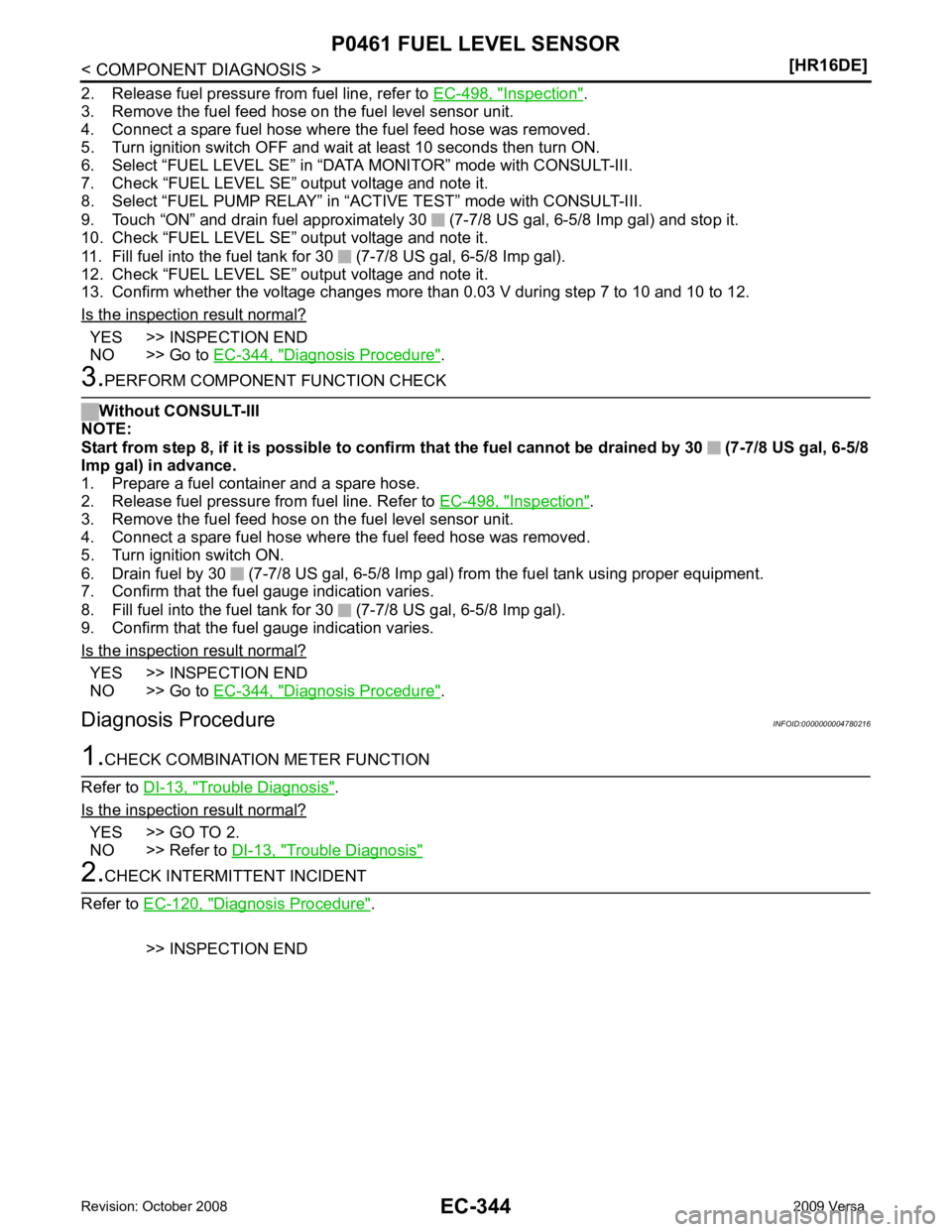
Inspection " .
3. Remove the fuel feed hose on the fuel level sensor unit.
4. Connect a spare fuel hose where the fuel feed hose was removed.
5. Turn ignition switch OFF and wait at least 10 seconds then turn ON.
6. Select “FUEL LEVEL SE” in “DAT A MONITOR” mode with CONSULT-III.
7. Check “FUEL LEVEL SE” output voltage and note it.
8. Select “FUEL PUMP RELAY” in “ACTIVE TEST” mode with CONSULT-III.
9. Touch “ON” and drain fuel approximately 30 (7-7/8 US gal, 6-5/8 Imp gal) and stop it.
10. Check “FUEL LEVEL SE” output voltage and note it.
11. Fill fuel into the fuel tank for 30 (7-7/8 US gal, 6-5/8 Imp gal).
12. Check “FUEL LEVEL SE” output voltage and note it.
13. Confirm whether the voltage changes more than 0.03 V during step 7 to 10 and 10 to 12.
Is the inspection result normal? YES >> INSPECTION END
NO >> Go to EC-344, " Diagnosis Procedure " .
Inspection " .
3. Remove the fuel feed hose on the fuel level sensor unit.
4. Connect a spare fuel hose where the fuel feed hose was removed.
5. Turn ignition switch ON.
6. Drain fuel by 30 (7-7/8 US gal, 6-5/8 Imp gal) from the fuel tank using proper equipment.
7. Confirm that the fuel gauge indication varies.
8. Fill fuel into the fuel tank for 30 (7-7/8 US gal, 6-5/8 Imp gal).
9. Confirm that the fuel gauge indication varies.
Is the inspection result normal? YES >> INSPECTION END
NO >> Go to EC-344, " Diagnosis Procedure " .
Diagnosis Procedure INFOID:0000000004780216Trouble Diagnosis " .
Is the inspection result normal? YES >> GO TO 2.
NO >> Refer to DI-13, " Trouble Diagnosis "
Diagnosis Procedure " .
>> INSPECTION END
Page 1790 of 4331

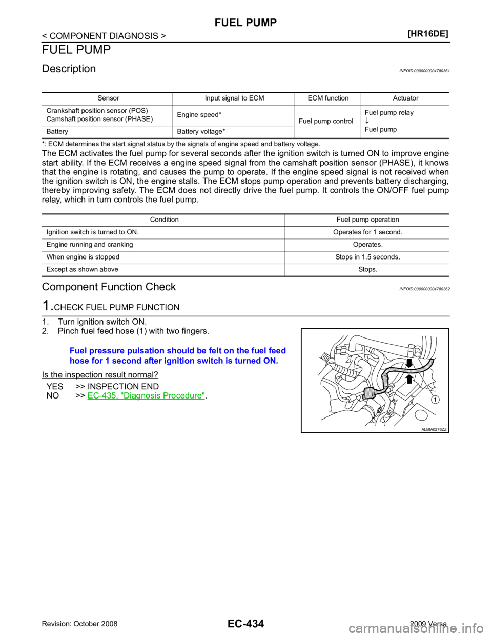
YES >> INSPECTION END
NO >> EC-435, " Diagnosis Procedure " .
Sensor Input signal to ECM ECM function Actuator
Crankshaft position sensor (POS)
Camshaft position sensor (PHASE) Engine speed*
Fuel pump controlFuel pump relay
↓
Fuel pump
Battery Battery voltage*
Condition Fuel pump operation
Ignition switch is turned to ON. Operates for 1 second.
Engine running and cranking Operates.
When engine is stopped Stops in 1.5 seconds.
Except as shown above Stops.
Page 1809 of 4331

EC
NP
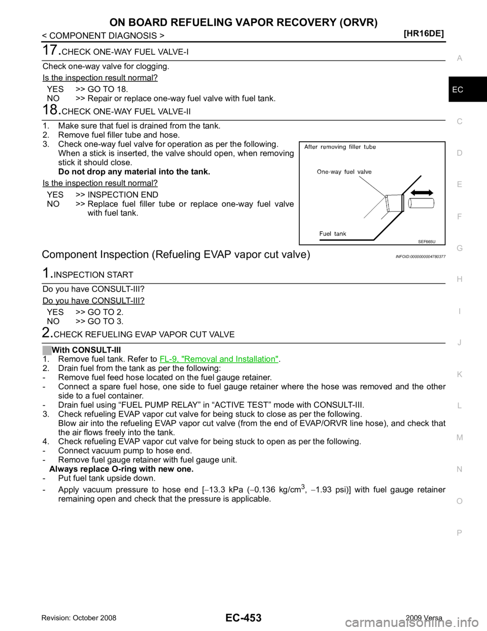
O YES >> GO TO 18.
NO >> Repair or replace one-way fuel valve with fuel tank. YES >> INSPECTION END
NO >> Replace fuel filler tube or replace one-way fuel valve
with fuel tank.
Component Inspection (Refuel ing EVAP vapor cut valve) INFOID:0000000004780377YES >> GO TO 2.
NO >> GO TO 3. Removal and Installation " .
2. Drain fuel from the tank as per the following:
- Remove fuel feed hose located on the fuel gauge retainer.
- Connect a spare fuel hose, one side to fuel gauge retainer where the hose was removed and the other
side to a fuel container.
- Drain fuel using “FUEL PUMP RELAY” in “ACTIVE TEST” mode with CONSULT-III.
3. Check refueling EVAP vapor cut valve for being stuck to close as per the following.
Blow air into the refueling EVAP vapor cut valv e (from the end of EVAP/ORVR line hose), and check that
the air flows freely into the tank.
4. Check refueling EVAP vapor cut valve for being stuck to open as per the following.
- Connect vacuum pump to hose end.
- Remove fuel gauge retainer with fuel gauge unit. Always replace O-ring with new one.
- Put fuel tank upside down.
- Apply vacuum pressure to hose end [ −13.3 kPa ( −0.136 kg/cm 3
, −1.93 psi)] with fuel gauge retainer
remaining open and check that the pressure is applicable.
Page 1821 of 4331
![NISSAN TIIDA 2009 Service Repair Manual EC
NP
O
9 P
EVAP canister purge volume
control solenoid valve [Engine is running]
• Idle speed
• Accelerator pedal: Not depressed even
slightly, after engine starting. BATTERY VOLTAGE
(11 - 14 V NISSAN TIIDA 2009 Service Repair Manual EC
NP
O
9 P
EVAP canister purge volume
control solenoid valve [Engine is running]
• Idle speed
• Accelerator pedal: Not depressed even
slightly, after engine starting. BATTERY VOLTAGE
(11 - 14 V](/manual-img/5/57398/w960_57398-1820.png)
EC
NP
O
9 P
EVAP canister purge volume
control solenoid valve [Engine is running]
• Idle speed
• Accelerator pedal: Not depressed even
slightly, after engine starting. BATTERY VOLTAGE
(11 - 14 V)
[Engine is running]
• Engine speed: About 2,000 rpm (More than 100 seconds after starting engine) BATTERY VOLTAGE
(11 - 14 V)
10 11 B
B ECM ground
[Engine is running]
• Idle speed Body ground
15 Y Throttle control motor relay [Ignition switch: OFF]
BATTERY VOLTAGE
(11 - 14 V)
[Ignition switch: ON] 0 - 1.0 V
17
18
21
22 R
LG
G
SB Ignition signal No. 1
Ignition signal No. 2
Ignition signal No. 4
Ignition signal No. 3 [Engine is running]
• Warm-up condition
• Idle speed NOTE:
The pulse cycle changes depending on rpm
at idle. 0 - 0.3 V
[Engine is running]
• Warm-up condition
• Engine speed: 2,500 rpm. 0.2 - 0.5 V
23 GR Fuel pump relay [Ignition switch: ON]
• For 1 second after turning ignition switch ON
[Engine is running] 0 - 1.0 V
[Ignition switch: ON]
• More than 1 second after turning ignition switch ON BATTERY VOLTAGE
(11 - 14 V)
TERMI-
NAL
NO. WIRE
COLOR ITEM CONDITION DATA (DC Voltage) PBIA9265J
Page 1892 of 4331
![NISSAN TIIDA 2009 Service Repair Manual EC-536< SERVICE INFOMATION >
[MR TYPE 1]
ON BOARD REFUELING VAPOR RECOVERY (ORVR)
1. Remove fuel tank. Refer to FL-9 .
2. Drain fuel from the tank as follows:
a. Remove fuel feed hose located on the NISSAN TIIDA 2009 Service Repair Manual EC-536< SERVICE INFOMATION >
[MR TYPE 1]
ON BOARD REFUELING VAPOR RECOVERY (ORVR)
1. Remove fuel tank. Refer to FL-9 .
2. Drain fuel from the tank as follows:
a. Remove fuel feed hose located on the](/manual-img/5/57398/w960_57398-1891.png)
EC-536< SERVICE INFOMATION >
[MR TYPE 1]
ON BOARD REFUELING VAPOR RECOVERY (ORVR)
1. Remove fuel tank. Refer to FL-9 .
2. Drain fuel from the tank as follows:
a. Remove fuel feed hose located on the fuel gauge retainer.
b. Connect a spare fuel hose, one side to fuel gauge retainer where the hose was removed and the other
side to a fuel container.
c. Drain fuel using “FUEL PUMP RELAY” in “ACTIVE TEST” mode with CONSULT-III.
3. Check refueling EVAP vapor cut valve for being stuck to close as follows. Blow air into the refueling EVAP vapor cut valv e (from the end of EVAP/ORVR line hose), and check that
the air flows freely into the tank.
4. Check refueling EVAP vapor cut valve for being stuck to open as follows.
a. Connect vacuum pump to hose end.
b. Remove fuel gauge retainer with fuel gauge unit. Always replace O-ring with new one.
c. Put fuel tank upside down.
d. Apply vacuum pressure to hose end [ −13.3 kPa ( −100 mmHg, −3.94 inHg)] with fuel gauge retainer
remaining open and check that the pressure is applicable.
Without CONSULT-III
1. Remove fuel tank. Refer to FL-9 .
2. Drain fuel from the tank as follows:
a. Remove fuel gauge retainer.
b. Drain fuel from the tank using a handy pump into a fuel container.
3. Check refueling EVAP vapor cut valve for being stuck to close as follows. Blow air into the refueling EVAP vapor cut valv e (from the end of EVAP/ORVR line hose), and check that
the air flows freely into the tank.
4. Check refueling EVAP vapor cut valve for being stuck to open as follows.
a. Connect vacuum pump to hose end. 1. Filler tube 2. Recirculation line 3. EVAP/ORVR line
4. Vacuum/pressure handy pump 5. Fuel tank BBIA0694E
Page 1955 of 4331
![NISSAN TIIDA 2009 Service Repair Manual TROUBLE DIAGNOSIS
EC-599
< SERVICE INFOMATION >
[MR TYPE 1] C
D E
F
G H
I
J
K L
M A EC
NP
O
15 Y Throttle control motor relay
[Ignition switch: OFF]
BATTERY VOLTAGE
(11 - 14V)
[Ignition switch: ON] 0 NISSAN TIIDA 2009 Service Repair Manual TROUBLE DIAGNOSIS
EC-599
< SERVICE INFOMATION >
[MR TYPE 1] C
D E
F
G H
I
J
K L
M A EC
NP
O
15 Y Throttle control motor relay
[Ignition switch: OFF]
BATTERY VOLTAGE
(11 - 14V)
[Ignition switch: ON] 0](/manual-img/5/57398/w960_57398-1954.png)
TROUBLE DIAGNOSIS
EC-599
< SERVICE INFOMATION >
[MR TYPE 1] C
D E
F
G H
I
J
K L
M A EC
NP
O
15 Y Throttle control motor relay
[Ignition switch: OFF]
BATTERY VOLTAGE
(11 - 14V)
[Ignition switch: ON] 0 - 1.0V
17
18
21
22 R
LG
G
SB Ignition signal No. 1
Ignition signal No. 2
Ignition signal No. 4
Ignition signal No. 3 [Engine is running]
• Warm-up condition
• Idle speed
NOTE:
The pulse cycle changes depending on rpm
at idle. 0 - 0.3V
[Engine is running]
• Warm-up condition
• Engine speed: 2,500 rpm. 0.2 - 0.5V
23 GR Fuel pump relay [Ignition switch: ON]
• For 1 second after turning ignition switch ON
[Engine is running] 0 - 1.0V
[Ignition switch: ON]
• More than 1 second after turning ignition switch ON BATTERY VOLTAGE
(11 - 14V)
25
29
30
31 V
Y
O
L Fuel injector No. 4
Fuel injector No. 3
Fuel injector No. 2
Fuel injector No. 1 [Engine is running]
• Warm-up condition
• Idle speed NOTE:
The pulse cycle changes depending on rpm
at idle. BATTERY VOLTAGE
(11 - 14V)
[Engine is running]
• Warm-up condition
• Engine speed: 2,000 rpm BATTERY VOLTAGE
(11 - 14V)
28 W EVAP canister vent control
valve [Ignition switch: ON] BATTERY VOLTAGE
(11 - 14V)
32 P ECM relay
(Self shut-off) [Engine is running]
[Ignition switch: OFF]
• For a few seconds after turning ignition switch OFF 0 - 1.0V
[Ignition switch: OFF]
• More than a few seconds after turning igni- tion switch OFF BATTERY VOLTAGE
(11 - 14V)
TERMI-
NAL
NO. WIRE
COLOR ITEM CONDITION DATA (DC Voltage) PBIA9265J
PBIA9266J
PBIB0529E
PBIA4943J