Page 76 of 4331

AT
N
O P
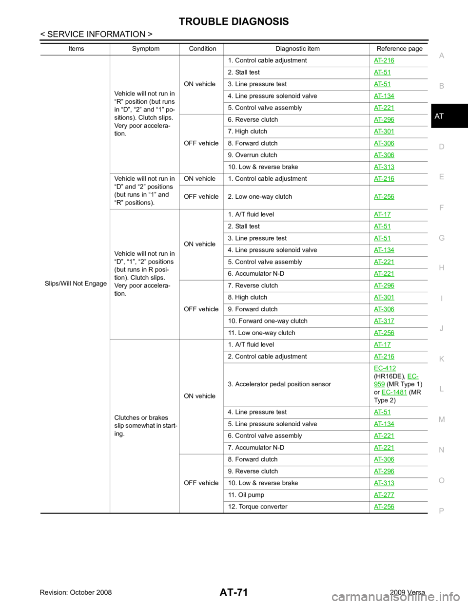
Slips/Will Not Engage
Vehicle will not run in
“R” position (but runs
in “D”, “2” and “1” po-
sitions). Clutch slips.
Very poor accelera-
tion. ON vehicle
1. Control cable adjustment
AT-216 2. Stall test
AT-51 3. Line pressure test
AT-51 4. Line pressure solenoid valve
AT-134 5. Control valve assembly
AT-221 OFF vehicle
6. Reverse clutch
AT-296 7. High clutch
AT-301 8. Forward clutch
AT-306 9. Overrun clutch
AT-306 10. Low & reverse brake
AT-313Vehicle will not run in
“D” and “2” positions
(but runs in “1” and
“R” positions). ON vehicle 1. Control cable adjustment
AT-216OFF vehicle 2. Low one-way clutch
AT-256Vehicle will not run in
“D”, “1”, “2” positions
(but runs in R posi-
tion). Clutch slips.
Very poor accelera-
tion. ON vehicle
1. A/T fluid level
AT-17 2. Stall test
AT-51 3. Line pressure test
AT-51 4. Line pressure solenoid valve
AT-134 5. Control valve assembly
AT-221 6. Accumulator N-D
AT-221 OFF vehicle
7. Reverse clutch
AT-296 8. High clutch
AT-301 9. Forward clutch
AT-306 10. Forward one-way clutch
AT-317 11. Low one-way clutch
AT-256Clutches or brakes
slip somewhat in start-
ing. ON vehicle1. A/T fluid level
AT-17 2. Control cable adjustment
AT-216 3. Accelerator pedal position sensor
EC-412
(HR16DE), EC- 959 (MR Type 1)
or EC-1481 (MR
Type 2)
4. Line pressure test AT-51 5. Line pressure solenoid valve
AT-134 6. Control valve assembly
AT-221 7. Accumulator N-D
AT-221 OFF vehicle
8. Forward clutch
AT-306 9. Reverse clutch
AT-296 10. Low & reverse brake
AT-313 11. Oil pump
AT-277 12. Torque converter
AT-256Items Symptom Condition Diagnostic item Reference page
Page 303 of 4331
Page 306 of 4331
AT
N
O P
7. Measure clearance between retaining plate and snap ring using
feeler gauge. If not within allowable limit, select proper retaining
plate. Refer to “Parts Information” for retaining plate selection.
8. Check operation of reverse clutch.
High Clutch INFOID:0000000004305521
COMPONENTS
DISASSEMBLY 1. Check operation of high clutch.
a. Apply compressed air into the oil hole (A) of input shaft assem- bly (high clutch drum) at the location as shown.
CAUTION:
Block the oil hole (A) on the opposite side with lint-free
cloth (B).
b. Check to see that retaining plate moves to snap ring.
c. If retaining plate does not contact snap ring: • High clutch piston seal might be damaged.Specified clearance
Standard and allowable limit: Refer to AT-375, " Clutches and Brakes " .
Page 308 of 4331

AT
N
O P
INSPECTION
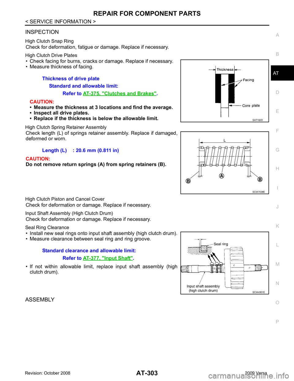
High Clutch Snap Ring Check for deformation, fatigue or damage. Replace if necessary.
High Clutch Drive Plates • Check facing for burns, cracks or damage. Replace if necessary.
• Measure thickness of facing.
CAUTION:
• Measure the thickness at 3 lo cations and find the average.
• Inspect all drive plates.
• Replace if the thickness is below the allowable limit.
High Clutch Spring Retainer Assembly Check length (L) of springs retainer assembly. Replace if damaged,
deformed or worn.
CAUTION:
Do not remove return springs (A) from spring retainers (B).
High Clutch Piston and Cancel Cover Check for deformation or damage. Replace if necessary.
Input Shaft Assembly (High Clutch Drum) Check for deformation or damage. Replace if necessary.
Seal Ring Clearance • Install new seal rings onto input shaft assembly (high clutch drum).
• Measure clearance between seal ring and ring groove.
• If not within allowable limit, replace input shaft assembly (high clutch drum).
ASSEMBLY Thickness of drive plate
Standard and allowable limit: Refer to AT-375, " Clutches and Brakes " .
Input Shaft " .
Page 310 of 4331
AT
N
O P
• HR16DE engine models
(1): Snap ring
(2): Retaining plate
(3): Drive plate
(4): Driven plate
Drive plate/Driven plate: 3/5
CAUTION:
Be careful with the orde r and direction of plates.
• MR18DE engine models
(1): Snap ring
(2): Retaining plate
(3): Drive plate
(4): Driven plate
(5): Driven plate
Drive plate/Driven plate: 4/7 (1+6)
CAUTION:
Be careful with the orde r and direction of plates.
5. Install snap ring using a flat-bladed screwdriver.
6. Set dial indicator (A) on retaining plate (1), and measure clear- ance between retaining plate (1) and snap ring (2). If not within
allowable limit, select proper retaining plate (1). Refer to “Parts
Information” for retaining plate selection.
7. Check operation of high clutch.
8. Install seal rings to input shaft assembly (high clutch drum). SCIA7703E
Clutches and Brakes " .
SCIA4890E
Page 314 of 4331

REPAIR FOR COMPONENT PARTS
AT-309
< SERVICE INFORMATION >
D
E
F
G H
I
J
K L
M A
B AT
N
O P
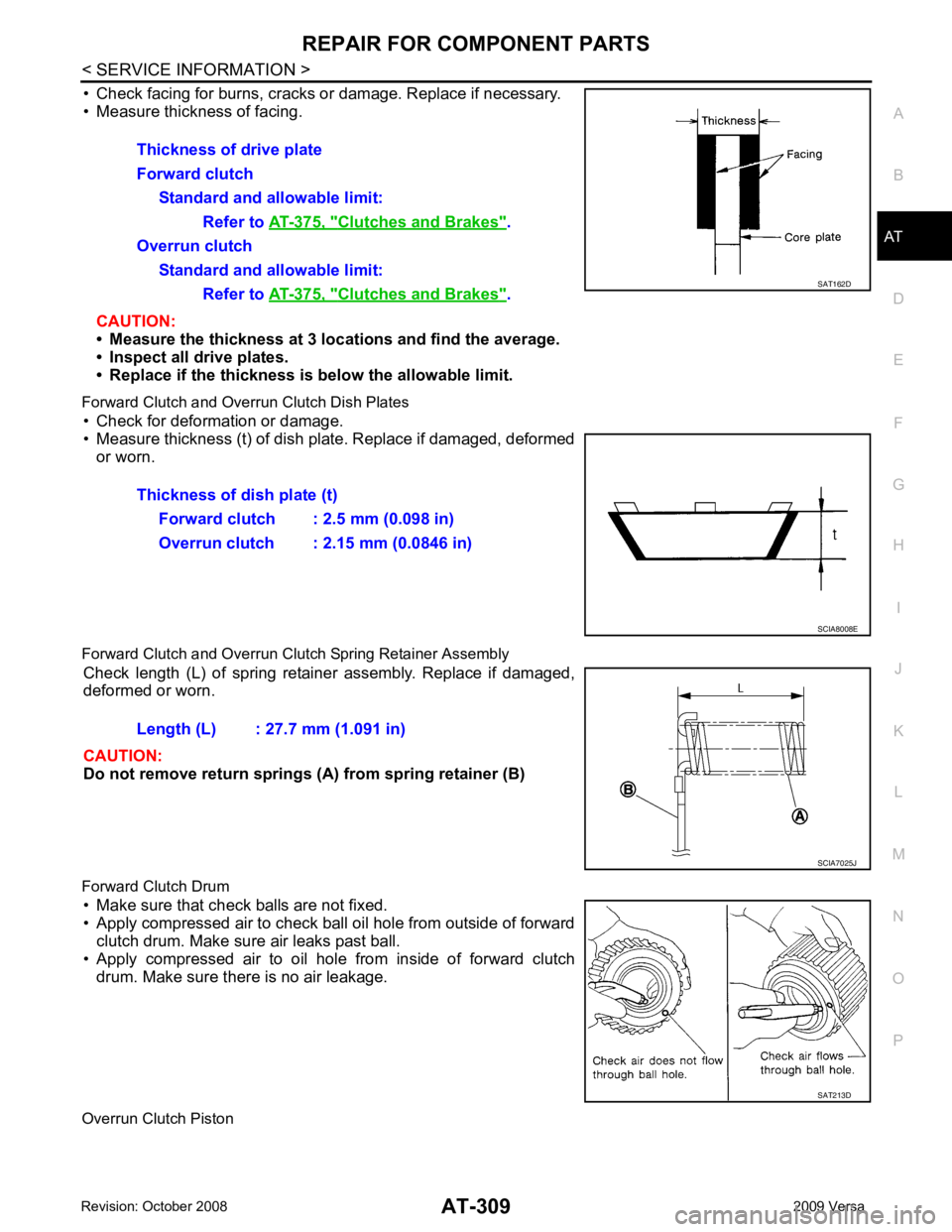
• Check facing for burns, cracks or
damage. Replace if necessary.
• Measure thickness of facing.
CAUTION:
• Measure the thickness at 3 lo cations and find the average.
• Inspect all drive plates.
• Replace if the thickness is below the allowable limit.
Forward Clutch and Overrun Clutch Dish Plates • Check for deformation or damage.
• Measure thickness (t) of dish plate. Replace if damaged, deformed or worn.
Forward Clutch and Overrun Clutch Spring Retainer Assembly Check length (L) of spring retainer assembly. Replace if damaged,
deformed or worn.
CAUTION:
Do not remove return springs (A) from spring retainer (B)
Forward Clutch Drum • Make sure that check balls are not fixed.
• Apply compressed air to check ball oil hole from outside of forward
clutch drum. Make sure air leaks past ball.
• Apply compressed air to oil hole from inside of forward clutch drum. Make sure there is no air leakage.
Overrun Clutch Piston Thickness of drive plate
Forward clutch Standard and allowable limit:
Refer to AT-375, " Clutches and Brakes " .
Overrun clutch Standard and allowable limit:
Refer to AT-375, " Clutches and Brakes " . SAT162D
Thickness of dish plate (t)
Forward clutch : 2.5 mm (0.098 in)
Overrun clutch : 2.15 mm (0.0846 in) SCIA8008E
Length (L) : 27.7 mm (1.091 in)
SCIA7025J
SAT213D
Page 317 of 4331
Clutches and Brakes " .
SCIA5992E
Clutches and Brakes " .
Page 320 of 4331
REPAIR FOR COMPONENT PARTS
AT-315
< SERVICE INFORMATION >
D
E
F
G H
I
J
K L
M A
B AT
N
O P
• Check facing for burns, cracks or
damage. Replace if necessary.
• Measure thickness of facing.
CAUTION:
• Measure the thickness at 3 lo cations and find the average.
• Inspect all drive plates.
• Replace if the thickness is below the allowable limit.
Low & Reverse Brake Dish Plates • Check for deformation or damage.
• Measure thickness (t) of dish plate. Replace if damaged, deformed
or worn.
Low & Reverse Brake Spring Retainer Assembly Check length (L) of spring retainer assembly. Replace if damaged,
deformed or worn.
CAUTION:
Do not remove return springs (A) from spring retainer (B)
ASSEMBLY 1. Install seal lip (1) and D-ring (2) on low & reverse brake piston (3).Thickness of drive plate
Standard and allowable limit:
Refer to AT-375, " Clutches and Brakes " .
SAT162D
Thickness of dish plate (t) : 2.93 mm (0.1154 in)
SCIA8008E
Length (L) : 26.3 mm (1.035 in)
SCIA7025J
SCIA6516J