2009 NISSAN TIIDA service indicator
[x] Cancel search: service indicatorPage 6 of 4331

AT
N
O P
CONTENTS
AUTOMATIC TRANSAXLE
SERVICE INFORMATION .. ..........................5
INDEX FOR DTC ............................................ .....5
Alphabetical Index ............................................... ......5
DTC No. Index .................................................... ......5
PRECAUTIONS .............................................. .....7
Precaution for Supplemental Restraint System
(SRS) "AIR BAG" and "SEAT BELT PRE-TEN-
SIONER" ............................................................. ......
7
Precaution Necessary fo r Steering Wheel Rota-
tion After Battery Disconnect ............................... ......
7
Precaution for On Board Diagnosis (OBD) System
of A/T and Engine ............................................... ......
8
Precaution ........................................................... ......8
Service Notice or Precaution ............................... ......9
PREPARATION .............................................. ....11
Special Service Tool ........................................... ....11
Commercial Service Tool .................................... ....14
A/T FLUID ....................................................... ....17
Checking A/T Fluid .............................................. ....17
Changing A/T Fluid ............................................. ....17
A/T Fluid Cooler Cleaning ................................... ....18
A/T CONTROL SYSTEM ................................ ....21
Cross-Sectional View ... ...........................................21
Shift Mechanism .................................................. ....22
TCM Function ...................................................... ....30
CAN Communication ........................................... ....31
Input/Output Signal of TCM ................................. ....31
Line Pressure Control .. ...........................................32
Shift Control ........................................................ ....33
Lock-up Control ................................................... ....34
Engine Brake Control (Ove rrun Clutch Control) ......35
Control Valve ....................................................... ....37
Centrifugal Cancel Mechanism ........................... ....37
ON BOARD DIAGNOSTIC (OBD) SYSTEM .. ....39
Introduction ......................................................... ....39
OBD-II Function for A/T System .......................... ....39 One or Two Trip Detection Logic of OBD-II .........
....39
OBD-II Diagnostic Trouble Code (DTC) .............. ....39
Malfunction Indicator Lamp (MIL) ............................41
TROUBLE DIAGNOSIS .................................... 42
DTC Inspection Priority Chart .............................. ....42
Fail-Safe .............................................................. ....42
How to Perform Trouble Diagnosis for Quick and
Accurate Repair ................................................... ....
43
A/T Electrical Parts Location ............................... ....49
Circuit Diagram .................................................... ....50
Inspections Before Trouble Diagnosis ................. ....51
Road Test ............................................................ ....55
Check Before Engine Is Started .......................... ....56
Check at Idle ........................................................ ....56
Cruise Test - Part 1 ............................................. ....58
Cruise Test - Part 2 ............................................. ....61
Cruise Test - Part 3 ............................................. ....62
Vehicle Speed at Which Gear Shifting Occurs .... ....64
Vehicle Speed at Which Lock-up Occurs/Releas-
es ......................................................................... ....
64
Symptom Chart .................................................... ....65
TCM Terminal and Refere nce Value .......................77
CONSULT-III Function (TRANSMISSION) .......... ....79
Diagnosis Procedure withou t CONSULT-III ............83
DTC U1000 CAN COMMUNICATION LINE ..... 88
Description ........................................................... ....88
On Board Diagnosis Logic ................................... ....88
Possible Cause .................................................... ....88
DTC Confirmation Procedure .............................. ....88
Wiring Diagram - AT - CAN ................................. ....89
Diagnosis Procedure ........................................... ....90
DTC P0705 PARK/NEUTRAL POSITION
(PNP) SWITCH .................................................. 91
Description ........................................................... ....91
CONSULT-III Reference Va lue in Data Monitor
Mode .................................................................... ....
91
On Board Diagnosis Logic ................................... ....91
Possible Cause .................................................... ....91
Page 14 of 4331
AT
N
O P
• The valve body contains precision parts and requires extreme care when parts are removed and serviced.
Place disassembled valve body parts in order for easier and proper assembly. Care will also prevent springs
and small parts from becoming scattered or lost.
• Properly installed valves, sleeves, plugs, etc. will slide along bores in valve body under their own weight.
• Before assembly, apply a coat of recommended ATF to all parts. Apply petroleum jelly to protect O-rings and
seals, or hold bearings and washers in pl ace during assembly. Do not use grease.
• Extreme care should be taken to avoid damage to O-rings, seals and gaskets when assembling.
• Clean or replace ATF cooler if excessive foreign material is found in oil pan or clogging strainer. Refer to AT-18, " A/T Fluid Cooler Cleaning " .
• After overhaul, refill the A/T with new ATF.
• When the A/T drain plug is removed, only some of the fluid is drained. Old A/T fluid will remain in torque con- verter and ATF cooling system.
Always follow the procedures under “Changing A/T Fluid” in the AT section when changing A/T fluid. Refer to
AT-17, " Changing A/T Fluid " ,
AT-17, " Checking A/T Fluid " .
Service Notice or Precaution INFOID:0000000004305292
ATF COOLER SERVICE If A/T fluid contains frictional material (clutches, bands, etc.), or if an A/T is repaired, overhauled, or replaced,
inspect and clean the A/T oil cooler mounted in the radiator or replace the radiator. Flush cooler lines using
cleaning solvent and compressed air after repair. Check Serv ice Bulletins for latest A/T oil cooler cleaning pro-
cedure. For radiator replacement, refer to CO-16, " Removal and Installation " (HR16DE engine models),
CO-38, " Removal and Installation " (MR18DE engine models).
TORQUE CONVERTER SERVICE The torque converter should be replaced under any of the following conditions:
• External leaks in the hub weld area.
• Converter hub is scored or damaged.
• Converter pilot is broken, damaged or fits poorly into crankshaft.
• Steel particles are found after flushing the cooler and cooler lines.
• Pump is damaged or steel particles are found in the converter.
• Vehicle has TCC shudder and/or no TCC apply. Replace only after all hydraulic and electrical diagnoses
have been made. (Converter clutch material may be glazed.)
• Converter is contaminated with engi ne coolant containing antifreeze.
• Internal malfunction of stator roller clutch.
• Heavy clutch debris due to overheating (blue converter).
• Steel particles or clutch lining material found in flui d filter or on magnet when no internal parts in unit are
worn or damaged — indicates that lining material came from converter.
The torque converter should not be replaced if:
• The fluid has an odor, is discolored, and there is no evidence of metal or clutch facing particles.
• The threads in one or more of the converter bolt holes are damaged.
• A/T malfunction did not display evidence of damaged or worn internal parts, steel particles or clutch plate lin-
ing material in unit and inside the fluid filter.
• Vehicle has been exposed to high mileage (only). The e xception may be where the torque converter clutch
dampener plate lining has seen excess wear by vehicles operated in heavy and/or constant traffic, such as
taxi, delivery or police use.
OBD-II SELF-DIAGNOSIS • A/T self-diagnosis is performed by the TCM in combination with the ECM. The results can be read through the blinking pattern of the OD OFF indicator lamp or the malfunction indicator lamp (MIL). Refer to the table
on AT-83, " Diagnosis Procedure without CONSULT-III " for the indicator used to display each self-diagnostic
result.
• The self-diagnostic results indicated by the MIL ar e automatically stored in both the ECM and TCM memo-
ries.
Always perform the procedure “HOW TO ERASE DTC” on AT-39, " OBD-II Diagnostic Trouble Code
(DTC) " to complete the repair and avo
id unnecessary blinking of the MIL.
• The following self-diagnostic items can be detected us ing ECM self-diagnostic results mode* only when the
OD OFF indicator lamp does not indicate any malfunctions.
- PNP switch
- A/T 1st, 2nd, 3rd, or 4th gear function
*: For details of OBD-II, refer to AT-39 .
Page 66 of 4331
TROUBLE DIAGNOSIS
AT-61
< SERVICE INFORMATION >
D
E
F
G H
I
J
K L
M A
B AT
N
O P
• Continue “Road Test”. 8.
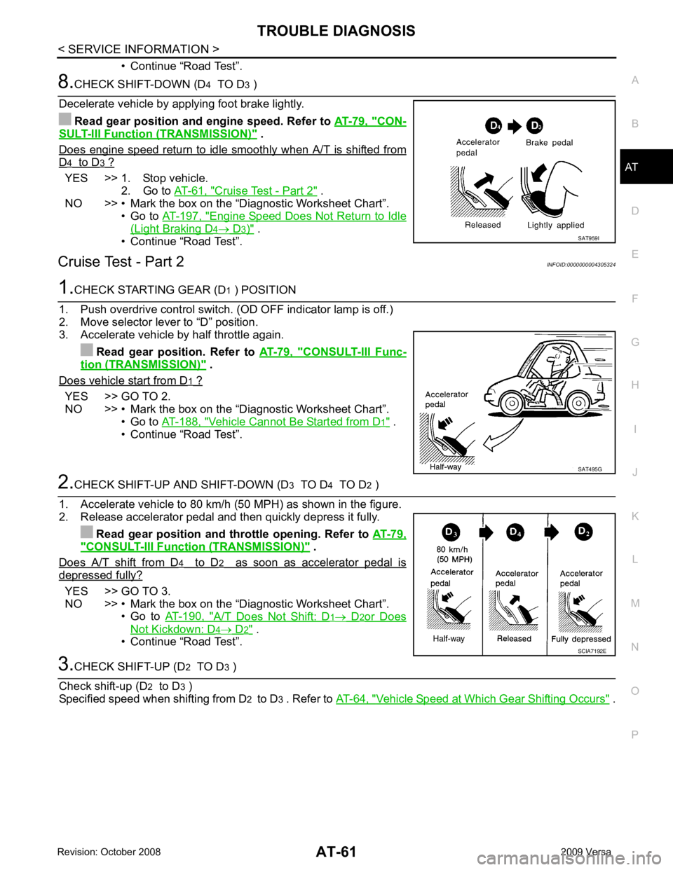
CHECK SHIFT-DOWN (D 4 TO D 3 )
Decelerate vehicle by applying foot brake lightly. Read gear position and engine speed. Refer to AT-79, " CON-
SULT-III Functi
on (TRANSMISSION) " .
Does engine speed return to idle smoothly when A/T is shifted from D 4 to D 3 ?
YES >> 1. Stop vehicle.
2. Go to AT-61, " Cruise Test - Part 2 " .
NO >> • Mark the box on the “D iagnostic Worksheet Chart”.
• Go to AT-197, " Engine Speed Does Not Return to Idle
(Light Braking D 4 → D 3 ) " .
• Continue “Road Test”.
Cruise Test - Part 2 INFOID:00000000043053241.
CHECK STARTING GEAR (D 1 ) POSITION
1. Push overdrive control switch. (OD OFF indicator lamp is off.)
2. Move selector lever to “D” position.
3. Accelerate vehicle by half throttle again.
Read gear position. Refer to AT-79, " CONSULT-III Func-
tion (TRANSMISSION) " .
Does vehicle start from D 1 ?
YES >> GO TO 2.
NO >> • Mark the box on the “D iagnostic Worksheet Chart”.
• Go to AT-188, " Vehicle Cannot Be Started from D 1 " .
• Continue “Road Test”. 2.
CHECK SHIFT-UP AND SHIFT-DOWN (D 3 TO D 4 TO D 2 )
1. Accelerate vehicle to 80 km/h (50 MPH) as shown in the figure.
2. Release accelerator pedal and then quickly depress it fully.
Read gear position and th rottle opening. Refer to AT-79," CONSULT-III Function (TRANSMISSION) " .
Does A/T shift from D 4 to D 2 as soon as accelerator pedal is
depressed fully?
YES >> GO TO 3.
NO >> • Mark the box on the “D iagnostic Worksheet Chart”.
• Go to AT-190, " A/T Does Not Shift: D 1 → D 2 or Does
Not Kickdown: D 4 → D 2 " .
• Continue “Road Test”. 3.
CHECK SHIFT-UP (D 2 TO D 3 )
Check shift-up (D 2 to D 3 )
Specified speed when shifting from D 2 to D 3 . Refer to AT-64, " Vehicle Speed at Which Gear Shifting Occurs " .SAT959I
SAT495G
SCIA7192E
Page 89 of 4331
AT-84< SERVICE INFORMATION >
TROUBLE DIAGNOSIS
Description
If a malfunction occurs in electrical system, turning igni tion switch ON will illuminate OD OFF indicator lamp for
2 seconds. To detect a malfunction, entering a self-diagnosis start signal retrieves information on malfunctions
from memory and indicates malfunction by blinking OD OFF indicator lamp.
Diagnostic Procedure 1.
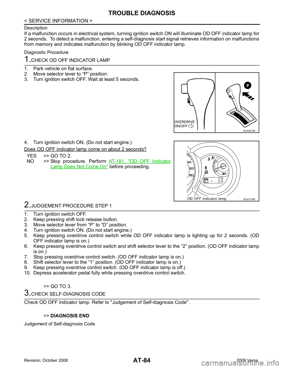
CHECK OD OFF INDICATOR LAMP
1. Park vehicle on flat surface.
2. Move selector lever to “P” position.
3. Turn ignition switch OFF. Wait at least 5 seconds.
4. Turn ignition switch ON. (Do not start engine.)
Does OD OFF indicator lamp come on about 2 seconds? YES >> GO TO 2.
NO >> Stop procedure. Perform AT-181, " OD OFF Indicator
Lamp Does Not Come On " before proceeding.
2.
JUDGEMENT PROCEDURE STEP 1
1. Turn ignition switch OFF.
2. Keep pressing shift lock release button.
3. Move selector lever from “P” to “D” position.
4. Turn ignition switch ON. (Do not start engine.)
5. Keep pressing overdrive control switch while OD OF F indicator lamp is lighting up for 2 seconds. (OD
OFF indicator lamp is on.)
6. Keep pressing overdrive control switch and shift select or lever to the “2” position. (OD OFF indicator lamp
is on.)
7. Stop pressing overdrive control switch. (OD OFF indicator lamp is on.)
8. Shift selector lever to the “1” position. (OD OFF indicator lamp is on.)
9. Keep pressing overdrive control switch. (OD OFF indicator lamp is off.)
10. Depress accelerator pedal fully while pressing overdrive control switch.
>> GO TO 3. 3.
CHECK SELF-DIAGNOSIS CODE
Check OD OFF indicator lamp. Refer to "Judgement of Self-diagnosis Code" .
>>DIAGNOSIS END
Judgement of Self-diagnosis Code SCIA5472E
SCIA7140E
Page 187 of 4331
AT-182< SERVICE INFORMATION >
TROUBLE DIAGNOSIS FOR SYMPTOMS
OD OFF indicator lamp does not come on for about 2 seconds when turning ignition switch to ON.
DIAGNOSTIC PROCEDURE 1.
CHECK CAN COMMUNICATION LINE
Perform self-diagnosis. Refer to AT-79, " CONSULT-III Function (TRANSMISSION) " .
Is a malfunction in CAN communication indicated in the results? YES >> Check CAN communication line. Refer to
AT-88 .
NO >> GO TO 2. 2.
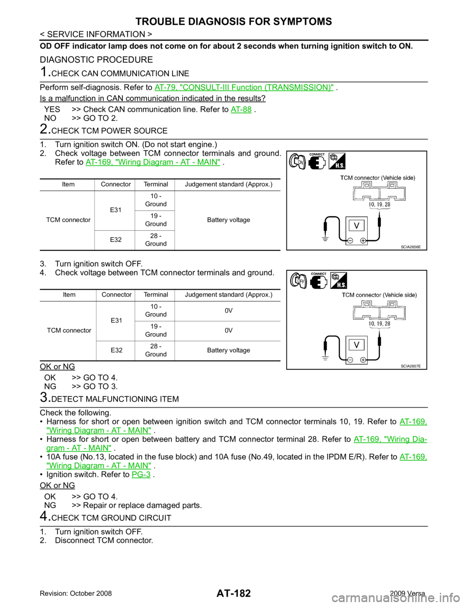
CHECK TCM POWER SOURCE
1. Turn ignition switch ON. (Do not start engine.)
2. Check voltage between TCM connector terminals and ground.
Refer to AT-169, " Wiring Diagram - AT - MAIN " .
3. Turn ignition switch OFF.
4. Check voltage between TCM connector terminals and ground.
OK or NG OK >> GO TO 4.
NG >> GO TO 3. 3.
DETECT MALFUNCTIONING ITEM
Check the following.
• Harness for short or open between ignition switch and TCM connector terminals 10, 19. Refer to AT-169," Wiring Diagram - AT - MAIN " .
• Harness for short or open between battery and TCM connector terminal 28. Refer to AT-169, " Wiring Dia-
gram - AT - MAIN " .
• 10A fuse (No.13, located in the fuse block) and 10A fuse (No.49, located in the IPDM E/R). Refer to AT-169," Wiring Diagram - AT - MAIN " .
• Ignition switch. Refer to PG-3 .
OK or NG OK >> GO TO 4.
NG >> Repair or replace damaged parts. 4.
CHECK TCM GROUND CIRCUIT
1. Turn ignition switch OFF.
2. Disconnect TCM connector. Item Connector Terminal Judgement standard (Approx.)
TCM connector E3110 -
Ground
Battery voltage
19 -
Ground
E32 28 -
Ground SCIA2656E
Item Connector Terminal Judgement standard (Approx.)
TCM connector E3110 -
Ground 0V
19 -
Ground 0V
E32 28 -
Ground Battery voltage SCIA2657E
Page 207 of 4331
AT-202< SERVICE INFORMATION >
TROUBLE DIAGNOSIS FOR SYMPTOMS
- Shift valve A
- Shift solenoid valve A
- Overrun clutch control valve
- Overrun clutch solenoid valve
3. Disassemble A/T. Refer to AT-256, " Disassembly " .
4. Check the following items:
- Servo piston assembly
- Brake band
OK or NG OK >> GO TO 7.
NG >> Repair or replace damaged parts. 7.
CHECK SYMPTOM
Check again. Refer to AT-62, " Cruise Test - Part 3 " .
OK or NG OK >>
INSPECTION END
NG >> GO TO 8. 8.
CHECK TCM
1. Check TCM input/output signals. Refer to AT-77, " TCM Terminal and Reference Value " .
2. If NG, recheck TCM pin terminals for damage or loose connection with harness connector.
OK or NG OK >>
INSPECTION END
NG >> Repair or replace damaged parts.
Vehicle Does Not Decele rate by Engine Brake INFOID:0000000004305490
SYMPTOM:
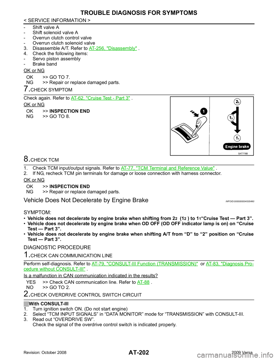
• Vehicle does not decelerate by engi ne brake when shifting from 22 (1 2 ) to 1 1“Cruise Test — Part 3”.
• Vehicle does not decelerate by engine brake when OD OFF (OD OFF indicator lamp is on) on “Cruise
Test — Part 3”.
• Vehicle does not decelerate by engi ne brake when shifting A/T from “D” to “2” position on “Cruise
Test — Part 3”.
DIAGNOSTIC PROCEDURE 1.
CHECK CAN COMMUNICATION LINE
Perform self-diagnosis. Refer to AT-79, " CONSULT-III Functi
on (TRANSMISSION) " or
AT-83, " Diagnosis Pro-
cedure without CONSULT-III " .
Is a malfunction in CAN communication indicated in the results? YES >> Check CAN communication line. Refer to
AT-88 .
NO >> GO TO 2. 2.
CHECK OVERDRIVE CONTROL SWITCH CIRCUIT
With CONSULT-III
1. Turn ignition switch ON. (Do not start engine)
2. Select “TCM INPUT SIGNALS” in “DATA MONITO R” mode for “TRANSMISSION” with CONSULT-III.
3. Read out “OVERDRIVE SW”. Check the signal of the overdrive c ontrol switch is indicated properly. SAT778B
Page 354 of 4331
ASSEMBLY
AT-349
< SERVICE INFORMATION >
D
E
F
G H
I
J
K L
M A
B AT
N
O P
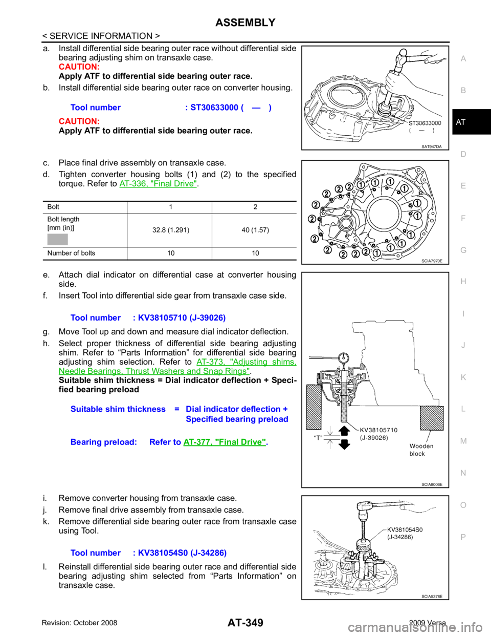
a. Install differential side bearing outer race without differential side
bearing adjusting shim on transaxle case.
CAUTION:
Apply ATF to differential side bearing outer race.
b. Install differential side bearing outer race on converter housing.
CAUTION:
Apply ATF to differential side bearing outer race.
c. Place final drive assembly on transaxle case.
d. Tighten converter housing bolts (1) and (2) to the specified torque. Refer to AT-336, " Final Drive " .
e. Attach dial indicator on differential case at converter housing side.
f. Insert Tool into differential side gear from transaxle case side.
g. Move Tool up and down and measure dial indicator deflection.
h. Select proper thickness of differential side bearing adjusting shim. Refer to “Parts Information” for differential side bearing
adjusting shim selection. Refer to AT-373, " Adjusting shims,
Needle Bearings, Thrust Washers and Snap Rings " .
Suitable shim thickness = Dial indicator deflection + Speci-
fied bearing preload
i. Remove converter housing from transaxle case.
j. Remove final drive assembly from transaxle case.
k. Remove differential side bearing outer race from transaxle case using Tool.
l. Reinstall differential side bearing outer race and differential side bearing adjusting shim selected from “Parts Information” on
transaxle case. Tool number : ST30633000 ( — ) SAT947DA
Bolt 1 2
Bolt length
[mm (in)] 32.8 (1.291) 40 (1.57)
Number of bolts 10 10 SCIA7970E
Tool number : KV38105710 (J-39026)
Suitable shim thickness = D ial indicator deflection +
Specified bearing preload
Bearing preload: Refer to AT-377, " Final Drive " .
SCIA8006E
Tool number : KV381054S0 (J-34286)
SCIA5378E
Page 499 of 4331
BL-38< SERVICE INFORMATION >
POWER DOOR LOCK SYSTEM
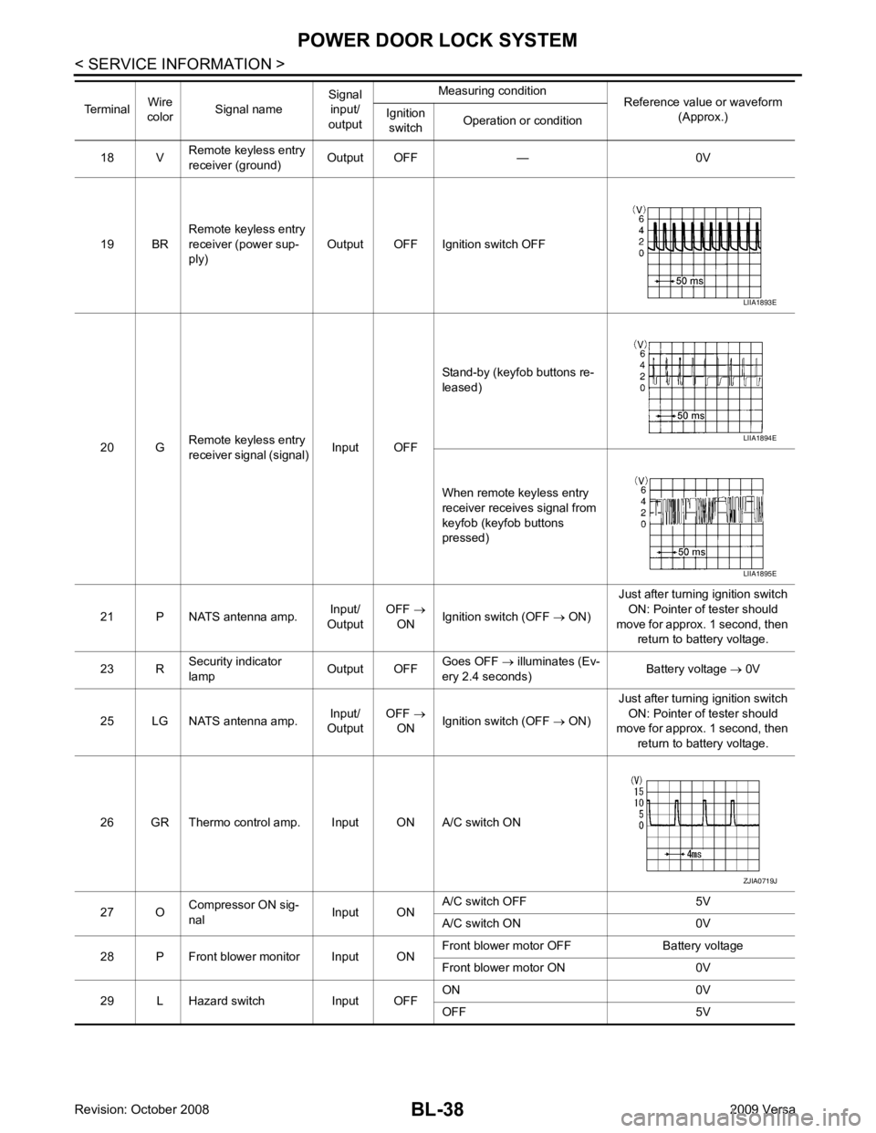
18 V Remote keyless entry
receiver (ground) Output OFF — 0V
19 BR Remote keyless entry
receiver (power sup-
ply) Output OFF Ignition switch OFF
20 G Remote keyless entry
receiver signal (signal) Input OFFStand-by (keyfob buttons re-
leased)
When remote keyless entry
receiver receives signal from
keyfob (keyfob buttons
pressed)
21 P NATS antenna amp. Input/
Output OFF
→
ON Ignition switch (OFF
→ ON) Just after turning ignition switch
ON: Pointer of tester should
move for approx. 1 second, then return to battery voltage.
23 R Security indicator
lamp Output OFFGoes OFF
→ illuminates (Ev-
ery 2.4 seconds) Battery voltage
→ 0V
25 LG NATS antenna amp. Input/
Output OFF
→
ON Ignition switch (OFF
→ ON) Just after turning ignition switch
ON: Pointer of tester should
move for approx. 1 second, then
return to battery voltage.
26 GR Thermo control amp. Input ON A/C switch ON
27 O Compressor ON sig-
nal Input ONA/C switch OFF 5V
A/C switch ON 0V
28 P Front blower monitor Input ON Front blower motor OFF Battery voltage
Front blower motor ON 0V
29 L Hazard switch Input OFF ON 0V
OFF 5V
Terminal
Wire
color Signal name Signal
input/
output Measuring condition
Reference value or waveform
(Approx.)
Ignition
switch Operation or condition LIIA1893E
LIIA1894E
LIIA1895E
ZJIA0719J