2009 NISSAN TIIDA service indicator
[x] Cancel search: service indicatorPage 663 of 4331
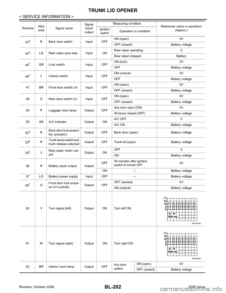
BL-202< SERVICE INFORMATION >
TRUNK LID OPENER
43 5
R Back door switch Input OFF ON (open) 0V
OFF (closed) Ba ttery voltage
44 5
LG Rear wiper auto stop Input ON Rear wiper operating 0
Rear wiper stopped Battery
45 7
GR Lock switch Input OFF ON (lock) 0V
OFF Battery voltage
46 7
L Unlock switch Input OFF ON (unlock) 0V
OFF Battery voltage
47 BR Front door switch LH Input OFF ON (open) 0V
OFF (closed) Ba ttery voltage
48 O Rear door switch LH Input OFF ON (open) 0V
OFF (closed) Ba ttery voltage
49 P Luggage room lamp Output OFF Any door open (ON) 0V
All doors closed (OFF) Battery voltage
50 SB A/C indicator Output ON A/C OFF 0
A/C ON Battery voltage
53 5
RBack door lock assem-
bly (actuator) Output OFF Back door (open) Battery voltage
53 6
RTrunk lamp switch and
trunk release solenoid Output OFF Trunk lid (open) Battery voltage
55 5
VRear wiper motor out-
put Output ONOFF 0
ON Battery voltage
56 R Battery saver output Output OFF
30 minutes after ignition
switch is turned OFF 0V
ON — Battery voltage
57 LG Battery power supply Input OFF — Battery voltage
59 7
GFront door lock actua-
tor LH (unlock) Output OFFOFF (neutral) 0V
ON (unlock) Battery voltage
60 V Turn signal (left) Output ON Turn left ON
61 W Turn signal (right) Output ON Turn right ON
63 BR Interior room lamp Output OFF Any door
switch ON (open) 0V
OFF (closed) Battery voltage
Terminal
Wire
color Signal name Signal
input/
output Measuring condition
Reference value or waveform
(Approx.)
Ignition
switch Operation or condition SKIA3009J
SKIA3009J
Page 689 of 4331
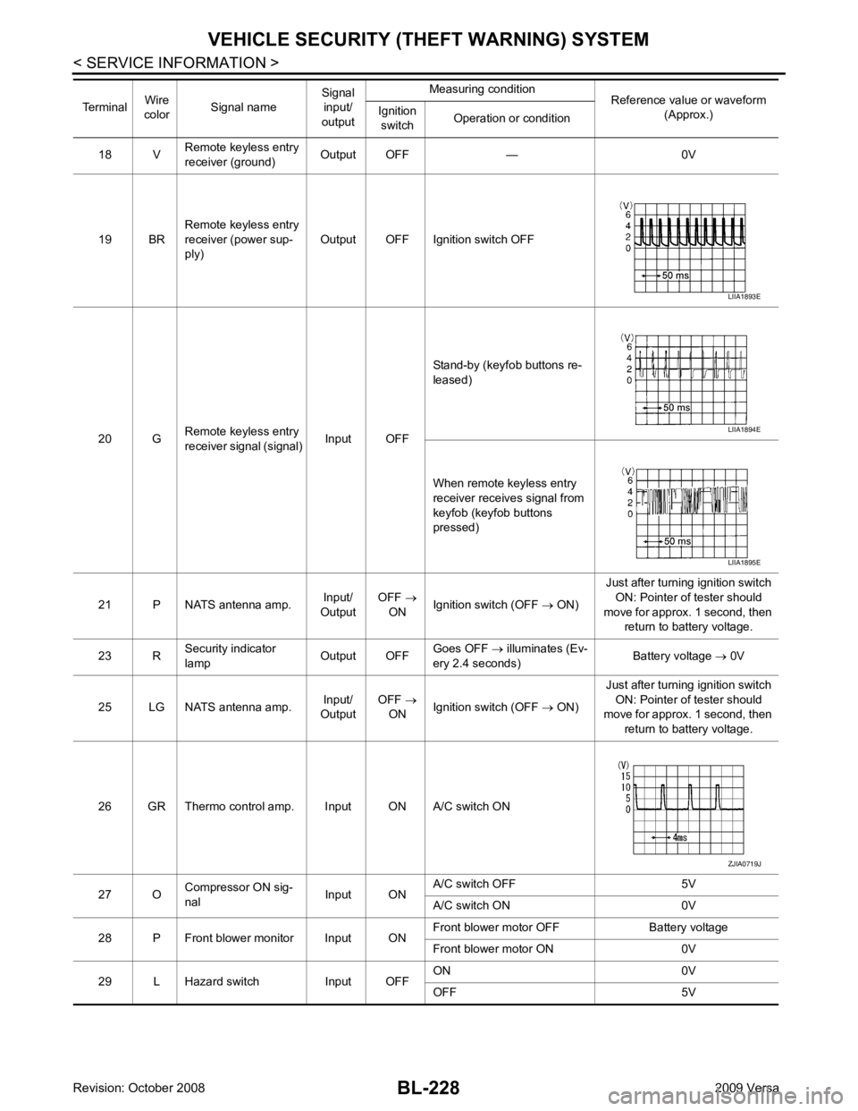
BL-228< SERVICE INFORMATION >
VEHICLE SECURITY (T
HEFT WARNING) SYSTEM
18 V Remote keyless entry
receiver (ground) Output OFF — 0V
19 BR Remote keyless entry
receiver (power sup-
ply) Output OFF Ignition switch OFF
20 G Remote keyless entry
receiver signal (signal) Input OFFStand-by (keyfob buttons re-
leased)
When remote keyless entry
receiver receives signal from
keyfob (keyfob buttons
pressed)
21 P NATS antenna amp. Input/
Output OFF
→
ON Ignition switch (OFF
→ ON) Just after turning ignition switch
ON: Pointer of tester should
move for approx. 1 second, then return to battery voltage.
23 R Security indicator
lamp Output OFFGoes OFF
→ illuminates (Ev-
ery 2.4 seconds) Battery voltage
→ 0V
25 LG NATS antenna amp. Input/
Output OFF
→
ON Ignition switch (OFF
→ ON) Just after turning ignition switch
ON: Pointer of tester should
move for approx. 1 second, then
return to battery voltage.
26 GR Thermo control amp. Input ON A/C switch ON
27 O Compressor ON sig-
nal Input ONA/C switch OFF 5V
A/C switch ON 0V
28 P Front blower monitor Input ON Front blower motor OFF Battery voltage
Front blower motor ON 0V
29 L Hazard switch Input OFF ON 0V
OFF 5V
Terminal
Wire
color Signal name Signal
input/
output Measuring condition
Reference value or waveform
(Approx.)
Ignition
switch Operation or condition LIIA1893E
LIIA1894E
LIIA1895E
ZJIA0719J
Page 691 of 4331
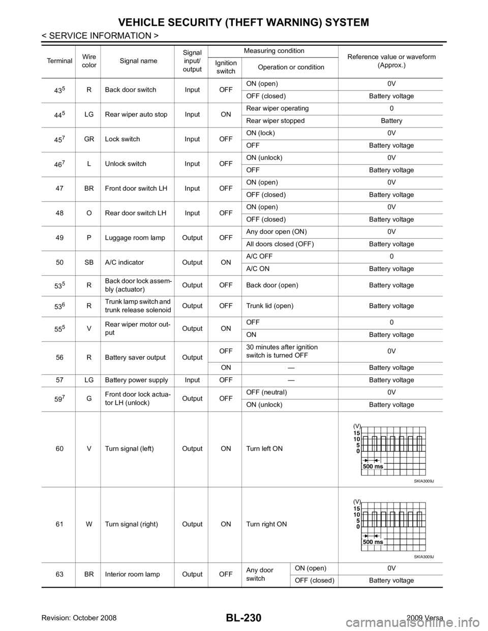
BL-230< SERVICE INFORMATION >
VEHICLE SECURITY (T
HEFT WARNING) SYSTEM
43 5
R Back door switch Input OFF ON (open) 0V
OFF (closed) Ba ttery voltage
44 5
LG Rear wiper auto stop Input ON Rear wiper operating 0
Rear wiper stopped Battery
45 7
GR Lock switch Input OFF ON (lock) 0V
OFF Battery voltage
46 7
L Unlock switch Input OFF ON (unlock) 0V
OFF Battery voltage
47 BR Front door switch LH Input OFF ON (open) 0V
OFF (closed) Ba ttery voltage
48 O Rear door switch LH Input OFF ON (open) 0V
OFF (closed) Ba ttery voltage
49 P Luggage room lamp Output OFF Any door open (ON) 0V
All doors closed (OFF) Battery voltage
50 SB A/C indicator Output ON A/C OFF 0
A/C ON Battery voltage
53 5
RBack door lock assem-
bly (actuator) Output OFF Back door (open) Battery voltage
53 6
RTrunk lamp switch and
trunk release solenoid Output OFF Trunk lid (open) Battery voltage
55 5
VRear wiper motor out-
put Output ONOFF 0
ON Battery voltage
56 R Battery saver output Output OFF
30 minutes after ignition
switch is turned OFF 0V
ON — Battery voltage
57 LG Battery power supply Input OFF — Battery voltage
59 7
GFront door lock actua-
tor LH (unlock) Output OFFOFF (neutral) 0V
ON (unlock) Battery voltage
60 V Turn signal (left) Output ON Turn left ON
61 W Turn signal (right) Output ON Turn right ON
63 BR Interior room lamp Output OFF Any door
switch ON (open) 0V
OFF (closed) Battery voltage
Terminal
Wire
color Signal name Signal
input/
output Measuring condition
Reference value or waveform
(Approx.)
Ignition
switch Operation or condition SKIA3009J
SKIA3009J
Page 714 of 4331
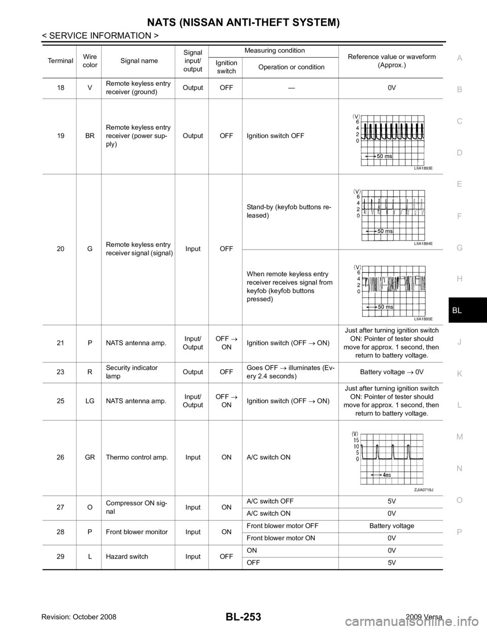
NATS (NISSAN ANTI-THEFT SYSTEM)
BL-253
< SERVICE INFORMATION >
C
D E
F
G H
J
K L
M A
B BL
N
O P
18 V
Remote keyless entry
receiver (ground) Output OFF — 0V
19 BR Remote keyless entry
receiver (power sup-
ply) Output OFF Ignition switch OFF
20 G Remote keyless entry
receiver signal (signal) Input OFFStand-by (keyfob buttons re-
leased)
When remote keyless entry
receiver receives signal from
keyfob (keyfob buttons
pressed)
21 P NATS antenna amp. Input/
Output OFF
→
ON Ignition switch (OFF
→ ON) Just after turning ignition switch
ON: Pointer of tester should
move for approx. 1 second, then return to battery voltage.
23 R Security indicator
lamp Output OFFGoes OFF
→ illuminates (Ev-
ery 2.4 seconds) Battery voltage
→ 0V
25 LG NATS antenna amp. Input/
Output OFF
→
ON Ignition switch (OFF
→ ON) Just after turning ignition switch
ON: Pointer of tester should
move for approx. 1 second, then
return to battery voltage.
26 GR Thermo control amp. Input ON A/C switch ON
27 O Compressor ON sig-
nal Input ONA/C switch OFF 5V
A/C switch ON 0V
28 P Front blower monitor Input ON Front blower motor OFF Battery voltage
Front blower motor ON 0V
29 L Hazard switch Input OFF ON 0V
OFF 5V
Terminal
Wire
color Signal name Signal
input/
output Measuring condition
Reference value or waveform
(Approx.)
Ignition
switch Operation or condition LIIA1893E
LIIA1894E
LIIA1895E
ZJIA0719J
Page 716 of 4331
NATS (NISSAN ANTI-THEFT SYSTEM)
BL-255
< SERVICE INFORMATION >
C
D E
F
G H
J
K L
M A
B BL
N
O P
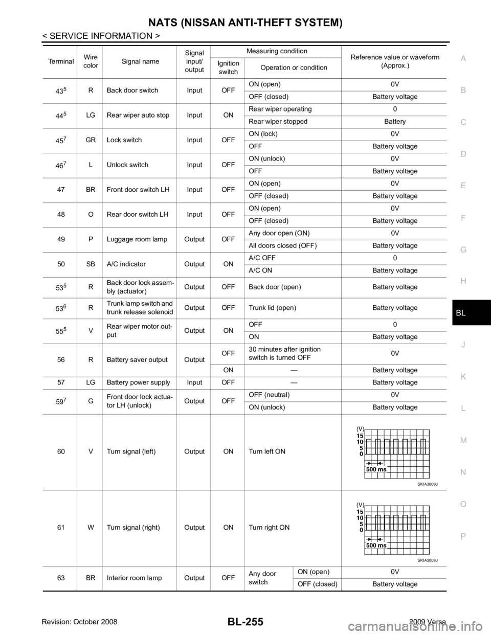
43
5
R Back door switch Input OFF ON (open) 0V
OFF (closed) Battery voltage
44 5
LG Rear wiper auto stop Input ON Rear wiper operating 0
Rear wiper stopped Battery
45 7
GR Lock switch Input OFF ON (lock) 0V
OFF Battery voltage
46 7
L Unlock switch Input OFF ON (unlock) 0V
OFF Battery voltage
47 BR Front door switch LH Input OFF ON (open) 0V
OFF (closed) Battery voltage
48 O Rear door switch LH Input OFF ON (open) 0V
OFF (closed) Battery voltage
49 P Luggage room lamp Output OFF Any door open (ON) 0V
All doors closed (OFF) Battery voltage
50 SB A/C indicator Output ON A/C OFF 0
A/C ON Battery voltage
53 5
RBack door lock assem-
bly (actuator) Output OFF Back door (open) Battery voltage
53 6
RTrunk lamp switch and
trunk release solenoid Output OFF Trunk lid (open) Battery voltage
55 5
VRear wiper motor out-
put Output ONOFF 0
ON Battery voltage
56 R Battery saver output Output OFF
30 minutes after ignition
switch is turned OFF 0V
ON — Battery voltage
57 LG Battery power supply Input OFF — Battery voltage
59 7
GFront door lock actua-
tor LH (unlock) Output OFFOFF (neutral) 0V
ON (unlock) Battery voltage
60 V Turn signal (left) Output ON Turn left ON
61 W Turn signal (right) Output ON Turn right ON
63 BR Interior room lamp Output OFF Any door
switch ON (open) 0V
OFF (closed) Battery voltage
Terminal
Wire
color Signal name Signal
input/
output Measuring condition
Reference value or waveform
(Approx.)
Ignition
switch Operation or condition SKIA3009J
SKIA3009J
Page 831 of 4331
BR
N
O P
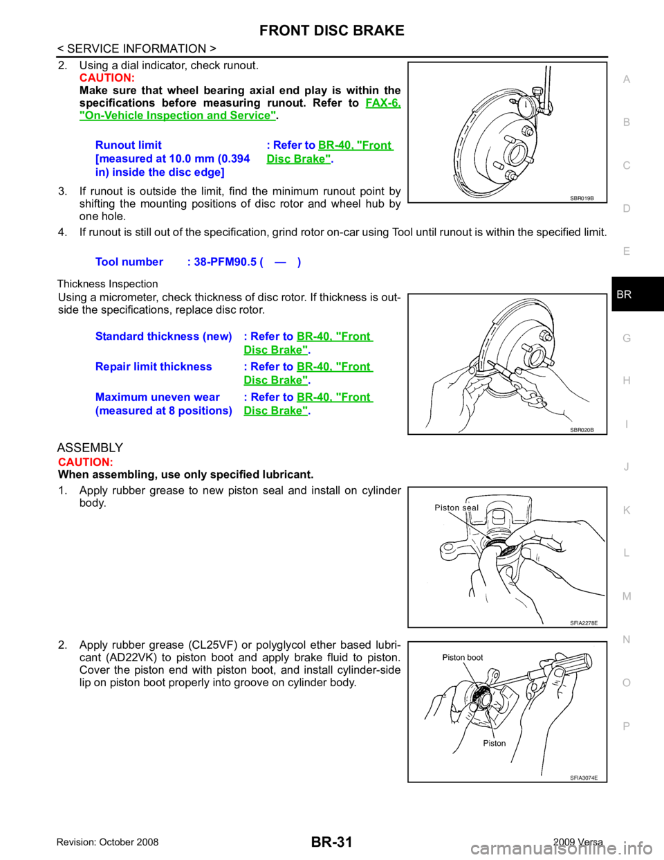
2. Using a dial indicator, check runout.
CAUTION:
Make sure that wheel bearing axi al end play is within the
specifications before measuring runout. Refer to FAX-6," On-Vehicle Inspection and Service " .
3. If runout is outside the limit, find the minimum runout point by shifting the mounting positions of disc rotor and wheel hub by
one hole.
4. If runout is still out of the specific ation, grind rotor on-car using Tool until runout is within the specified limit.
Thickness Inspection Using a micrometer, check thickness of disc rotor. If thickness is out-
side the specifications, replace disc rotor.
ASSEMBLY CAUTION:
When assembling, use only specified lubricant.
1. Apply rubber grease to new piston seal and install on cylinder body.
2. Apply rubber grease (CL25VF) or polyglycol ether based lubri- cant (AD22VK) to piston boot and apply brake fluid to piston.
Cover the piston end with piston boot, and install cylinder-side
lip on piston boot properly into groove on cylinder body. Runout limit
[measured at 10.0 mm (0.394
in) inside the disc edge] : Refer to
BR-40, " Front
Disc Brake " .
Tool number : 38-PFM90.5 ( — ) Front
Disc Brake " .
Repair limit thickness : Refer to BR-40, " Front
Disc Brake " .
Maximum uneven wear
(measured at 8 positions) : Refer to
BR-40, " Front
Disc Brake " .
Page 841 of 4331

BRC
N
O P
CONTENTS
BRAKE CONTROL SYSTEM
ABS
SERVICE INFORMATION .. ..........................
2
PRECAUTIONS .............................................. .....2
Precaution for Supplemental Restraint System
(SRS) "AIR BAG" and "SEAT BELT PRE-TEN-
SIONER" ............................................................. ......
2
Precaution for Brake System .............................. ......2
Precaution for Brake Cont rol .....................................3
Precaution for CAN System ................................ ......3
PREPARATION .............................................. .....4
Special Service Tool ........................................... ......4
Commercial Service Tool .................................... ......4
SYSTEM DESCRIPTION ................................ .....5
System Component ............................................. ......5
ABS Function ...................................................... ......5
EBD Function ...................................................... ......5
Fail-Safe Function ............................................... ......5
Hydraulic Circuit Diagram .........................................6
CAN COMMUNICATION ................................ .....7
System Description ............................................. ......7
TROUBLE DIAGNOSIS ................................. .....8
How to Perform Trouble Diagnosis for Quick and
Accurate Repair ........... .............................................
8
Component Parts and Harness Connector Loca-
tion ...................................................................... ....
11
Schematic ........................................................... ....12
Wiring Diagram - ABS - ... ........................................13 Basic Inspection ..................................................
....16
Warning Lamp and Indicator Timing .................... ....17
Control Unit Input/Output Signal Standard .......... ....17
CONSULT-III Function ( ABS) ..................................18
TROUBLE DIAGNOSIS FOR SELF-DIAG-
NOSTIC ITEMS ................................................. 24
Wheel Sensor System ......................................... ....24
ABS Control Unit Inspection ................................ ....25
Solenoid Valve System Inspection ...................... ....25
Actuator Motor, Motor Re lay, and Circuit Inspec-
tion ....................................................................... ....
26
ABS Control Unit Power and Ground Systems In-
spection ............................................................... ....
27
CAN Communication System Inspection ............. ....28
TROUBLE DIAGNOSES FOR SYMPTOMS ..... 29
ABS Works Frequently ........................................ ....29
Unexpected Pedal Action .................................... ....29
Long Stopping Distance ...................................... ....30
ABS Does Not Work ............................................ ....30
Pedal Vibration or ABS Op eration Noise .................30
WHEEL SENSORS ........................................... 32
Removal and Installation ..................................... ....32
SENSOR ROTOR .............................................. 34
Removal and Installation ..................................... ....34
ACTUATOR AND ELECTRIC UNIT (ASSEM-
BLY) .................................................................. 35
Removal and Installation ..................................... ....35
Page 945 of 4331

CVT
N
O P
CONTENTS
CVT
RE0F08A
SERVICE INFORMATION .. ..........................
9
INDEX FOR DTC ............................................ .....9
Alphabetical Index ............................................... ......9
DTC No. Index .................................................... ......9
PRECAUTIONS .............................................. ....11
Precaution for Supplemental Restraint System
(SRS) "AIR BAG" and "SEAT BELT PRE-TEN-
SIONER" ............................................................. ....
11
Precaution Necessary fo r Steering Wheel Rota-
tion After Battery Disconnect ............................... ....
11
Precaution for On Board Diagnosis (OBD) System
of CVT and Engine .............................................. ....
12
Service After Replacing TCM and Transaxle As-
sembly ................................................................. ....
12
Removal and Installation Procedure for CVT Unit
Connector ............................................................ ....
13
Precaution ........................................................... ....14
Service Notice or Precaution ............................... ....15
PREPARATION .............................................. ....16
Special Service Tool ........................................... ....16
Commercial Service Tool .................................... ....16
CVT FLUID ..................................................... ....17
Checking CVT Fluid ............................................ ....17
Changing CVT Fluid ............................................ ....18
CVT Fluid Cooler Cleanin g .....................................18
CVT SYSTEM ... .............................................. ....22
Cross-Sectional View - RE0F08A ....................... ....22
Control System .................................................... ....23
Hydraulic Control System ........................................24
TCM Function ...................................................... ....24
CAN Communication ........................................... ....25
Input/Output Signal of TCM ................................. ....26
Line Pressure and Secondary Pressure Control . ....26
Shift Control ........................................................ ....27
Lock-up and Select Control ................................. ....28 Control Valve .......................................................
....29
ON BOARD DIAGNOSTIC (OBD) SYSTEM .... 30
Introduction .......................................................... ....30
OBD-II Function for CVT System ........................ ....30
One or Two Trip Detection Logic of OBD-II ......... ....30
OBD-II Diagnostic Trouble Code (DTC) .............. ....30
Malfunction Indicator Lamp (MIL) ............................31
TROUBLE DIAGNOSIS .................................... 33
DTC Inspection Priority Chart .............................. ....33
Fail-Safe .............................................................. ....33
How to Perform Trouble Diagnosis for Quick and
Accurate Repair ................................................... ....
34
CVT Electrical Parts Location .............................. ....39
Circuit Diagram .................................................... ....40
Inspections before Trouble Diagnosis ................. ....40
Road Test ............................................................ ....44
Check before Engine Is Started ........................... ....45
Check at Idle ........................................................ ....45
Cruise Test .......................................................... ....47
Vehicle Speed When Shifting Gears ................... ....49
TCM Terminal and Refere nce Value .......................49
CONSULT-III Function (TRANSMISSION) .......... ....51
Diagnosis Procedure withou t CONSULT-III ............59
DTC U1000 CAN COMMUNICATION LINE ..... 60
Description ........................................................... ....60
On Board Diagnosis Logic ................................... ....60
Possible Cause .................................................... ....60
DTC Confirmation Procedure .............................. ....60
Wiring Diagram - CVT - CAN ............................... ....61
Diagnosis Procedure ........................................... ....62
DTC U1010 TRANSMISSION CONTROL
MODULE (CAN) ................................................ 63
Description ........................................................... ....63
On Board Diagnosis Logic ................................... ....63
Possible Cause .................................................... ....63
DTC Confirmation Procedure .............................. ....63
Diagnosis Procedure ........................................... ....63