2009 NISSAN TIIDA intake manifold
[x] Cancel search: intake manifoldPage 823 of 4331

BR
N
O P
VACUUM LINES
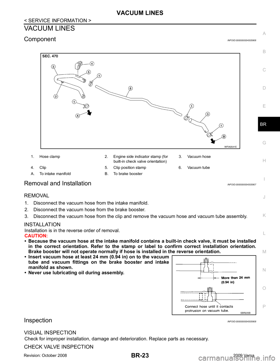
Component INFOID:0000000004305906
Removal and Installation INFOID:0000000004305907
REMOVAL 1. Disconnect the vacuum hose from the intake manifold.
2. Disconnect the vacuum hose from the brake booster.
3. Disconnect the vacuum hose from the clip and re move the vacuum hose and vacuum tube assembly.
INSTALLATION Installation is in the reverse order of removal.
CAUTION:
• Because the vacuum hose at the intake manifold contai ns a built-in check valve, it must be installed
in the correct orientation. Refer to the stamp or label to confirm correct installation orientation.
Brake booster will not operate normally if ho se is installed in the reverse orientation.
• Insert vacuum hose at least 24 mm (0.94 in) on to the vacuum tube and vacuum fittings on the brake booster and intake
manifold as shown.
• Never use lubricating oil during assembly.
Inspection INFOID:0000000004305908
VISUAL INSPECTION Check for improper installation, damage and deterioration. Replace parts as necessary.
CHECK VALVE INSPECTION 1. Hose clamp 2. Engine side indicator stamp (for
built-in check valve orientation)3. Vacuum hose
4. Clip 5. Clip position stamp 6. Vacuum tube
A. To intake manifold B. To brake booster SBR225B
Page 1399 of 4331

EC
NP
O
*3: ECM determines the start signal status by the signals of engine speed and battery voltage.
SYSTEM DESCRIPTION The amount of fuel injected from the fuel injector is determined by the ECM. The ECM controls the length of
time the valve remains open (injection pulse duration). T he amount of fuel injected is a program value in the
ECM memory. The program value is preset by engi ne operating conditions. These conditions are determined
by input signals (for engine speed and intake air) from t he crankshaft position sensor (POS), camshaft position
sensor (PHASE) and the mass air flow sensor.
VARIOUS FUEL INJECTION INCREASE/DECREASE COMPENSATION In addition, the amount of fuel injected is compens ated to improve engine performance under various operat-
ing conditions as listed below.
• During warm-up
• When starting the engine
• During acceleration
• Hot-engine operation
• When selector lever is changed from N to D (A/T models)
• High-load, high-speed operation
• During deceleration
• During high engine speed operation
MIXTURE RATIO FEEDBACK CONTROL (CLOSED LOOP CONTROL)
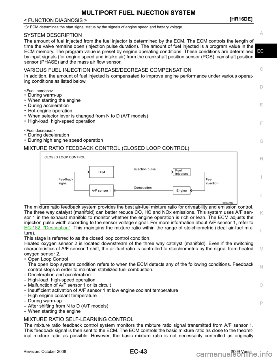
The mixture ratio feedback system prov ides the best air-fuel mixture ratio for driveability and emission control.
The three way catalyst (manifold) can better reduce CO, HC and NOx emissions. This system uses A/F sen-
sor 1 in the exhaust manifold to monitor whether the engine operation is rich or lean. The ECM adjusts the
injection pulse width according to the sensor voltage si gnal. For more information about A/F sensor 1, refer to
EC-182, " Description " . This maintains the mixture ratio within t
he range of stoichiometric (ideal air-fuel mix-
ture).
This stage is referred to as the closed loop control condition.
Heated oxygen sensor 2 is located downstream of the th ree way catalyst (manifold). Even if the switching
characteristics of A/F sensor 1 shift, the air-fuel rati o is controlled to stoichiometric by the signal from heated
oxygen sensor 2.
• Open Loop Control
The open loop system condition refers to when the EC M detects any of the following conditions. Feedback
control stops in order to maintain stabilized fuel combustion.
- Deceleration and acceleration
- High-load, high-speed operation
- Malfunction of A/F sensor 1 or its circuit
- Insufficient activation of A/F sensor 1 at low engine coolant temperature
- High engine coolant temperature
- During warm-up
- After shifting from N to D (A/T models)
- When starting the engine
MIXTURE RATIO SELF-LEARNING CONTROL The mixture ratio feedback control system monitors the mixture ratio signal transmitted from A/F sensor 1.
This feedback signal is then sent to the ECM. The ECM cont rols the basic mixture ratio as close to the theoret-
ical mixture ratio as possible. However, the basic mi xture ratio is not necessarily controlled as originally
Page 1431 of 4331

EC
NP
O
SYSTEM DESCRIPTION
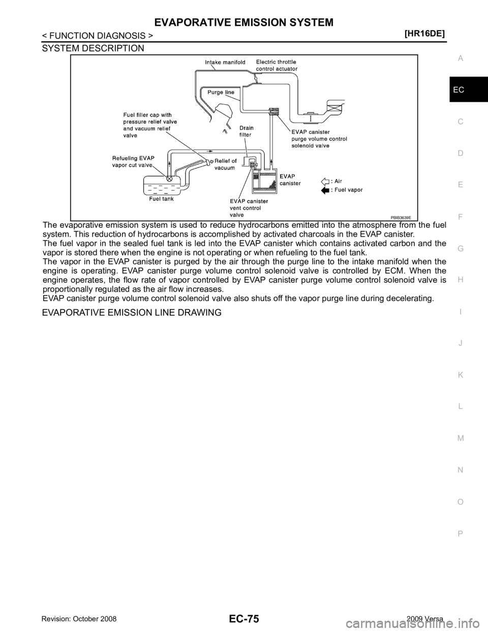
The evaporative emission system is used to reduce hydr ocarbons emitted into the atmosphere from the fuel
system. This reduction of hydrocarbons is accompli shed by activated charcoals in the EVAP canister.
The fuel vapor in the sealed fuel tank is led into t he EVAP canister which contains activated carbon and the
vapor is stored there when the engine is not oper ating or when refueling to the fuel tank.
The vapor in the EVAP canister is purged by the air through the purge line to the intake manifold when the
engine is operating. EVAP canister purge volume control solenoid valve is controlled by ECM. When the
engine operates, the flow rate of vapor controlled by EVAP canister purge volume control solenoid valve is
proportionally regulated as the air flow increases.
EVAP canister purge volume control solenoid valve al so shuts off the vapor purge line during decelerating.
EVAPORATIVE EMISSION LINE DRAWING
Page 1444 of 4331
![NISSAN TIIDA 2009 Service Repair Manual EC-88< FUNCTION DIAGNOSIS >
[HR16DE]
INTAKE VALVE TIMING CONTROL
1. Air fuel ratio (A/F) sensor 1 2. Three way catalyst (Manifold) 3. Heated oxygen sensor 2
4. Three way catalyst (Under flloor) 5. Muf NISSAN TIIDA 2009 Service Repair Manual EC-88< FUNCTION DIAGNOSIS >
[HR16DE]
INTAKE VALVE TIMING CONTROL
1. Air fuel ratio (A/F) sensor 1 2. Three way catalyst (Manifold) 3. Heated oxygen sensor 2
4. Three way catalyst (Under flloor) 5. Muf](/manual-img/5/57398/w960_57398-1443.png)
EC-88< FUNCTION DIAGNOSIS >
[HR16DE]
INTAKE VALVE TIMING CONTROL
1. Air fuel ratio (A/F) sensor 1 2. Three way catalyst (Manifold) 3. Heated oxygen sensor 2
4. Three way catalyst (Under flloor) 5. Muffler
Vehicle front
1. Exhaust manifold 2. Air fuel ratio (A/F) sensor 1 3. Heated oxygen sensor 2
4. Heated oxygen sensor 2 harness connector
Vehicle front JMBIA2192ZZ
PBIB2943E
Page 1514 of 4331
![NISSAN TIIDA 2009 Service Repair Manual EC-158< COMPONENT DIAGNOSIS >
[HR16DE]
P0102, P0103 MAF SENSOR
P0102 >> GO TO 2.
P0103 >> GO TO 3. 2.
CHECK INTAKE SYSTEM
Check the following for connection.
• Air duct
• Vacuum hoses
• Intake a NISSAN TIIDA 2009 Service Repair Manual EC-158< COMPONENT DIAGNOSIS >
[HR16DE]
P0102, P0103 MAF SENSOR
P0102 >> GO TO 2.
P0103 >> GO TO 3. 2.
CHECK INTAKE SYSTEM
Check the following for connection.
• Air duct
• Vacuum hoses
• Intake a](/manual-img/5/57398/w960_57398-1513.png)
EC-158< COMPONENT DIAGNOSIS >
[HR16DE]
P0102, P0103 MAF SENSOR
P0102 >> GO TO 2.
P0103 >> GO TO 3. 2.
CHECK INTAKE SYSTEM
Check the following for connection.
• Air duct
• Vacuum hoses
• Intake air passage between air duct to intake manifold
Is the inspection result normal? YES >> GO TO 3.
NO >> Reconnect the parts. 3.
CHECK GROUND CONNECTION
1. Turn ignition switch OFF.
2. Check ground connections E15, E24. Refer to EC-125, " Ground Inspection " .
Is the inspection result normal? YES >> GO TO 4.
NO >> Repair or replace ground connection. 4.
CHECK MAF SENSOR POWER SUPPLY CIRCUIT
1. Disconnect mass air flow (MAF) sensor harness connector.
2. Turn ignition switch ON.
3. Check the voltage between MAF sensor harness connector and ground.
Is the inspection result normal? YES >> GO TO 6.
NO >> GO TO 5. 5.
DETECT MALFUNCTIONING PART
Check the following.
• Harness connectors E8, F8
• Harness for open or short between mass air flow sensor and ECM
• Harness for open or short between mass air flow sensor and IPDM E/R
>> Repair open circuit or short to ground or short to power in harness or connectors. 6.
CHECK MAF SENSOR GROUND CIRCUIT FOR OPEN AND SHORT
1. Turn ignition switch OFF.
2. Disconnect ECM harness connector.
3. Check the continuity between MAF sens or harness connector and ECM harness connector.
4. Also check harness for short to ground and short to power.
Is the inspection result normal? YES >> GO TO 7.
NO >> Repair open circuit or short to ground or short to power in harness or connectors. 7.
CHECK MAF SENSOR INPUT SIGNAL CIRCUIT FOR OPEN AND SHORT
1. Check the continuity between MAF sens or harness connector and ECM harness connector.
MAF sensor
Ground Voltage
Connector Terminal
F31 2 Ground Battery voltage PBIB1168E
MAF sensor ECM
Continuity
Connector Terminal Connector Terminal
F31 3 F11 52 Existed
Page 1577 of 4331
![NISSAN TIIDA 2009 Service Repair Manual P0139 HO2S2
EC-221
< COMPONENT DIAGNOSIS >
[HR16DE] C
D E
F
G H
I
J
K L
M A EC
NP
O
P0139 HO2S2
Description INFOID:0000000004780130
The heated oxygen sensor 2, after three way catalyst (manif NISSAN TIIDA 2009 Service Repair Manual P0139 HO2S2
EC-221
< COMPONENT DIAGNOSIS >
[HR16DE] C
D E
F
G H
I
J
K L
M A EC
NP
O
P0139 HO2S2
Description INFOID:0000000004780130
The heated oxygen sensor 2, after three way catalyst (manif](/manual-img/5/57398/w960_57398-1576.png)
P0139 HO2S2
EC-221
< COMPONENT DIAGNOSIS >
[HR16DE] C
D E
F
G H
I
J
K L
M A EC
NP
O
P0139 HO2S2
Description INFOID:0000000004780130
The heated oxygen sensor 2, after three way catalyst (manifold),
monitors the oxygen level in the exhaust gas on each bank.
Even if switching characteristics of the air fuel ratio (A/F) sensor 1
are shifted, the air-fuel ratio is controlled to stoichiometric, by the sig-
nal from the heated oxygen sensor 2.
This sensor is made of ceramic zirconia. The zirconia generates volt-
age from approximately 1 V in richer conditions to 0 V in leaner con-
ditions.
Under normal conditions the heated oxygen sensor 2 is not used for
engine control operation.
DTC Logic INFOID:0000000004780131
DTC DETECTION LOGIC The heated oxygen sensor 2 has a much longer switching time
between rich and lean than the air fuel ratio (A/F) sensor 1. The oxy-
gen storage capacity of the three way catalyst (manifold) causes the
longer switching time. To judge the malfunctions of heated oxygen
sensor 2, ECM monitors whether the switching response of the sen-
sor's voltage is faster than specified during the various driving condi-
tion such as fuel-cut.
DTC CONFIRMATION PROCEDURE 1.
INSPECTION START
Do you have CONSULT-III?
Do you have CONSULT-III? YES >> GO TO 2.
NO >> GO TO 5. 2.
PRECONDITIONING
If DTC Confirmation Procedure has been previously conduc ted, always turn ignition switch OFF and wait at
least 10 seconds before conducting the next test.
>> GO TO 3. 3.
PERFORM DTC CONFIRMATION PROCEDURE
With CONSULT-III
1. Turn ignition switch ON and select “DATA MONITOR” mode with CONSULT-III.
2. Start engine and warm it up to normal operating temperature. SEF327R
SEF302U
DTC No. Trouble diagnosis name DTC detecting condition Possible cause
P0139 Heated oxygen sensor 2
circuit slow response It takes more time for the sensor to respond
between rich and lean than the specified
time. • Harness or connectors
(The sensor circuit is open or shorted)
• Heated oxygen sensor 2
• Fuel pressure
• Fuel injector
• Intake air leaks
Page 1588 of 4331
![NISSAN TIIDA 2009 Service Repair Manual EC-232< COMPONENT DIAGNOSIS >
[HR16DE]
P0171 FUEL INJECTION SYSTEM FUNCTION
2. Listen for an exhaust gas leak before three way catalyst (manifold).
Is exhaust gas leak detected? YES >> Repair or repla NISSAN TIIDA 2009 Service Repair Manual EC-232< COMPONENT DIAGNOSIS >
[HR16DE]
P0171 FUEL INJECTION SYSTEM FUNCTION
2. Listen for an exhaust gas leak before three way catalyst (manifold).
Is exhaust gas leak detected? YES >> Repair or repla](/manual-img/5/57398/w960_57398-1587.png)
EC-232< COMPONENT DIAGNOSIS >
[HR16DE]
P0171 FUEL INJECTION SYSTEM FUNCTION
2. Listen for an exhaust gas leak before three way catalyst (manifold).
Is exhaust gas leak detected? YES >> Repair or replace.
NO >> GO TO 2. 2.
CHECK FOR INTAKE AIR LEAK
1. Listen for an intake air leak after the mass air flow sensor.
2. Check PCV hose connection.
Intake air leak detected? YES >> Repair or replace.
NO >> GO TO 3. 3.
CHECK A/F SENSOR 1 INPUT SIGNAL CIRCUIT
1. Turn ignition switch OFF.
2. Disconnect corresponding A/F sensor 1 harness connector.
3. Disconnect ECM harness connector.
4. Check the continuity between A/F sensor 1 harness connector and ECM harness connector.
5. Check the continuity between A/F sensor 1 harness connector and ground, or ECM harness connector
and ground.
6. Also check harness for short to power.
Is the inspection result normal? YES >> GO TO 4.
NO >> Repair open circuit or short to ground or short to power in harness or connectors. 4.
CHECK FUEL PRESSURE
1. Check fuel pressure. Refer to EC-498, " Inspection " .
Is the inspection result normal? YES >> GO TO 6. PBIB1216E
A/F sensor 1 ECM
Continuity
Connector Terminal Connector Terminal
F12 1
F11 49
Existed
2 53
A/F sensor 1 Ground Continuity
Connector Terminal
F12 1
Ground Not existed
2
ECM Ground Continuity
Connector Terminal
F11 49
Ground Not existed
53
Page 1594 of 4331
![NISSAN TIIDA 2009 Service Repair Manual EC-238< COMPONENT DIAGNOSIS >
[HR16DE]
P0172 FUEL INJECTION SYSTEM FUNCTION
2. Listen for an exhaust gas leak before three way catalyst (manifold).
Is exhaust gas leak detected? YES >> Repair or repla NISSAN TIIDA 2009 Service Repair Manual EC-238< COMPONENT DIAGNOSIS >
[HR16DE]
P0172 FUEL INJECTION SYSTEM FUNCTION
2. Listen for an exhaust gas leak before three way catalyst (manifold).
Is exhaust gas leak detected? YES >> Repair or repla](/manual-img/5/57398/w960_57398-1593.png)
EC-238< COMPONENT DIAGNOSIS >
[HR16DE]
P0172 FUEL INJECTION SYSTEM FUNCTION
2. Listen for an exhaust gas leak before three way catalyst (manifold).
Is exhaust gas leak detected? YES >> Repair or replace.
NO >> GO TO 2. 2.
CHECK FOR INTAKE AIR LEAK
Listen for an intake air leak after the mass air flow sensor.
Is intake air leak detected? YES >> Repair or replace.
NO >> GO TO 3. 3.
CHECK A/F SENSOR 1 INPUT SIGNAL CIRCUIT
1. Turn ignition switch OFF.
2. Disconnect corresponding A/F sensor 1 harness connector.
3. Disconnect ECM harness connector.
4. Check the continuity between A/F sensor 1 harness connector and ECM harness connector.
5. Check the continuity between A/F sensor 1 harness connector and ground, or ECM harness connector
and ground.
6. Also check harness for short to power.
Is the inspection result normal? YES >> GO TO 4.
NO >> Repair open circuit or short to ground or short to power in harness or connectors. 4.
CHECK FUEL PRESSURE
1. Check fuel pressure. Refer to EC-498, " Inspection " .
Is the inspection result normal? YES >> GO TO 6.
NO >> GO TO 5. PBIB1216E
A/F sensor 1 ECM
Continuity
Connector Terminal Connector Terminal
F12 1
F11 49
Existed
2 53
A/F sensor 1 Ground Continuity
Connector Terminal
F12 1
Ground Not existed
2
ECM Ground Continuity
Connector Terminal
F11 49
Ground Not existed
53