2009 NISSAN TIIDA compression ratio
[x] Cancel search: compression ratioPage 1465 of 4331

EC
NP
O
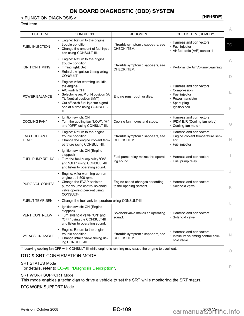
Test Item
*: Leaving cooling fan OFF with CONSULT-III while engine is running may cause the engine to overheat.
DTC & SRT CONFIRMATION MODE
SRT STATUS Mode For details, refer to EC-90, " Diagnosis Description " .
SRT WORK SUPPORT Mode This mode enables a technician to drive a vehicle to set the SRT while monitoring the SRT status.
DTC WORK SUPPORT Mode TEST ITEM CONDITION JUDGMENT CHECK ITEM (REMEDY)
FUEL INJECTION • Engine: Return to the original
trouble condition
• Change the amount of fuel injec- tion using CONSULT-III. If trouble symptom disappears, see
CHECK ITEM. • Harness and connectors
• Fuel injector
• Air fuel ratio (A/F) sensor 1
IGNITION TIMING • Engine: Return to the original
trouble condition
• Timing light: Set
• Retard the ignition timing using
CONSULT-III. If trouble symptom disappears, see
CHECK ITEM. • Perform Idle Air Volume Learning.
POWER BALANCE • Engine: After warming up, idle
the engine.
• A/C switch OFF
• Selector lever: P or N position (A/ T), Neutral position (M/T)
• Cut off each fuel injector signal
one at a time using CONSULT-
III. Engine runs rough or dies.
• Harness and connectors
• Compression
• Fuel injector
• Power transistor
• Spark plug
• Ignition coil
COOLING FAN* • Ignition switch: ON
• Turn the cooling fan “LOW”, “HI”
and “OFF” using CONSULT-III. Cooling fan moves and stops.
• Harness and connectors
• IPDM E/R (Cooling fan relay)
• Cooling fan motor
ENG COOLANT
TEMP • Engine: Return to the original
trouble condition
• Change the engine coolant tem-
perature using CONSULT-III. If trouble symptom disappears, see
CHECK ITEM. • Harness and connectors
• Engine coolant temperature sen- sor
• Fuel injector
FUEL PUMP RELAY • Ignition switch: ON (Engine
stopped)
• Turn the fuel pump relay “ON”
and “OFF” using CONSULT-III
and listen to operating sound. Fuel pump relay makes the operat-
ing sound. • Harness and connectors
• Fuel pump relay
PURG VOL CONT/V • Engine: After warming up, run
engine at 1,500 rpm.
• Change the EVAP canister purge volume control solenoid
valve opening percent using
CONSULT-III. Engine speed changes according
to the opening percent. • Harness and connectors
• Solenoid valve
FUEL/T TEMP SEN • Change the fuel tank temperature using CONSULT-III.
VENT CONTROL/V • Ignition switch: ON (Engine
stopped)
• Turn solenoid valve “ON” and “OFF” using th e CONSULT-III
and listen to operating sound. Solenoid valve makes an operating
sound. • Harness and connectors
• Solenoid valve
V/T ASSIGN ANGLE • Engine: Return to the original
trouble condition
• Change intake valve timing us-
ing CONSULT-III. If trouble symptom disappears, see
CHECK ITEM. • Harness and connectors
• Intake valve timing control sole- noid valve
Page 1609 of 4331

EC
NP
O
P0300, P0301, P0302, P0303, P0304 MISFIRE
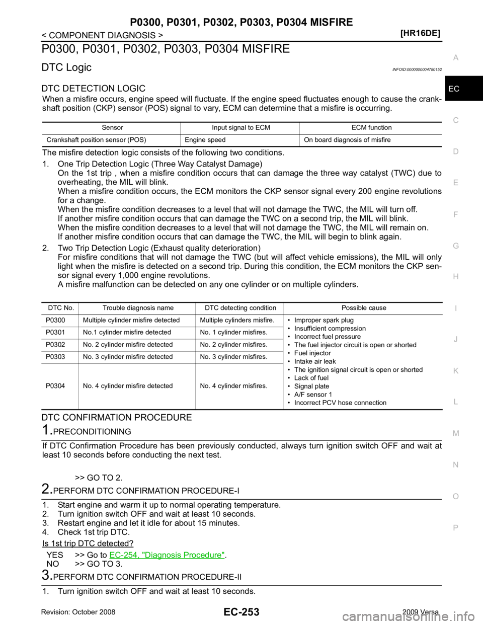
DTC Logic INFOID:0000000004780152
DTC DETECTION LOGIC When a misfire occurs, engine speed will fluctuate. If the engine speed fluctuates enough to cause the crank-
shaft position (CKP) sensor (POS) signal to vary , ECM can determine that a misfire is occurring.
The misfire detection logic consists of the following two conditions.
1. One Trip Detection Logic (Three Way Catalyst Damage) On the 1st trip , when a misfire condition occurs that can damage the three way catalyst (TWC) due to
overheating, the MIL will blink.
When a misfire condition occurs, the ECM monitors the CKP sensor signal every 200 engine revolutions
for a change.
When the misfire condition decreases to a level t hat will not damage the TWC, the MIL will turn off.
If another misfire condition occurs that can damage the TWC on a second trip, the MIL will blink.
When the misfire condition decreases to a level t hat will not damage the TWC, the MIL will remain on.
If another misfire condition occurs that can damage the TWC, the MIL will begin to blink again.
2. Two Trip Detection Logic (Exhaust quality deterioration) For misfire conditions that will not damage the TWC (but will affect vehicle emissions), the MIL will only
light when the misfire is detected on a second trip. Du ring this condition, the ECM monitors the CKP sen-
sor signal every 1,000 engine revolutions.
A misfire malfunction can be detected on any one cylinder or on multiple cylinders.
DTC CONFIRMATION PROCEDURE YES >> Go to
EC-254, " Diagnosis Procedure " .
NO >> GO TO 3. DTC No. Trouble diagnosis name DTC detecting condition Possible cause
P0300 Multiple cylinder misfire detected Multiple cylinders misfire. • Improper spark plug • Insufficient compression
• Incorrect fuel pressure
• The fuel injector circuit is open or shorted
• Fuel injector
• Intake air leak
• The ignition signal circuit is open or shorted
• Lack of fuel
• Signal plate
• A/F sensor 1
• Incorrect PCV hose connection
P0301 No.1 cylinder misfire detected No. 1 cylinder misfires.
P0302 No. 2 cylinder misfire detected No. 2 cylinder misfires.
P0303 No. 3 cylinder misfire detected No. 3 cylinder misfires.
P0304 No. 4 cylinder misfire detected No. 4 cylinder misfires.
Page 1967 of 4331
![NISSAN TIIDA 2009 Service Repair Manual EC
NP
O
NOTE:
Any monitored item that does not match the vehicle being diagnosed is deleted from the display automatically.
ACTIVE TEST MODE
Test Item AT OD CANCEL
[ON/OFF] • Indicates [ON/OFF] cond NISSAN TIIDA 2009 Service Repair Manual EC
NP
O
NOTE:
Any monitored item that does not match the vehicle being diagnosed is deleted from the display automatically.
ACTIVE TEST MODE
Test Item AT OD CANCEL
[ON/OFF] • Indicates [ON/OFF] cond](/manual-img/5/57398/w960_57398-1966.png)
EC
NP
O
NOTE:
Any monitored item that does not match the vehicle being diagnosed is deleted from the display automatically.
ACTIVE TEST MODE
Test Item AT OD CANCEL
[ON/OFF] • Indicates [ON/OFF] condition of A/T O/D cancel signal sent
from the TCM. • For M/T models always “OFF” is displayed
CRUISE LAMP
[ON/OFF] • Indicates [ON/OFF]
condition of CRUISE lamp determined
by the ECM according to the input signals.
SET LAMP
[ON/OFF] • Indicates [ON/OFF] condition of SET lamp determined by the
ECM according to the input signals.
A/F ADJ-B1 • Indicates the correction factor stored in ECM. The factor is
calculated from the difference between the target air/fuel ratio
stored in ECM and the air/fuel ratio calculated from air fuel ra-
tio (A/F) sensor 1 signal.
Monitored item [Unit] Description Remarks TEST ITEM CONDITION JUDGEMENT CHECK ITEM (REMEDY)
FUEL INJEC-
TION • Engine: Return to the original
trouble condition
• Change the amount of fuel injec- tion using CONSULT-III. If trouble symptom disappears, see
CHECK ITEM. • Harness and connectors
• Fuel injector
• Air fuel ratio (A/F) sensor 1
IGNITION TIM-
ING • Engine: Return to the original
trouble condition
• Timing light: Set
• Retard the ignition timing using
CONSULT-III. If trouble symptom disappears, see
CHECK ITEM. • Perform Idle Air Volume Learning.
POWER BAL-
ANCE • Engine: After warming up, idle the
engine.
• A/C switch OFF
• Shift lever: P or N (A/T, CVT), Neutral (M/T)
• Cut off each fuel injector signal
one at a time using CONSULT-III. Engine runs rough or dies.
• Harness and connectors
• Compression
• Fuel injector
• Power transistor
• Spark plug
• Ignition coil
COOLING FAN* • Ignition switch: ON
• Turn the cooling fan “LOW”, “HI” and “OFF” with CONSULT-III. Cooling fan moves and stops. • Harness and connectors
• Cooling fan relay
• Cooling fan motor
ENG COOLANT
TEMP • Engine: Return to the original
trouble condition
• Change the engine coolant tem- perature using CONSULT-III. If trouble symptom disappears, see
CHECK ITEM. • Harness and connectors
• Engine coolant temperature sen-
sor
• Fuel injector
FUEL PUMP RE-
LAY • Ignition switch: ON
(Engine stopped)
• Turn the fuel pump relay ON and OFF using CONSULT-III and lis-
ten to operating sound. Fuel pump relay makes the operat-
ing sound. • Harness and connectors
• Fuel pump relay
PURG VOL
CONT/V • Engine: After warming up, run en-
gine at 1,500 rpm.
• Change the EVAP canister purge volume control solenoid valve
opening percent using CON-
SULT-III. Engine speed changes according to
the opening percent. • Harness and connectors
• EVAP canister purge volume con- trol solenoid valve
FUEL/T TEMP
SEN • Change the fuel tank temperature using CONSULT-III.
Page 2121 of 4331

EC
NP
O
DTC P0300 - P0304 MULTIPLE CYLINDER
MISFIRE, NO. 1 - 4 CYLINDER
MISFIRE
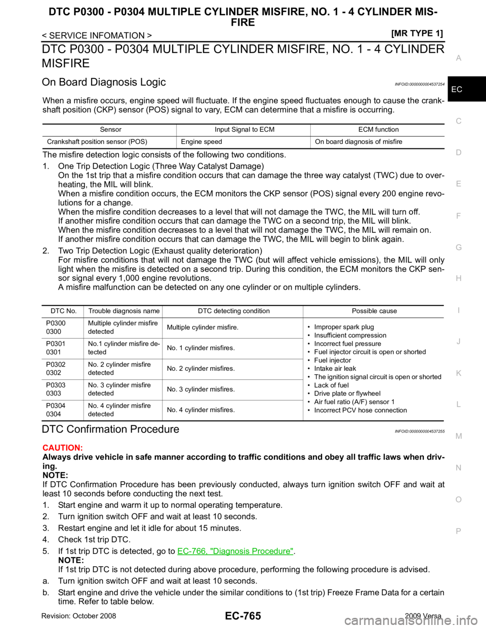
On Board Diagnosis Logic INFOID:0000000004537254
When a misfire occurs, engine speed will fluctuate. If the engine speed fluctuates enough to cause the crank-
shaft position (CKP) sensor (POS) signal to vary , ECM can determine that a misfire is occurring.
The misfire detection logic consists of the following two conditions.
1. One Trip Detection Logic (Three Way Catalyst Damage) On the 1st trip that a misfire condition occurs that can damage the three way catalyst (TWC) due to over-
heating, the MIL will blink.
When a misfire condition occurs, the ECM monitors the CKP sensor (POS) signal every 200 engine revo-
lutions for a change.
When the misfire condition decreases to a level t hat will not damage the TWC, the MIL will turn off.
If another misfire condition occurs that can damage the TWC on a second trip, the MIL will blink.
When the misfire condition decreases to a level t hat will not damage the TWC, the MIL will remain on.
If another misfire condition occurs that can damage the TWC, the MIL will begin to blink again.
2. Two Trip Detection Logic (Exhaust quality deterioration) For misfire conditions that will not damage the TWC (but will affect vehicle emissions), the MIL will only
light when the misfire is detected on a second trip. Du ring this condition, the ECM monitors the CKP sen-
sor signal every 1,000 engine revolutions.
A misfire malfunction can be detected on any one cylinder or on multiple cylinders.
DTC Confirmation Procedure INFOID:0000000004537255
CAUTION:
Always drive vehicle in safe manner according to traf fic conditions and obey all traffic laws when driv-
ing.
NOTE:
If DTC Confirmation Procedure has been previously conduc ted, always turn ignition switch OFF and wait at
least 10 seconds before conducting the next test.
1. Start engine and warm it up to normal operating temperature.
2. Turn ignition switch OFF and wait at least 10 seconds.
3. Restart engine and let it idle for about 15 minutes.
4. Check 1st trip DTC.
5. If 1st trip DTC is detected, go to EC-766, " Diagnosis Procedure " .
NOTE:
If 1st trip DTC is not detected during above proc edure, performing the following procedure is advised.
a. Turn ignition switch OFF and wait at least 10 seconds.
b. Start engine and drive the vehicle under the similar conditi ons to (1st trip) Freeze Frame Data for a certain
time. Refer to table below. Sensor Input Signal to ECM ECM function
Crankshaft position sensor (POS) Engine speed On board diagnosis of misfire DTC No. Trouble diagnosis name DTC detecting condition Possible cause
P0300
0300 Multiple cylinder misfire
detected Multiple cylinder misfire.
• Improper spark plug
• Insufficient compression
• Incorrect fuel pressure
• Fuel injector circuit is open or shorted
• Fuel injector
• Intake air leak
• The ignition signal circuit is open or shorted
• Lack of fuel
• Drive plate or flywheel
• Air fuel ratio (A/F) sensor 1
• Incorrect PCV hose connection
P0301
0301 No.1 cylinder misfire de-
tected No. 1 cylinder misfires.
P0302
0302 No. 2 cylinder misfire
detected No. 2 cylinder misfires.
P0303
0303 No. 3 cylinder misfire
detected No. 3 cylinder misfires.
P0304
0304 No. 4 cylinder misfire
detected No. 4 cylinder misfires.
Page 2479 of 4331
![NISSAN TIIDA 2009 Service Repair Manual EC
NP
O
NOTE:
Any monitored item that does not match the vehicle being diagnosed is deleted from the display automatically.
ACTIVE TEST MODE
Test Item AT OD CANCEL
[ON/OFF] • Indicates [ON/OFF] cond NISSAN TIIDA 2009 Service Repair Manual EC
NP
O
NOTE:
Any monitored item that does not match the vehicle being diagnosed is deleted from the display automatically.
ACTIVE TEST MODE
Test Item AT OD CANCEL
[ON/OFF] • Indicates [ON/OFF] cond](/manual-img/5/57398/w960_57398-2478.png)
EC
NP
O
NOTE:
Any monitored item that does not match the vehicle being diagnosed is deleted from the display automatically.
ACTIVE TEST MODE
Test Item AT OD CANCEL
[ON/OFF] • Indicates [ON/OFF] condition of A/T O/D cancel signal sent
from the TCM. • For M/T models always “OFF” is displayed
CRUISE LAMP
[ON/OFF] • Indicates [ON/OFF]
condition of CRUISE lamp determined
by the ECM according to the input signals.
SET LAMP
[ON/OFF] • Indicates [ON/OFF] condition of SET lamp determined by the
ECM according to the input signals.
A/F ADJ-B1 • Indicates the correction factor stored in ECM. The factor is
calculated from the difference between the target air/fuel ratio
stored in ECM and the air/fuel ratio calculated from air fuel ra-
tio (A/F) sensor 1 signal.
Monitored item [Unit] Description Remarks TEST ITEM CONDITION JUDGMENT CHECK ITEM (REMEDY)
FUEL INJEC-
TION • Engine: Return to the original
trouble condition
• Change the amount of fuel injec- tion using CONSULT-III. If trouble symptom disappears, see
CHECK ITEM. • Harness and connectors
• Fuel injector
• Air fuel ratio (A/F) sensor 1
IGNITION TIM-
ING • Engine: Return to the original
trouble condition
• Timing light: Set
• Retard the ignition timing using
CONSULT-III. If trouble symptom disappears, see
CHECK ITEM. • Perform Idle Air Volume Learning.
POWER BAL-
ANCE • Engine: After warming up, idle the
engine.
• A/C switch OFF
• Shift lever: P or N (A/T, CVT), Neutral (M/T)
• Cut off each fuel injector signal
one at a time using CONSULT-III. Engine runs rough or dies.
• Harness and connectors
• Compression
• Fuel injector
• Power transistor
• Spark plug
• Ignition coil
COOLING FAN* • Ignition switch: ON
• Turn the cooling fan “LOW”, “HI” and “OFF” with CONSULT-III. Cooling fan moves and stops. • Harness and connectors
• Cooling fan relay
• Cooling fan motor
ENG COOLANT
TEMP • Engine: Return to the original
trouble condition
• Change the engine coolant tem- perature using CONSULT-III. If trouble symptom disappears, see
CHECK ITEM. • Harness and connectors
• Engine coolant temperature sen-
sor
• Fuel injector
FUEL PUMP RE-
LAY • Ignition switch: ON
(Engine stopped)
• Turn the fuel pump relay ON and OFF using CONSULT-III and lis-
ten to operating sound. Fuel pump relay makes the operat-
ing sound. • Harness and connectors
• Fuel pump relay
PURG VOL
CONT/V • Engine: After warming up, run en-
gine at 1,500 rpm.
• Change the EVAP canister purge volume control solenoid valve
opening percent using CON-
SULT-III. Engine speed changes according to
the opening percent. • Harness and connectors
• EVAP canister purge volume con- trol solenoid valve
FUEL/T TEMP
SEN • Change the fuel tank temperature using CONSULT-III.
Page 2639 of 4331

EC
NP
O
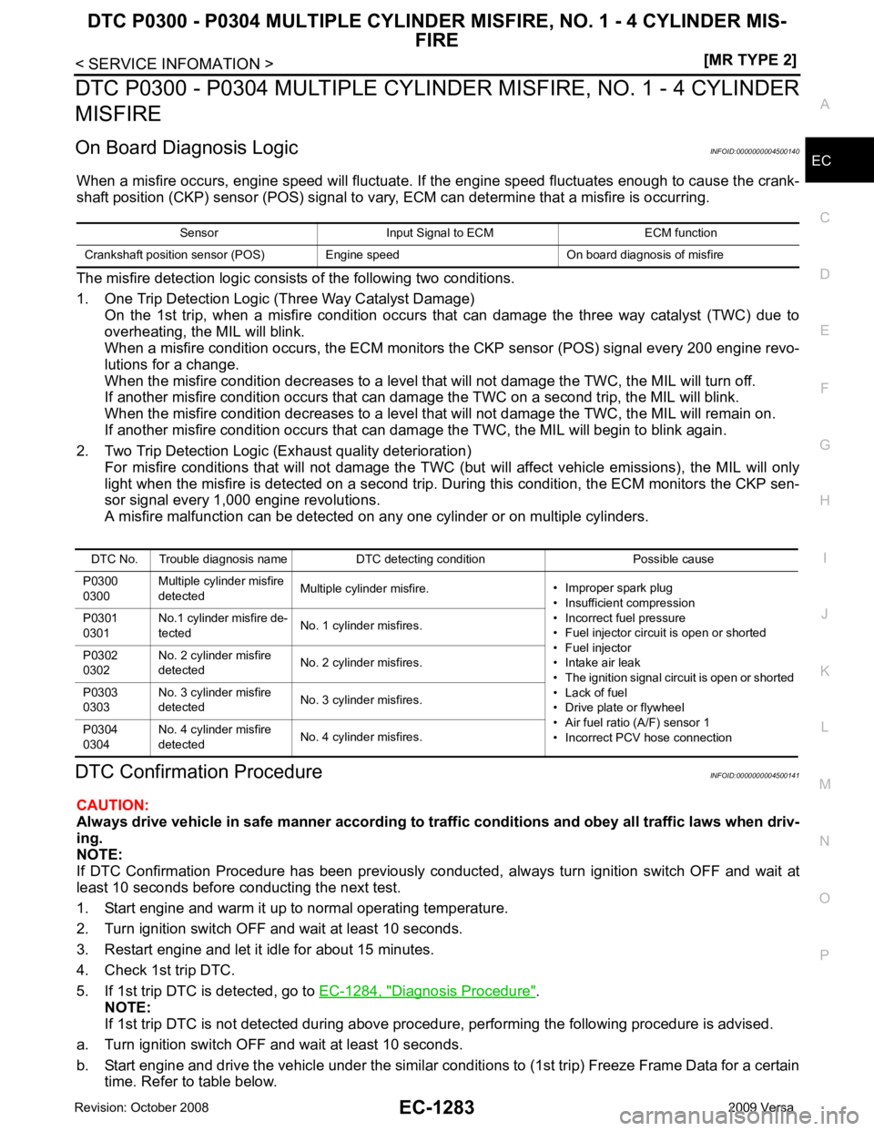
DTC P0300 - P0304 MULTIPLE CYLINDER
MISFIRE, NO. 1 - 4 CYLINDER
MISFIRE
On Board Diagnosis Logic INFOID:0000000004500140
When a misfire occurs, engine speed will fluctuate. If the engine speed fluctuates enough to cause the crank-
shaft position (CKP) sensor (POS) signal to vary , ECM can determine that a misfire is occurring.
The misfire detection logic consists of the following two conditions.
1. One Trip Detection Logic (Three Way Catalyst Damage) On the 1st trip, when a misfire condition occurs that can damage the three way catalyst (TWC) due to
overheating, the MIL will blink.
When a misfire condition occurs, the ECM monitors the CKP sensor (POS) signal every 200 engine revo-
lutions for a change.
When the misfire condition decreases to a level t hat will not damage the TWC, the MIL will turn off.
If another misfire condition occurs that can damage the TWC on a second trip, the MIL will blink.
When the misfire condition decreases to a level t hat will not damage the TWC, the MIL will remain on.
If another misfire condition occurs that can damage the TWC, the MIL will begin to blink again.
2. Two Trip Detection Logic (Exhaust quality deterioration) For misfire conditions that will not damage the TWC (but will affect vehicle emissions), the MIL will only
light when the misfire is detected on a second trip. Du ring this condition, the ECM monitors the CKP sen-
sor signal every 1,000 engine revolutions.
A misfire malfunction can be detected on any one cylinder or on multiple cylinders.
DTC Confirmation Procedure INFOID:0000000004500141
CAUTION:
Always drive vehicle in safe manner according to traf fic conditions and obey all traffic laws when driv-
ing.
NOTE:
If DTC Confirmation Procedure has been previously conduc ted, always turn ignition switch OFF and wait at
least 10 seconds before conducting the next test.
1. Start engine and warm it up to normal operating temperature.
2. Turn ignition switch OFF and wait at least 10 seconds.
3. Restart engine and let it idle for about 15 minutes.
4. Check 1st trip DTC.
5. If 1st trip DTC is detected, go to EC-1284, " Diagnosis Procedure " .
NOTE:
If 1st trip DTC is not detected during above proc edure, performing the following procedure is advised.
a. Turn ignition switch OFF and wait at least 10 seconds.
b. Start engine and drive the vehicle under the similar conditi ons to (1st trip) Freeze Frame Data for a certain
time. Refer to table below. Sensor Input Signal to ECM ECM function
Crankshaft position sensor (POS) Engine speed On board diagnosis of misfire DTC No. Trouble diagnosis name DTC detecting condition Possible cause
P0300
0300 Multiple cylinder misfire
detected Multiple cylinder misfire.
• Improper spark plug
• Insufficient compression
• Incorrect fuel pressure
• Fuel injector circuit is open or shorted
• Fuel injector
• Intake air leak
• The ignition signal circuit is open or shorted
• Lack of fuel
• Drive plate or flywheel
• Air fuel ratio (A/F) sensor 1
• Incorrect PCV hose connection
P0301
0301 No.1 cylinder misfire de-
tected No. 1 cylinder misfires.
P0302
0302 No. 2 cylinder misfire
detected No. 2 cylinder misfires.
P0303
0303 No. 3 cylinder misfire
detected No. 3 cylinder misfires.
P0304
0304 No. 4 cylinder misfire
detected No. 4 cylinder misfires.
Page 2948 of 4331

EM
N
O P
CONTENTS
ENGINE MECHANICAL
HR16DE
PRECAUTION ....... ........................................
4
PRECAUTIONS .............................................. .....4
Precaution for Supplemental Restraint System
(SRS) "AIR BAG" and "SEAT BELT PRE-TEN-
SIONER" ............................................................. ......
4
Precaution Necessary fo r Steering Wheel Rota-
tion After Battery Disconnect ............................... ......
4
Precaution for Procedure without Cowl Top Cover ......5
Precaution for Drain Cool ant .....................................5
Precaution for Disconnecting Fuel Piping ........... ......5
Precaution for Removal and Disassembly ................5
Precaution for Inspection, Repair and Replace-
ment .................................................................... ......
5
Precaution for Assembly and Installation ..................5
Parts Requiring Angular Tightening ..........................6
Precaution for Liquid Gasket ............................... ......6
PREPARATION .... ........................................8
PREPARATION .............................................. .....8
Special Service Tools .......................................... ......8
Commercial Service Tools .................................. ......9
SYMPTOM DIAGNOSIS ..... .........................12
NOISE, VIBRATION AND HARSHNESS
(NVH) TROUBLESHOOTING ........................ ....
12
NVH Troubleshooting - Engine Noise ................. ....12
Use the Chart Below to Help You Find the Cause
of the Symptom ................................................... ....
13
ON-VEHICLE MAINTENA NCE ....................14
DRIVE BELTS ................................................ ....14
Checking ............................................................. ....14
Tension Adjustment ............................................ ....14
Removal and Installation .........................................15
AIR CLEANER FILTER .................................. ....17 Removal and Installation .....................................
....17
SPARK PLUG ................................................... 18
Exploded View ..................................................... ....18
Removal and Installation ..................................... ....18
CAMSHAFT VALVE CLEARANCE .................. 20
Inspection and Adjustment .................................. ....20
COMPRESSION PRESSURE ........................... 23
Inspection ............................................................ ....23
ON-VEHICLE REPAIR ..... ............................24
DRIVE BELT IDLER PULLEY .......................... 24
Exploded View ..................................................... ....24
Removal and Installation ..................................... ....24
AIR CLEANER AND AIR DUCT ....................... 26
Exploded View ..................................................... ....26
Removal and Installation ..................................... ....26
Inspection ............................................................ ....27
INTAKE MANIFOLD ......................................... 28
Exploded View ..................................................... ....28
Removal and Installation ..................................... ....28
EXHAUST MANIFOLD ...................................... 31
Exploded View ..................................................... ....31
Removal and Installation ..................................... ....31
FUEL INJECTOR AND FUEL TUBE ................ 34
Exploded View ..................................................... ....34
Removal and Installation ..................................... ....34
Inspection ............................................................ ....38
OIL PAN (LOWER) ........................................... 39
Exploded View ..................................................... ....39
Removal and Installation ..................................... ....39
Inspection ............................................................ ....41
OIL PAN (UPPER) AND OIL STRAINER ......... 42
Component .......................................................... ....42
Page 3174 of 4331

EM
NP
O
SERVICE DATA AND SPECIFICATIONS (SDS)
Standard and Limit INFOID:0000000004307162
GENERAL SPECIFICATIONS
DRIVE BELT
WATER CONTROL VALVE
EXHAUST MANIFOLD Unit: mm (in)
THERMOSTAT
SPARK PLUG Unit: mm (in)
CYLINDER HEAD Unit: mm (in)
Engine type
MR18DE
Cylinder arrangement In-line 4
Displacement cm3
(cu in) 1,797 (109.65)
Bore and stroke mm (in) 84.0 x 81.1 (3.307 x 3.192)
Valve arrangement DOHC
Firing order 1-3-4-2
Number of piston rings Compression 2
Oil 1
Compression ratio 9.9
Compression pressure
kPa (bar, kg/cm 2
, psi) / 250 rpm Standard 1,500 (15.0, 15.3, 217.6)
Minimum 1,200 (12.0, 12.2, 174)
Differential limit between cylinders 100 (1.0, 1.0, 15) Tension of drive belt Auto adjustment by auto-tensioner
Valve opening temperature 93.5 - 96.5
°C (200 - 206 °F)
Full-open valve lift amount 8 mm/ 108 °C (0.315 in/ 226 °F)
Valve closing temperature More than 90 °C (194 °F) Items
Limit
Surface distortion Each exhaust port 0.3 (0.012)
Entire part 0.7 (0.028) Valve opening temperature 80.5 - 83.5
°C (177 - 182 °F)
Full-open valve lift amount 8 mm/ 95 °C (0.315 in/ 203 °F)
Valve closing temperature More than 77 °C (171 °F) Make
DENSO
Standard type FXE20HR11
Spark plug gap Nominal: 1.1 (0.043)Items Standard Limit
Head surface distortion — 0.1 (0.004)
Normal cylinder head height (H) 130.9 (5.15) —