Page 3629 of 4331
LT
N
O P
2. Remove the headlamp. Refer to
LT-23, " Removal and Installation " .
3. Turn bulb socket counterclockwise and unlock it.
4. Remove bulb from its socket.
FRONT TURN SIGNAL LAMP 1. Turn lighting switch OFF.
2. Remove the headlamp. Refer to LT-23, " Removal and Installation " .
3. Turn bulb socket counterclockwise and unlock it.
4. Remove bulb from its socket.
Removal and Installation INFOID:0000000004306539
REMOVAL 1. Disconnect the negative battery terminal.
2. Remove front bumper fascia. Refer to EI-15 .
3. Remove headlamp bolts (A).
4. Pull headlamp (1) toward the vehicle front, disconnect connec- tor, and remove headlamp.
INSTALLATION Installation is in the reverse order of removal.
• After installation, perform aiming adjustment. Refer to LT-21, " Aiming Adjustment " .
Disassembly and Assembly INFOID:0000000004306540 WKIA5418E
Page 3643 of 4331
HEADLAMP (FOR CANADA) - DA
YTIME LIGHT SYSTEM -
LT-37
< SERVICE INFORMATION >
C
D E
F
G H
I
J
L
M A
B LT
N
O P
2. Remove the headlamp. Refer to
LT-23, " Removal and Installation " .
3. Turn bulb socket counterclockwise and unlock it.
4. Remove bulb from its socket.
FRONT TURN SIGNAL LAMP 1. Turn lighting switch OFF.
2. Remove the headlamp. Refer to LT-23, " Removal and Installation " .
3. Turn bulb socket counterclockwise and unlock it.
4. Remove bulb from its socket.
Removal and Installation INFOID:0000000004306555
REMOVAL 1. Disconnect the negative battery terminal.
2. Remove front bumper fascia. Refer to EI-15 .
3. Remove headlamp bolts (A).
4. Pull headlamp (1) toward the vehicle front, disconnect connec- tor, and remove headlamp.
INSTALLATION Installation is in the reverse order of removal.
• After installation, perform aiming adjustment. Refer to LT-35, " Aiming Adjustment " .
Disassembly and Assembly INFOID:0000000004306556 PKIC1223E
WKIA5418E
Page 3655 of 4331

LT
N
O P
• to rear combination lamp LH terminal 1
• through grounds B7 and B19.
The BCM also sends a request, via the CAN communication lines, to the combination meter to flash the left
turn signal indicator. The unified meter control unit in the combination meter supplies ground to the left turn
signal indicator lamp and activates the audible turn signal indicator.
With power, ground and input supplied, the BCM controls the flashing of the turn signal lamps.
RH Turn Signal Lamp When turn signal switch is moved to the right turn position, the BCM receives an input signal requesting right
turn signals to flash. The BCM then supplies power
• through BCM terminal 61
• to front combination lamp RH terminal 4 and
• to rear combination lamp RH terminal 6.
Ground is supplied
• to front combination lamp RH terminal 5
• through grounds E15 and E24,
• to rear combination lamp RH terminal 1
• through grounds B117, B132 (all models) and D402 (with hatchback).
The BCM also sends a request, via the CAN communicati on lines, to the combination meter to flash the right
turn signal indicator. The unified meter control unit in the combination meter supplies ground to the right turn
signal indicator lamp and activates the audible turn signal indicator.
With power, ground and input supplied, the BCM controls the flashing of the turn signal lamps.
HAZARD LAMP OPERATION Power is supplied at all times
• through 40A fusible link (letter g , located in fuse, fusible link and relay box)
• to BCM terminal 70,
• through 10A fuse [No. 8, located in fuse block (J/B)]
• to BCM terminal 57,
• through 10A fuse [No. 13, located in fuse block (J/B)]
• to combination meter terminal 27.
Ground is supplied
• to hazard switch terminal 1,
• to BCM terminal 67, and
• to combination meter terminals 21, 22 and 23
• through grounds M57 and M61.
When hazard switch is depressed, ground is supplied
• through hazard switch terminal 2
• to BCM terminal 29.
BCM then supplies power
• to front combination lamp LH terminal 4 and
• to rear combination lamp LH terminal 6
• through BCM terminal 60,
• to front combination lamp RH terminal 4 and
• to rear combination lamp RH terminal 6
• through BCM terminal 61.
Ground is supplied
• to front combination lamp LH and RH terminal 5
• through grounds E15 and E24,
• to rear combination lamp LH terminal 1
• through grounds B7 and B19,
• to rear combination lamp RH terminal 1
• through grounds B117, B132 and D402 (hatchback).
The BCM also supplies input to combination meter ac ross the CAN communication lines. This input is pro-
cessed by unified meter control unit in combination mete r, which in turn supplies ground to the left and right
turn signal indicator lamps.
With power and input supplied, BCM controls flashing of hazard warning lamps.
REMOTE KEYLESS ENTRY SYSTEM OPERATION Power is supplied at all times
• through 40A fusible link (letter g , located in fuse, fusible link and relay box)
• to BCM terminal 70,
Page 3662 of 4331

Preliminary Check " .
4. Check symptom and repair or repl ace the cause of the malfunction.
5. Do turn signal and hazard warning lamps operate no rmally? If YES, GO TO 6. If NO, GO TO 4.
6. INSPECTION END
Preliminary Check INFOID:0000000004306579
CHECK POWER SUPPLY AND GROUND CIRCUIT FOR BCM
Refer to BCS-15, " BCM Power Supply and Ground Circuit Inspection " .
CONSULT-III Function (BCM) INFOID:0000000004306580
Refer to LT-11, " CONSULT-III Function (BCM) " .
Turn Signals Do Not Operate INFOID:0000000004306581Combination Switch Inspection " .
OK or NG OK >> Replace the BCM.
BCS-18, " Removal and Installation of BCM "
NG >> Check combination switch (lighting switch). Refer to
LT-63, " Combination Switch Inspection " .
Front Turn Signal La mp Does Not Operate INFOID:0000000004306582 Exterior Lamp " .
OK or NG OK >> GO TO 2.
NG >> Replace turn signal lamp bulb. Refer to LT-59, " Bulb Replacement for Front Turn Signal Lamp " .
OK >> GO TO 3.When turn signal switch is
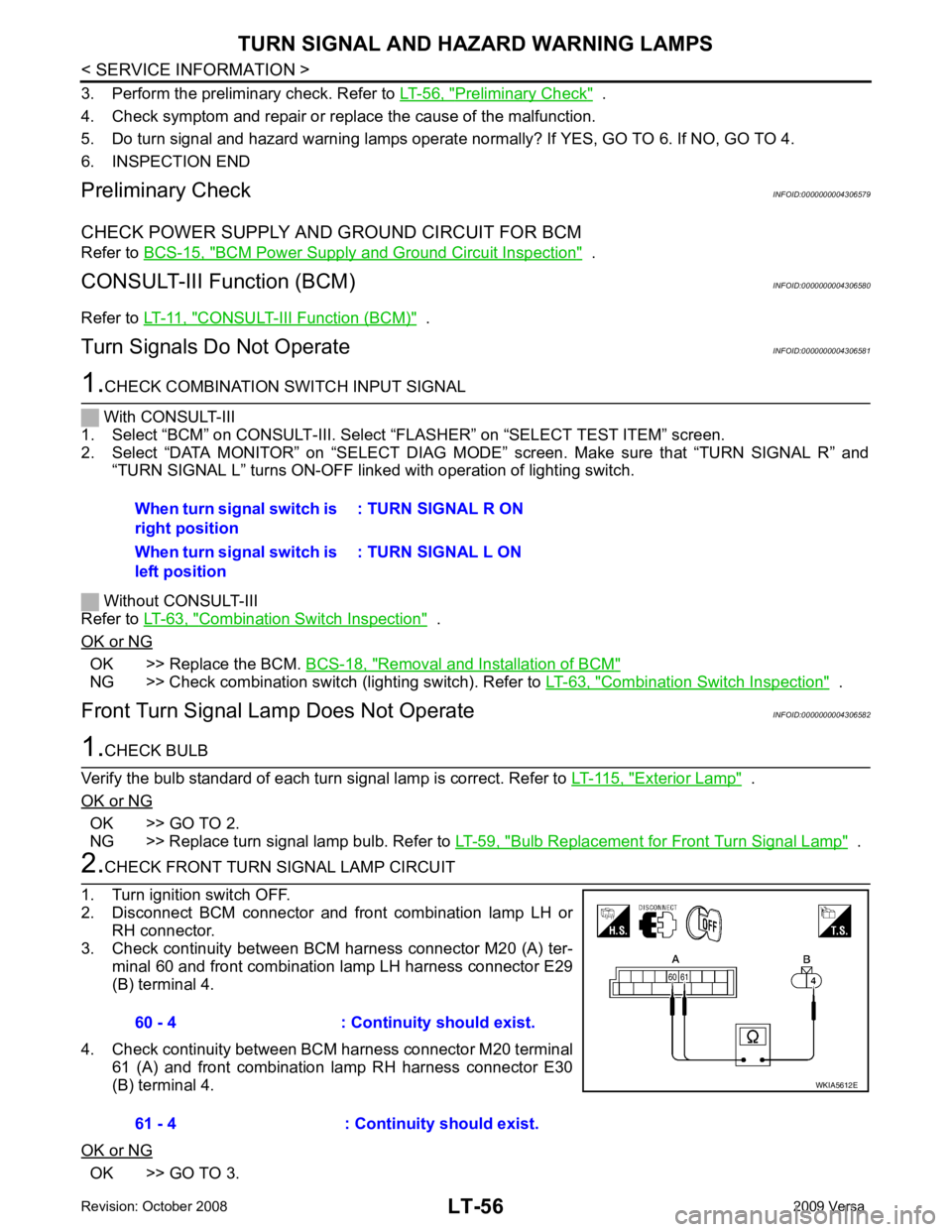
right position : TURN SIGNAL R ON
When turn signal switch is
left position : TURN SIGNAL L ON60 - 4 : Continuity should exist.
61 - 4 : Continuity should exist.
Page 3663 of 4331
LT
N
O P
NG >> Repair harness or connector.
OK >> Inspect connection at front combination lamp.
NG >> Repair harness.
Rear Turn Signal Lamp Does Not Operate INFOID:0000000004306583Exterior Lamp " .
OK or NG OK >> GO TO 2.
NG >> Replace turn signal lamp bulb. Refer to LT-59, " Bulb Replacement for Rear Turn Signal Lamp " .
OK >> GO TO 3.
NG >> Repair harness or connector. OK >> Check rear combination lamp connector for proper con-
nection. Repair as necessary.
NG >> Repair harness or connector. 5 - Ground : Continuity should exist.
5 - Ground : Continuity should exist.
Page 3665 of 4331

LT
N
O P
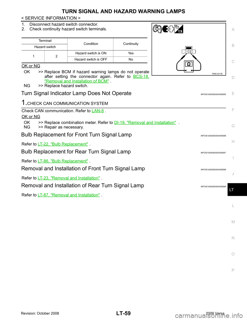
1. Disconnect hazard switch connector.
2. Check continuity hazard switch terminals.
OK or NG OK >> Replace BCM if hazard warning lamps do not operate
after setting the connector again. Refer to BCS-18," Removal and Installation of BCM " .
NG >> Replace hazard switch.
Turn Signal Indicator Lamp Does Not Operate INFOID:0000000004306585 .
OK or NG OK >> Replace combination meter. Refer to
DI-19, " Removal and Installation " .
NG >> Repair as necessary.
Bulb Replacement for Front Turn Signal Lamp INFOID:0000000004306586
Refer to LT-22, " Bulb Replacement " .
Bulb Replacement for Rear Turn Signal Lamp INFOID:0000000004306587
Refer to LT-86, " Bulb Replacement " .
Removal and Installation of Front Turn Signal Lamp INFOID:0000000004306588
Refer to LT-23, " Removal and Installation " .
Removal and Installation of Rear Turn Signal Lamp INFOID:0000000004306589
Refer to LT-87, " Removal and Installation " .
Terminal
Condition Continuity
Hazard switch
1 2 Hazard switch is ON Yes
Hazard switch is OFF No
Page 3666 of 4331
.
2. While pressing pawls (A) in direction as shown, pull lighting and turn signal switch (1) toward LH door and disconnect from the
base.
INSTALLATION
Installation is in the reverse order of removal.
Page 3692 of 4331
Removal and Installation " .
2. Turn bulb socket counterclockwise and unlock it.
3. Remove bulb.
4. Installation is in the reverse order of removal.
SEDAN
1. Remove trunk side finisher. Refer to EI-55, " Removal and Installation " .
2. Turn bulb socket counterclockwise and unlock it.
3. Remove the stop/tail lamp bulb (1), turn signal lamp bulb (2), and the back-up lamp bulb (3).
4. Installation is in the reverse order of removal.