2009 NISSAN LATIO turn signal
[x] Cancel search: turn signalPage 3697 of 4331
LT
N
O P
INTERIOR ROOM LAMP
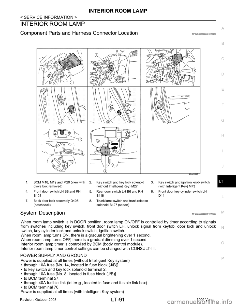
Component Parts and Har ness Connector Location INFOID:0000000004306628
System Description INFOID:0000000004306629
When room lamp switch is in DOOR position, room la mp ON/OFF is controlled by timer according to signals
from switches including key switch, front door switch LH, unlock signal from keyfob, door lock and unlock
switch, key cylinder lock and unlock switch, ignition switch.
When room lamp turns ON, there is a gradual brightening over 1 second.
When room lamp turns OFF, there is a gradual dimming over 1 second.
Interior room lamp timer is controlled by BCM (body control module).
Interior room lamp timer control settings can be changed with CONSULT-III.
POWER SUPPLY AND GROUND Power is supplied at all times (without Intelligent Key system)
• through 10A fuse [No. 14, located in fuse block (J/B)]
• to key switch and key lock solenoid terminal 2,
• through 10A fuse [No. 8, located in fuse block (J/B)]
• to BCM terminal 57,
• through 40A fusible link (letter g , located in fuse and fusible link box)
• to BCM terminal 70.
Power is supplied at all times (with Intelligent Key system) 1. BCM M18, M19 and M20 (view with
glove box removed) 2. Key switch and key lock solenoid
(without Intelligent Key) M27 3. Key switch and ignition knob switch
(with Intelligent Key) M73
4. Front door switch LH B8 and RH B108 5. Rear door switch LH B6 and RH
B116 6. Front door key cylinder switch LH
D14
7. Back door lock assembly D405 (hatchback) 8. Trunk lamp switch and trunk release
solenoid B127 (sedan)
Page 3707 of 4331
LT
N
O P
3. Perform the preliminary check. Refer to
LT-101, " Preliminary Check " .
4. Check symptom and repair or replace the cause of the malfunction.
5. Does the interior room lamp operate norma lly? If YES, GO TO 6. If NO, GO TO 4.
6. Inspection End
Preliminary Check INFOID:0000000004306634
CHECK POWER SUPPLY AND GROUND CIRCUIT FOR BCM Refer to BCS-15, " BCM Power Supply and Ground Circuit Inspection " .
CHECK POWER SUPPLY AND GROUND CIRCUIT FOR IPDM E/R Refer to LT-11, " Preliminary Check " .
CONSULT-III Function (BCM) INFOID:0000000004306635
Refer to LT-11, " CONSULT-III Function (BCM) " .
WORK SUPPORT
Display Item List
Reference between “MODE” and “TIME” for “TURN ON/OFF”
DATA MONITOR
Display Item List Item Description CONSULT-III
SET I/L D −UNLCK INTCON The 30 second operating function of the interior room lamps can be selected
when the front door LH is released (unlocked). ON/OFF
ROOM LAMP ON TIME SET The time in order to escalate illumination can be adjusted when interior room
lamps are turned on. MODE 1 – 7
ROOM LAMP OFF TIME SET The time in order to diminish illumination can be adjusted when interior room
lamps are turned off. MODE 1 – 7
MODE 1 2 3 4 5 6 7
Time (sec.) 0.5 1 2 3 4 5 0 Monitor item Contents
IGN ON SW “ON/OFF” Displays “IGN position (ON)/OFF, ACC position (OFF)” judged from ignition switch signal.
KEY ON SW “ON/OFF” Displays “Key inse rted (ON)/key removed (OFF)” status judged from key switch signal.
DOOR SW - DR “ON/OFF” Displays status of front door LH as judged from front door switch LH signal. (Door is open:
ON/Door is closed: OFF)
DOOR SW - AS “ON/OFF” Displays “Door open (ON)/Door closed (OFF)” status, determined from front door switch
RH signal.
DOOR SW - RR “ON/OFF” Displays “Door open (ON)/Door closed (OFF)” status, determined from rear door switch
RH signal.
DOOR SW - RL “ON/OFF” Displays “Door open (ON)/Door closed (OFF) ” status, determined from rear door switch
LH signal.
TRUNK “ON/OFF” Displays "Back door/Trunk open (ON)/closed (OFF)" status, determined from the back
door switch (hatchback) or the trunk lamp switch (sedan).
LOCK STATUS “ON/OFF” Display status (door is locked: ON/door is unlocked: OFF) of front door lock actuator LH
(unlock sensor) judged from the front door lock actuator LH (unlock sensor) signal.
CDL LOCK SW “ON/OFF” Displays “Door locked (ON)/Door unlocked (OFF) status, determined from locking detec-
tion switch in the front door LH.
CDL UNLOCK SW “ON/OFF” Displays “Door unlocked (OFF)” status, determined from locking detection switch in front
door RH.
Page 3721 of 4331

LT
N
O P
BULB SPECIFICATIONS
Headlamp INFOID:0000000004306645
Exterior Lamp INFOID:0000000004306646
Interior Lamp/Illumination INFOID:0000000004306647
* Always check with the parts department for the latest parts information. Item Wattage (W)
High/Low (Halogen type) 60/55Item Wattage (W)
Front combination lamp Turn signal lamp 21 (amber)
Parking (clearance) lamp 5
Rear combination lamp Stop/Tail lamp 21/5
Turn signal lamp 21 (amber)
Back-up lamp 21
Front fog lamp 35 (H8)
License plate lamp 5
High-mounted stop lamp Hatchback LED
Sedan, rear window 18
Sedan, rear spoiler LED Item Wattage (W)
Glove box lamp 1.4
Map lamp 8
Room lamp 8
Luggage room lamp (Hatchback) 5
Trunk room lamp (Sedan) 5
Vanity mirror lamp *
Page 3923 of 4331
OK >> If the symptom still exists, perform
a complete operational check. Refer to MTC-30, " Operational
Check " . If other symptoms exist, refer to
MTC-22, " How to Perform Trouble Diagnosis for Quick
and Accurate Repair " .
NG >> Repair as necessary.
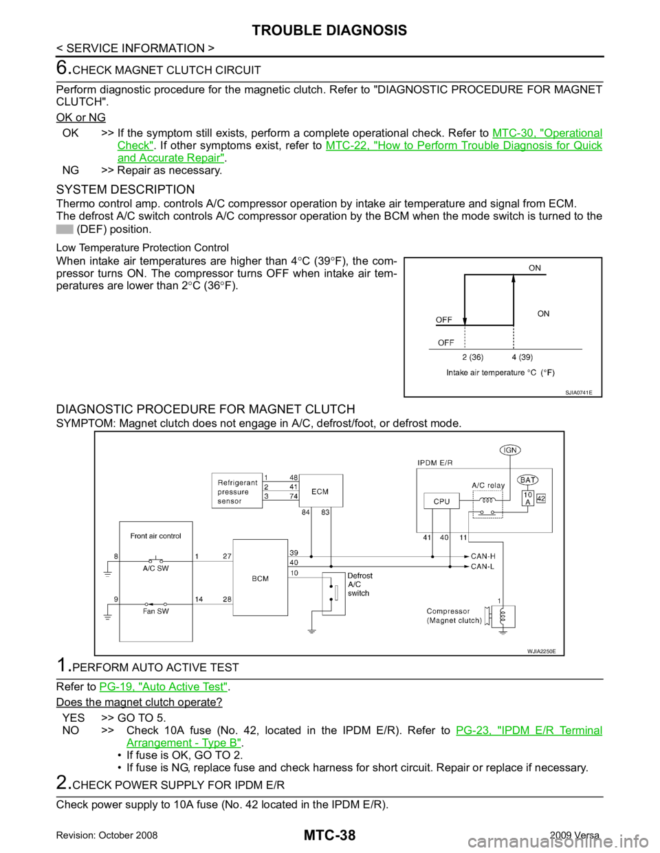
SYSTEM DESCRIPTION
Thermo control amp. controls A/C compressor operat ion by intake air temperature and signal from ECM.
The defrost A/C switch controls A/ C compressor operation by the BCM when the mode switch is turned to the
(DEF) position.
Low Temperature Protection Control
When intake air temperatures are higher than 4 °C (39 °F), the com-
pressor turns ON. The compressor turns OFF when intake air tem-
peratures are lower than 2 °C (36 °F).
DIAGNOSTIC PROCEDURE FOR MAGNET CLUTCH
SYMPTOM: Magnet clutch does not engage in A/C, defrost/foot, or defrost mode.Auto Active Test " .
Does the magnet clutch operate? YES >> GO TO 5.
NO >> Check 10A fuse (No. 42, located in the IPDM E/R). Refer to PG-23, " IPDM E/R Terminal
Arrangement - Type B " .
• If fuse is OK, GO TO 2.
• If fuse is NG, replace fuse and check harness for short circuit. Repair or replace if necessary.
Page 4000 of 4331
PG
N
O P
IPDM E/R STATUS CONTROL
In order to save power, IPDM E/R switches status by itself based on each operating condition.
1. CAN communication status • CAN communication is normally performed with other control units.
• Individual unit control by IPDM E/R is normally performed.
• When sleep request signal is received from BCM, mode is switched to sleep waiting status.
2. Sleep waiting status • Process to stop CAN communication is activated.
• All systems controlled by IPDM E/R are stopped. When 1 second has elapsed after CAN communica-
tion with other control units is st opped, mode switches to sleep status.
3. Sleep status • IPDM E/R operates in low current-consumption mode.
• CAN communication is stopped.
• When a change in CAN communication signal is detec ted, mode switches to CAN communication sta-
tus.
• When a change in ignition switch signal is detect ed, mode switches to CAN communication status.
CAN Communication System Description INFOID:0000000004306656
Refer to LAN-8, " System Diagram " .
Function of Detecting Ig nition Relay Malfunction INFOID:0000000004306657
• When the integrated ignition relay is stuck in a "clo sed contact" position and cannot be turned OFF, IPDM E/
R turns ON tail and parking lamps for 10 mi nutes to indicate IPDM E/R malfunction.
• When the state of the integrated ignition relay does not agree with the state of the ignition switch signal
received via CAN communication, the IPDM E/R activates the tail lamp relay.
NOTE:
When the ignition switch is turned ON, the tail lamps are OFF.
CONSULT-III Function (IPDM E/R) INFOID:0000000004306658
CONSULT-III can display each diagnostic item using the diagnostic test modes shown following.
SELF-DIAGNOSTIC RESULTS
Display Item List Rear window defogger Rear window defogger relay OFF
A/C compressor A/C relay is OFF
Front fog lamps Front fog lamp relay OFF Controlled system Fail-safe mode Ignition switch signal Ignition relay status Tail lamp relay
ON ON —
OFF OFF — ON OFF —
OFF ON ON (10 minutes) IPDM E/R diagnostic Mode Description
SELF-DIAG RESULTS Displays IPDM E/R self-diagnosis results.
DATA MONITOR Displays IPDM E/R input/output data in real time.
CAN DIAG SUPPORT MNTR The result of transmit/receive diagnosis of CAN communication can be read. ACTIVE TEST Operation of electrical loads can be checked by sending drive signal to them.
Page 4002 of 4331
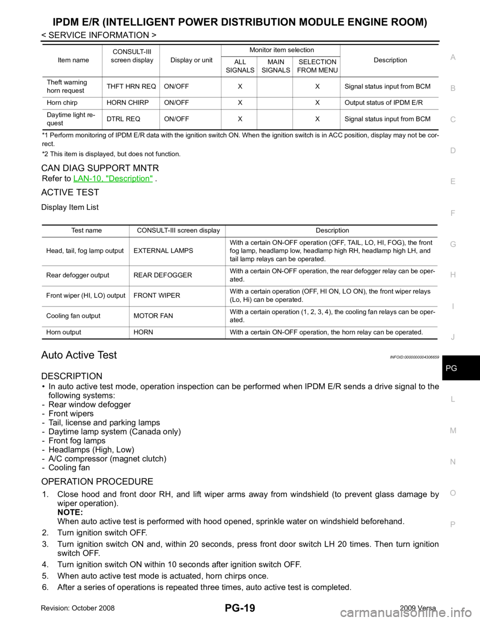
PG
N
O P
*1 Perform monitoring of IPDM E/R data with the ignition switch ON. When the ignition switch is in ACC position, display may no
t be cor-
rect.
*2 This item is displayed, but does not function.
CAN DIAG SUPPORT MNTR Refer to LAN-10, " Description " .
ACTIVE TEST
Display Item List
Auto Active Test INFOID:0000000004306659
DESCRIPTION • In auto active test mode, operation inspection can be performed when IPDM E/R sends a drive signal to the
following systems:
- Rear window defogger
- Front wipers
- Tail, license and parking lamps
- Daytime lamp system (Canada only)
- Front fog lamps
- Headlamps (High, Low)
- A/C compressor (magnet clutch)
- Cooling fan
OPERATION PROCEDURE 1. Close hood and front door RH, and lift wiper arms away from windshield (to prevent glass damage by
wiper operation).
NOTE:
When auto active test is performed with hood opened, sprinkle water on windshield beforehand.
2. Turn ignition switch OFF.
3. Turn ignition switch ON and, within 20 seconds, pre ss front door switch LH 20 times. Then turn ignition
switch OFF.
4. Turn ignition switch ON within 10 seconds after ignition switch OFF.
5. When auto active test mode is actuated, horn chirps once.
6. After a series of operations is repeated th ree times, auto active test is completed.
Theft warning
horn request THFT HRN REQ ON/OFF X X Signal status input from BCM
Horn chirp HORN CHIRP ON/OFF X X O utput status of IPDM E/R
Daytime light re-
quest DTRL REQ ON/OFF X X Signal
status input from BCM
Item name
CONSULT-III
screen display Display or unit Monitor item selection
Description
ALL
SIGNALS MAIN
SIGNALS SELECTION
FROM MENU Test name CONSULT-III screen display Description
Head, tail, fog lamp output EXTERNAL LAMPS With a certain ON-OFF operation (OFF, TAIL, LO, HI, FOG), the front
fog lamp, headlamp low, headlamp high RH, headlamp high LH, and
tail lamp relays can be operated.
Rear defogger output REAR DEFOGGER With a certain ON-OFF operation, the rear defogger relay can be oper-
ated.
Front wiper (HI, LO) output FRONT WIPER With a certain operation (OFF, HI ON, LO ON), the front wiper relays
(Lo, Hi) can be operated.
Cooling fan output MOTOR FAN With a certain operation (1, 2, 3, 4), the cooling fan relays can be oper-
ated.
Horn output HORN With a certain ON-OFF operation, the horn relay can be operated.
Page 4042 of 4331

PG
N
O P
STM CVT Step Motor
STOP/L LT Stop Lamp
TCV AT Torque Converter Clutch Solenoid Valve
TCV CVT Torque Converter Clutch Solenoid Valve
T/LID BL Trunk Lid Opener
T/WARN WT Low Tire Pr essure Warning System
TAIL/L LT Parking, License and Tail Lamps
TPS1 EC Throttle Position Sensor
TPS2 EC Throttle Position Sensor
TPS3 EC Throttle Position Sensor
TURN LT Turn Signal and Hazard Warning Lamps
VEHSEC BL Vehicle Security (Theft Warning) System
VENT/V EC EVAP Canister Vent Control Valve
VSSA/T AT Vehicle Speed Sensor A/T (Revolution Sensor)
VSSMTR AT Vehicle Speed Sensor MTR
WARN DI Warning Lamps
WINDOW GW Power Window
WIP/R WW Rear Wiper and Washer
WIPER WW Front Wiper and Washer
Page 4093 of 4331

Work Support " .
ANTI-PINCH FUNCTION
The CPU (central processing unit) of sunroof motor as sembly monitors the sunroof motor operation and the
sunroof position (fully-closed or other ) by the signals from sunroof motor.
When sunroof motor detects an interruption during the following slide close and tilt down operation, sunroof
switch controls the motor for open and the sunroof will oper ate until it reaches full up position (during tilt down
operation) or 125 mm (4.92 in) or more in an open direction (during slide close operation).
• close operation and tilt down when igniti on switch is in the ON position.
• close operation and tilt down during retained power operation.
INITIALIZATION FAILURE CONDITIONS
Initialization and teaching of system should be conducted if the following conditions exist:
• sunroof will only move in the UP/CLOSE direction, having a step by step motion
• sunroof does not have any auto operation.
INITIALIZATION PROCEDURE
If the sunroof does not close or open automatically, use the following procedure to return sunroof operation to
normal.
1. Press the switch to the UP/CLOSE position to tilt t he sunroof up fully. When the sunroof reaches the full tilt
up position it will back up a few millimeters and stop.
2. Release the UP/CLOSE switch.
3. Within 5 seconds of releasing the UP/CLOSE sw itch, press and hold the UP/CLOSE switch again. The
sunroof will move to the full open position and back to the closed position.
NOTE:
If the UP/CLOSE switch is released anytime during th is teaching process, all learned profile data will be dis-
carded and the procedure will have to be started over.
4. Release the UP/CLOSE switch. Do not disconnect power for at least two seconds. The sunroof is now ini-
tialized and taught.
Initializing procedure is complete. Confirm proper operation of the sunroof (slide open, slide closed, tilt up, tilt
down).
RE-TEACHING CONDITIONS
Re-teaching of system should be conducted if any of the following conditions exist:
• the sunroof is manually operated using the sunroof wrench with the battery discharged or disconnected.
• the sunroof is manually operated using the sunroof wrench with the key switch in the OFF position and
retained power timed out (after approximat ely 45 seconds or with a front door open).
• the sunroof motor assembly is replaced with a new one.
• the sunroof motor is removed from the sunroof assembly and operated before it is reinstalled.