2009 NISSAN LATIO turn signal
[x] Cancel search: turn signalPage 4097 of 4331

System Description " .
3. According to the trouble diagnosis chart, repa ir or replace the cause of the malfunction.
Refer to RF-17, " Trouble Diagnosis Chart by Symptom " .
4. Does sunroof system operate normally? If Yes, GO TO 5. If No, GO TO 3.
5. Inspection End.
CONSULT-III Function (BCM) INFOID:0000000004307400
CONSULT-III can display each diagnostic item us ing the diagnostic test modes shown following.
Terminal
Wire col-
or Item Condition
Voltage
(Approx.)
1 R Sunroof switch (UP/CLOSE) signal Ignition switch ON and sunroof
switch in UP/CLOSE position 0
Ignition switch ON and sunroof
switch in OFF position Battery voltage
5 G Sunroof switch (DOWN/OPEN) signal Ignition switch ON and sunroof
switch in DOWN/OPEN position 0
Ignition switch ON and sunroof
switch in OFF position Battery voltage
7 P BAT power supply — Battery voltage
8 O Vehicle speed signal Speedometer operated [when ve-
hicle speed is approx. 40 km/h (25 MPH)]
9 W RAP signal Ignition switch ON Battery voltage
Within 45 seconds after ignition switch is turned OFF Battery voltage
When front door LH or RH is
opened while retained power is
operating 0
10 B Ground — 0
Page 4098 of 4331

RF
N
O P
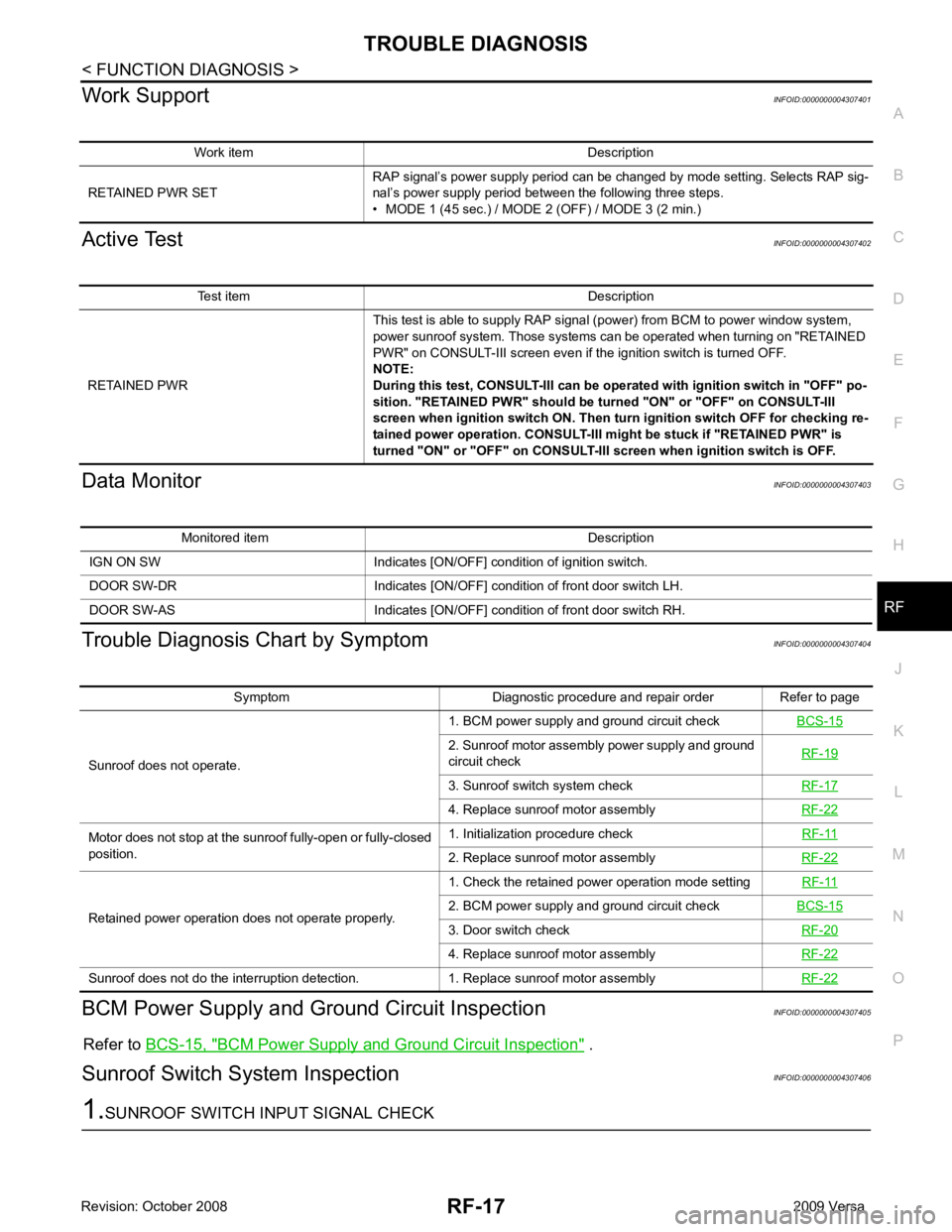
Work Support
INFOID:0000000004307401
Active Test INFOID:0000000004307402
Data Monitor INFOID:0000000004307403
Trouble Diagnosis Chart by Symptom INFOID:0000000004307404
BCM Power Supply and Gr ound Circuit Inspection INFOID:0000000004307405
Refer to BCS-15, " BCM Power Supply and Ground Circuit Inspection " .
Sunroof Switch System Inspection INFOID:0000000004307406Test item Description
RETAINED PWR This test is able to supply RAP signal (power) from BCM to power window system,
power sunroof system. Those systems can be operated when turning on "RETAINED
PWR" on CONSULT-III screen even if the ignition switch is turned OFF.
NOTE:
During this test, CONSULT-III can be operated with ignition switch in "OFF" po-
sition. "RETAINED PWR" should be turned "ON" or "OFF" on CONSULT-III
screen when ignition switch ON. Then turn ignition switch OFF for checking re-
tained power operation. CONSULT-III might be stuck if "RETAINED PWR" is
turned "ON" or "OFF" on CONSULT-III screen when ignition switch is OFF. Symptom Diagnostic procedure and repair order Refer to page
Sunroof does not operate. 1. BCM power supply and ground circuit check
BCS-15 2. Sunroof motor assembly power supply and ground
circuit check RF-19 3. Sunroof switch system check
RF-17 4. Replace sunroof motor assembly
RF-22Motor does not stop at the sunroof fully-open or fully-closed
position. 1. Initialization procedure check
RF-11 2. Replace sunroof motor assembly
RF-22Retained power operation does not operate properly.
1. Check the retained power operation mode setting
RF-11 2. BCM power supply and ground circuit check
BCS-15 3. Door switch check
RF-20 4. Replace sunroof motor assembly
RF-22Sunroof does not do the interruption detection. 1. Replace sunroof motor assembly
RF-22
Page 4227 of 4331

SRS
N
O P
SPIRAL CABLE
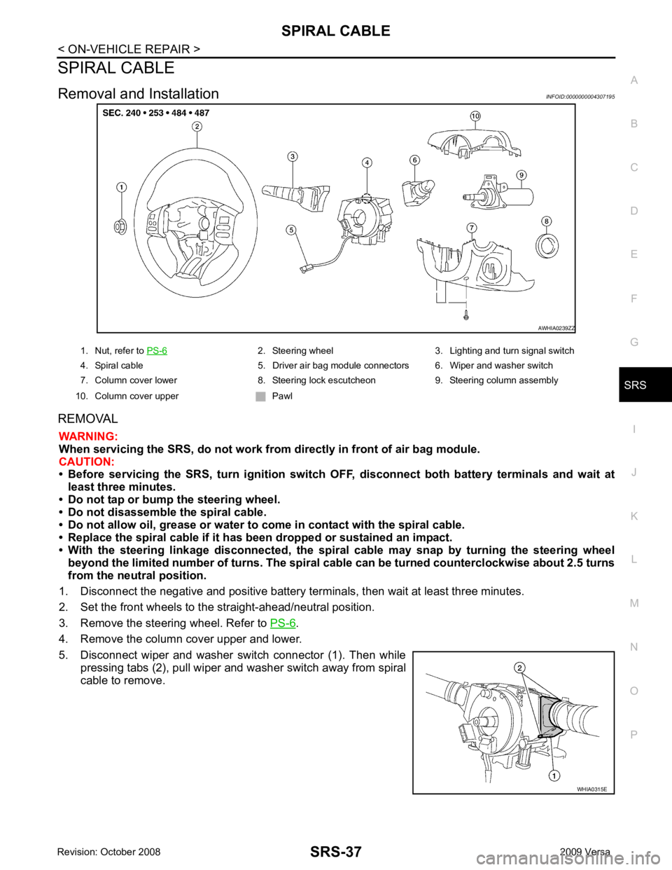
Removal and Installation INFOID:0000000004307195
REMOVAL WARNING:
When servicing the SRS, do not work from directly in front of air bag module.
CAUTION:
• Before servicing the SRS, turn ignition switch OFF, disconnect both battery terminals and wait at
least three minutes.
• Do not tap or bump the steering wheel.
• Do not disassemble the spiral cable.
• Do not allow oil, grease or water to co me in contact with the spiral cable.
• Replace the spiral cable if it has b een dropped or sustained an impact.
• With the steering linkage disconn ected, the spiral cable may snap by turning the steering wheel
beyond the limited number of turns. The spiral cable can be turned counterclockwise about 2.5 turns
from the neutral position.
1. Disconnect the negative and positive battery term inals, then wait at least three minutes.
2. Set the front wheels to the straight-ahead/neutral position.
3. Remove the steering wheel. Refer to PS-6 .
4. Remove the column cover upper and lower.
5. Disconnect wiper and washer switch connector (1). Then while pressing tabs (2), pull wiper and washer switch away from spiral
cable to remove. 2. Steering wheel 3. Lighting and turn signal switch
4. Spiral cable 5. Driver air bag module connectors 6. Wiper and washer switch
7. Column cover lower 8. Steering lock escutcheon 9. Steering column assembly
10. Column cover upper Pawl
Page 4228 of 4331

SRS-38< ON-VEHICLE REPAIR >
SPIRAL CABLE
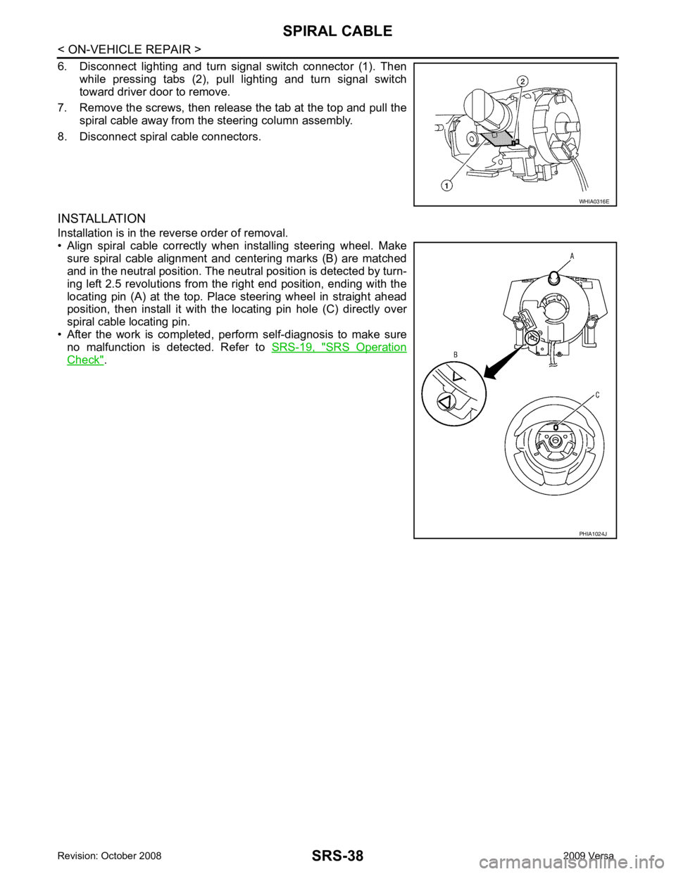
6. Disconnect lighting and turn signal switch connector (1). Then while pressing tabs (2), pull lighting and turn signal switch
toward driver door to remove.
7. Remove the screws, then release the tab at the top and pull the spiral cable away from the steering column assembly.
8. Disconnect spiral cable connectors.
INSTALLATION
Installation is in the reverse order of removal.
• Align spiral cable correctly when installing steering wheel. Make sure spiral cable alignment and centering marks (B) are matched
and in the neutral position. The neutra l position is detected by turn-
ing left 2.5 revolutions from the right end position, ending with the
locating pin (A) at the top. Place steering wheel in straight ahead
position, then install it with the locating pin hole (C) directly over
spiral cable locating pin.
• After the work is completed, perform self-diagnosis to make sure
no malfunction is detected. Refer to SRS-19, " SRS Operation
Check " . WHIA0316E
PHIA1024J
Page 4241 of 4331

STC
N
O P
CONTENTS
STEERING CONTROL SYSTEM
EPS
SERVICE INFORMATION .. ..........................
2
PRECAUTIONS .............................................. .....2
Precaution for Supplemental Restraint System
(SRS) "AIR BAG" and "SEAT BELT PRE-TEN-
SIONER" ............................................................. ......
2
Precaution Necessary fo r Steering Wheel Rota-
tion After Battery Disconnect ............................... ......
2
Service Notice or Precau tion for EPS System ..........3
EPS SYSTEM ... .............................................. .....4
System Description ............................................. ......4
Schematic ........................................................... ......5
CAN Communication ........................................... ......5
TROUBLE DIAGNOSIS ................................. .....6
Fail-Safe Function ............................................... ......6
How to Perform Trouble Diagnosis ..................... ......6
Component Parts Location .................................. ......7
Wiring Diagram - EPS - ... ..........................................8
EPS Control Unit Input/O utput Signal Reference
Value ................................................................... ......
9 EPS Terminal and Reference Value ....................
....10
CONSULT-III Function ( EPS) ..................................11
Symptom Chart .................................................... ....13
TROUBLE DIAGNOSIS FOR SYSTEM ............ 14
DTC C1601 BATTERY VOLT .............................. ....14
DTC C1604 TORQUE SENSOR ......................... ....15
DTC C1606 EPS MOTOR ................................... ....16
DTC C1607 EEPROM ......................................... ....17
DTC C1608 CONTROL UNIT .............................. ....17
DTC C1609 CAN VHCL SPEED ......................... ....18
DTC C1610 CAN ENG RPM ............................... ....19
DTC U1000 CAN COMM CIRCUIT ..................... ....19
Component Inspection ......................................... ....19
TROUBLE DIAGNOSIS FOR SYMPTOMS ...... 21
EPS Warning Lamp Does Not Turn ON ..................21
EPS Warning Lamp Does Not Turn OFF ................21
Steering Wheel Turning Force Is Heavy or Light . ....22
Unbalance Steering Wheel Turning Force and Re-
turn Between Right and Left ................................ ....
23
Unbalance Steering Wheel Turning Force (Torque
Variation) ............................................................. ....
24
Page 4243 of 4331
![NISSAN LATIO 2009 Service Repair Manual PRECAUTIONS
STC-3
< SERVICE INFORMATION >
[EPS] C
D E
F
H I
J
K L
M A
B STC
N
O
P
5. When the repair work is completed, return the ignition switch to the
″LOCK ″ position before con NISSAN LATIO 2009 Service Repair Manual PRECAUTIONS
STC-3
< SERVICE INFORMATION >
[EPS] C
D E
F
H I
J
K L
M A
B STC
N
O
P
5. When the repair work is completed, return the ignition switch to the
″LOCK ″ position before con](/manual-img/5/57359/w960_57359-4242.png)
PRECAUTIONS
STC-3
< SERVICE INFORMATION >
[EPS] C
D E
F
H I
J
K L
M A
B STC
N
O
P
5. When the repair work is completed, return the ignition switch to the
″LOCK ″ position before connecting
the battery cables. (At this time, the steering lock mechanism will engage.)
6. Perform a self-diagnosis check of al l control units using CONSULT-III.
Service Notice or Precaution for EPS System INFOID:0000000004307286
CAUTION:
Check or confirm the following item wh en performing the trouble diagnosis.
• Check any possible causes by interviewing the symptom and it’s condition from the customer if any
malfunction, such as EPS warn ing lamp turns ON, occurs.
• Check if air pressure and size of tires are proper, the specified part is used for the steering wheel,
and control unit is genuine part.
• Check if the connection of steer ing column assembly and steering gear assembly is proper (there is
not looseness of mounting bolts, damage of rods, boots or sealants, and leakage of grease, etc).
• Check if the wheel alignmen t is adjusted properly.
• Check if there is any damage or modification to su spension or body resulting in increased weight or
altered ground clearance.
• Check if installation conditions of each link and suspension are proper.
• Check if the battery voltage is proper
• Check connection conditions of each connector are proper.
• Before connecting or disconnect ing the EPS control unit har-
ness connector, turn ignition switch “OFF” and disconnect
battery ground cable. Because battery voltage is applied to
EPS control unit even if igniti on switch is turned “OFF”.
• When connecting or disconnect ing pin connectors into or
from EPS control unit, take care not to damage pin terminals
(bend or break).
When connecting pin connectors, make sure that there are no
bends or breaks on EPS control unit pin terminal.
• Before replacing EPS control unit, perform EPS control unit input/output signal inspectio n and make sure whether EPS
control unit functions properly or not. Refer to STC-9, " EPS
Control Unit Input/Output Signal Reference Value " . SEF289H
SEF291H
SDIA1848E
Page 4252 of 4331
![NISSAN LATIO 2009 Service Repair Manual DTC C1601
BATTERY VOLT "
TORQUE SENSOR
[C1604] When the torque sensor malfunction assembled in steering column
assembly is detected. STC-15, " DTC C1604
TORQUE SENSOR "
EPS MOTOR
[C1606] When the NISSAN LATIO 2009 Service Repair Manual DTC C1601
BATTERY VOLT "
TORQUE SENSOR
[C1604] When the torque sensor malfunction assembled in steering column
assembly is detected. STC-15, " DTC C1604
TORQUE SENSOR "
EPS MOTOR
[C1606] When the](/manual-img/5/57359/w960_57359-4251.png)
DTC C1601
BATTERY VOLT "
TORQUE SENSOR
[C1604] When the torque sensor malfunction assembled in steering column
assembly is detected. STC-15, " DTC C1604
TORQUE SENSOR "
EPS MOTOR
[C1606] When the motor driver
malfunction of EPS control unit or EPS motor
malfunction is detected. STC-16, " DTC C1606
EPS MOTOR "
EEPROM
[C1607] When the memory (EEPROM) system malfunction is detected in
EPS control unit. STC-17, " DTC C1607
EEPROM "
CONTROL UNIT
[C1608] When the internal malfunction is detected in EPS control unit. STC-17, " DTC C1608
CONTROL UNIT "
CAN VHCL SPEED
[C1609] When the malfunction is detected in vehicle speed signal received
with CAN communication. STC-18, " DTC C1609
CAN VHCL SPEED "
CAN ENG RPM
[C1610] When the malfunction is detected in engine status signal received
with CAN communication. STC-19, " DTC C1610
CAN ENG RPM "
CAN COMM CIRCUIT
[U1000] When EPS control unit is
not transmitting or receiving CAN commu-
nication signal 2 seconds or more. STC-19, " DTC U1000
CAN COMM CIRCUIT "
NO DTC IS DETECTED.
FURTHER TESTING MAY BE RE-
QUIRED. No NG item has been detected. —Monitor item (Unit) Remarks
MOTOR VOL (V) Power supply voltage for EPS control unit is displayed
TORQUE SENSOR (Nm) Steering wheel turning force detected by torque sensor is displayed
MOTOR SIG (A) Current commanded value to EPS motor is displayed
MOTOR CURRENT (A) Current value cons umed by EPS motor is displayed
VEHICLE SPEED (km/h) or (mph) Vehicle speed is displayed from vehicle speed signal with CAN communication
WARNING LAMP (ON/OFF) EPS warning la mp control status is displayed
DERATING STAT (ON/OFF) Protect overload status is displayed
ENGINE STATUS (STOP/RUN) Engine spee d is displayed from engine status signal with CAN communication
Page 4253 of 4331

STC
N
O P
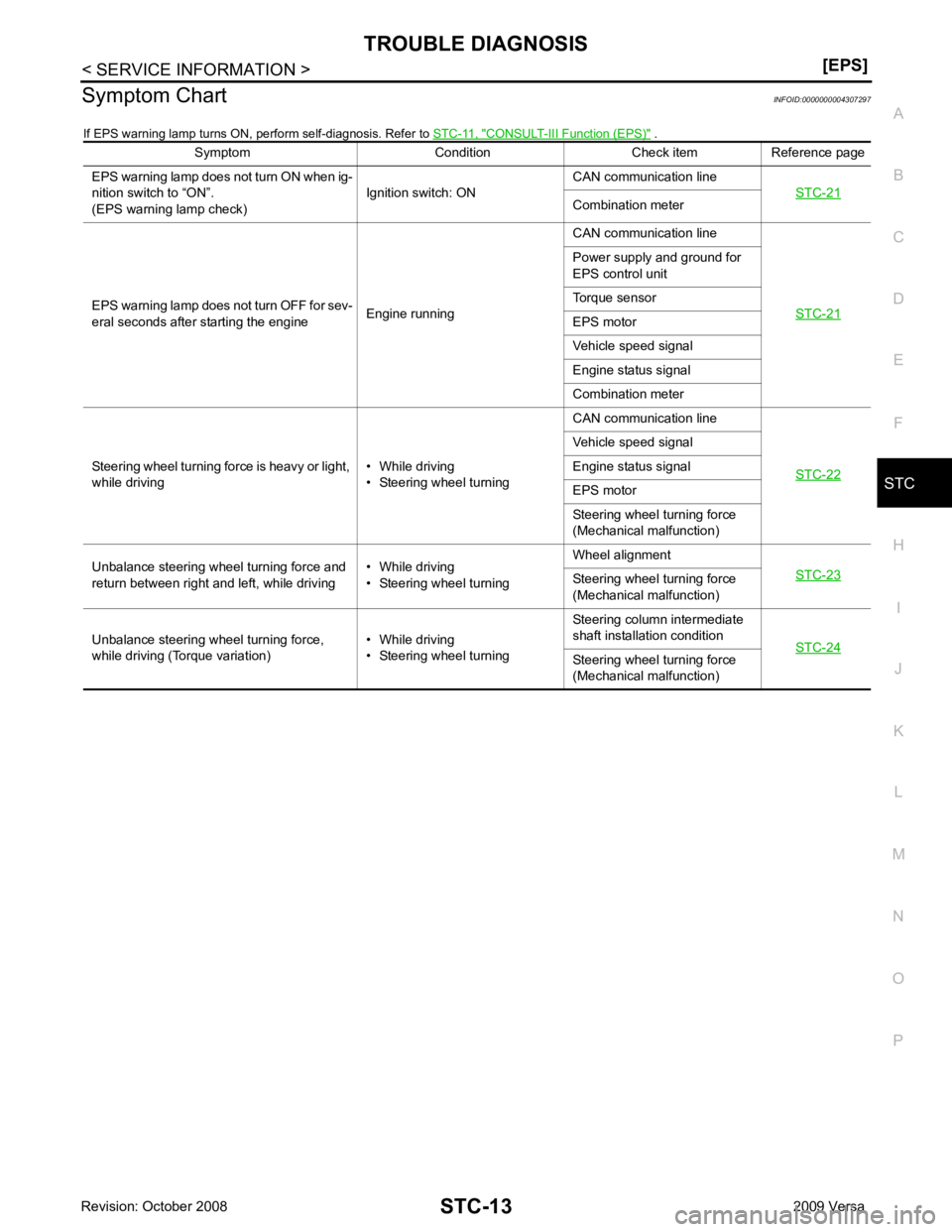
Symptom Chart
INFOID:0000000004307297
If EPS warning lamp turns ON, perform self-diagnosis. Refer to STC-11, " CONSULT-III Function (EPS) " .
Symptom Condition Check item Reference page
EPS warning lamp does not turn ON when ig-
nition switch to “ON”.
(EPS warning lamp check) Ignition switch: ONCAN communication line
STC-21 Combination meter
EPS warning lamp does not turn OFF for sev-
eral seconds after starting the engine Engine runningCAN communication line
STC-21 Power supply and ground for
EPS control unit
Torque sensor
EPS motor
Vehicle speed signal
Engine status signal
Combination meter
Steering wheel turning force is heavy or light,
while driving • While driving
• Steering wheel turning CAN communication line
STC-22 Vehicle speed signal
Engine status signal
EPS motor
Steering wheel turning force
(Mechanical malfunction)
Unbalance steering wheel turning force and
return between right and left, while driving • While driving
• Steering wheel turning Wheel alignment
STC-23 Steering wheel
turning force
(Mechanical malfunction)
Unbalance steering wheel turning force,
while driving (Torque variation) • While driving
• Steering wheel turning Steering column intermediate
shaft installation condition STC-24 Steering wheel
turning force
(Mechanical malfunction)