2009 NISSAN LATIO turn signal
[x] Cancel search: turn signalPage 8 of 4331
AT
N
O
P
N
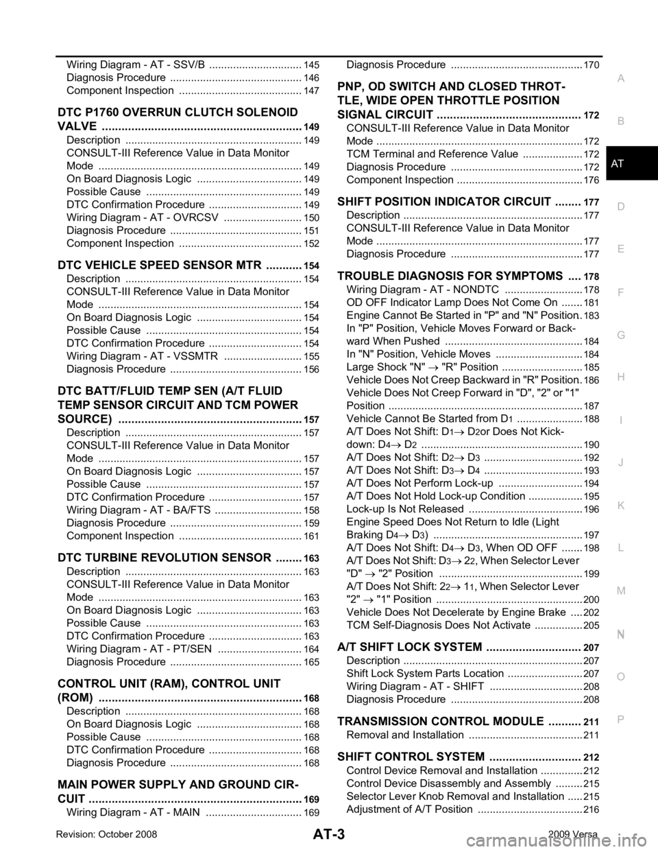
Wiring Diagram - AT -
SSV/B ................................
145
Diagnosis Procedure ........................................... ..146
Component Inspection ........................................ ..147
DTC P1760 OVERRUN CLUTCH SOLENOID
VALVE ............................................................ ..149
Description .......................................................... ..149
CONSULT-III Refe rence Value in Data Monitor
Mode ................................................................... ..
149
On Board Diagnosis Logic .................................. ..149
Possible Cause ................................................... ..149
DTC Confirmation Procedure .............................. ..149
Wiring Diagram - AT - OVRCSV ......................... ..150
Diagnosis Procedure ........................................... ..151
Component Inspection ........................................ ..152
DTC VEHICLE SPEED SENSOR MTR .......... ..154
Description .......................................................... ..154
CONSULT-III Refe rence Value in Data Monitor
Mode ................................................................... ..
154
On Board Diagnosis Logic .................................. ..154
Possible Cause ................................................... ..154
DTC Confirmation Procedure .............................. ..154
Wiring Diagram - AT - VSSMTR ...........................155
Diagnosis Procedure ........................................... ..156
DTC BATT/FLUID TEMP SEN (A/T FLUID
TEMP SENSOR CIRCUIT AND TCM POWER
SOURCE) ....................................................... ..
157
Description .......................................................... ..157
CONSULT-III Refe rence Value in Data Monitor
Mode ................................................................... ..
157
On Board Diagnosis Logic .................................. ..157
Possible Cause ................................................... ..157
DTC Confirmation Procedure .............................. ..157
Wiring Diagram - AT - BA/FTS ............................ ..158
Diagnosis Procedure ........................................... ..159
Component Inspection ........................................ ..161
DTC TURBINE REVOLUTION SENSOR ....... ..163
Description .......................................................... ..163
CONSULT-III Refe rence Value in Data Monitor
Mode ................................................................... ..
163
On Board Diagnosis Logic .................................. ..163
Possible Cause ................................................... ..163
DTC Confirmation Procedure .............................. ..163
Wiring Diagram - AT - PT/SEN ........................... ..164
Diagnosis Procedure ........................................... ..165
CONTROL UNIT (RAM), CONTROL UNIT
(ROM) ............................................................. ..
168
Description .......................................................... ..168
On Board Diagnosis Logic .................................. ..168
Possible Cause ................................................... ..168
DTC Confirmation Procedure .............................. ..168
Diagnosis Procedure ........................................... ..168
MAIN POWER SUPPLY AND GROUND CIR-
CUIT ................................................................ ..169
Wiring Diagram - AT - MAIN ............................... ..169 Diagnosis Procedure ...........................................
..170
PNP, OD SWITCH AND CLOSED THROT-
TLE, WIDE OPEN THROTTLE POSITION
SIGNAL CIRCUI T ............................................ 172
CONSULT-III Reference Va lue in Data Monitor
Mode .................................................................... ..
172
TCM Terminal and Refere nce Value .....................172
Diagnosis Procedure ........................................... ..172
Component Inspection ......................................... ..176
SHIFT POSITION INDICATOR CIRCUIT ........ 177
Description ........................................................... ..177
CONSULT-III Reference Va lue in Data Monitor
Mode .................................................................... ..
177
Diagnosis Procedure ........................................... ..177
TROUBLE DIAGNOSIS FOR SYMPTOMS .... 178
Wiring Diagram - AT - NONDTC ......................... ..178
OD OFF Indicator Lamp Does Not Come On ...... ..181
Engine Cannot Be Started in "P" and "N" Position ..183
In "P" Position, Vehicle Moves Forward or Back-
ward When Pushed ............................................. ..
184
In "N" Position, Vehicle Moves ............................ ..184
Large Shock "N" → "R" Position .......................... ..185
Vehicle Does Not Creep Backward in "R" Position ..186
Vehicle Does Not Creep Forw ard in "D", "2" or "1"
Position ................................................................ ..
187
Vehicle Cannot Be Started from D 1 ..................... ..188
A/T Does Not Shift: D 1→ D 2or Does Not Kick-
down: D 4→ D 2 ..................................................... ..190
A/T Does Not Shift: D 2→ D 3 ................................ ..192
A/T Does Not Shift: D 3→ D 4 ................................ ..193
A/T Does Not Perform Lock-up ........................... ..194
A/T Does Not Hold Lock-up Condition ................. ..195
Lock-up Is Not Released ..................................... ..196
Engine Speed Does Not Return to Idle (Light
Braking D 4→ D 3) ................................................. ..197
A/T Does Not Shift: D 4→ D 3, When OD OFF ...... ..198
A/T Does Not Shift: D 3→ 22, When Selector Lever
"D" → "2" Position ............................................... ..
199
A/T Does Not Shift: 2 2→ 11, When Selector Lever
"2" → "1" Position ................................................ ..
200
Vehicle Does Not Decelerate by Engine Brake ... ..202
TCM Self-Diagnosis Does Not Activate ............... ..205
A/T SHIFT LOCK SYSTEM ............................. 207
Description ........................................................... ..207
Shift Lock System Parts Location ........................ ..207
Wiring Diagram - AT - SHIFT .............................. ..208
Diagnosis Procedure ........................................... ..208
TRANSMISSION CONTROL MODULE .......... 211
Removal and Installation ..................................... ..211
SHIFT CONTROL SYSTEM ............................ 212
Control Device Removal an d Installation ...............212
Control Device Disassembly and Assembly ..........215
Selector Lever Knob Remo val and Installation ......215
Adjustment of A/T Position .................................. ..216
Page 44 of 4331
AT
N
O P
ON BOARD DIAGNOSTIC (OBD) SYSTEM
Introduction INFOID:0000000004305309
A/T system has two self-diagnostic systems.
The first is emission-related on boar d diagnostic system (OBD-II) performed by the TCM in combination with
the ECM. The malfunction is indicated by the MIL (malf unction indicator lamp) and is stored as a DTC in the
ECM memory but not the TCM memory.
The second is the TCM original self-diagnosis indicated by the OD OFF indicator lamp. The malfunction is
stored in the TCM memory. The detected items are ov erlapped with OBD-II self-diagnostic items. For detail,
refer to AT-79, " CONSULT-III Function (TRANSMISSION) " .
OBD-II Function for A/T System INFOID:0000000004305310
The ECM provides emission-related on board diagnostic (O BD-II) functions for the A/T system. One function
is to receive a signal from the TCM used with OBD-rela ted parts of the A/T system. The signal is sent to the
ECM when a malfunction occurs in the corresponding OBD-re lated part. The other function is to indicate a
diagnostic result by means of the MIL (malfunction indica tor lamp) on the instrument panel. Sensors, switches
and solenoid valves are used as sensing elements.
The MIL automatically illuminates in One or Two Trip Detection Logic when a malfunction is sensed in relation
to A/T system parts.
One or Two Trip Detection Logic of OBD-II INFOID:0000000004305311
ONE TRIP DETECTION LOGIC If a malfunction is sensed during the first test drive, the MIL will illuminate and the malfunction will be stored in
the ECM memory as a DTC. The TCM is not provided with such a memory function.
TWO TRIP DETECTION LOGIC When a malfunction is sensed during the first test drive, it is stored in the ECM memory as a 1st trip DTC
(diagnostic trouble code) or 1st trip freeze frame data. At this point, the MIL will not illuminate. — 1st trip
If the same malfunction as that experienced during the fi rst test drive is sensed during the second test drive,
the MIL will illuminate. — 2nd trip
The “trip” in the “One or Two Trip Detection Logic” m eans a driving mode in which self-diagnosis is performed
during vehicle operation.
OBD-II Diagnostic Trouble Code (DTC) INFOID:0000000004305312
HOW TO READ DTC AND 1ST TRIP DTC DTC and 1st trip DTC can be read by the following methods.
( with CONSULT-III or GST) CONSULT-III or GST (Generic Scan Tool) Examples: P0705, P0720 etc.
These DTC are prescribed by SAE J2012.
(CONSULT-III also displays the malfunctioning component or system.)
• 1st trip DTC No. is the same as DTC No.
• Output of the diagnostic troubl e code indicates that the indicated circuit has a malfunction. How-
ever, in case of the Mode II and GST, they do not indicate whether the malfunction is still occurring or
occurred in the past and returned to normal.
CONSULT-III can identify them as shown below, therefore, CONS ULT-III (if available) is recom-
mended.
DTC or 1st trip DTC of a malfunction is displayed in SELF-DIAGNOSTIC RESULTS mode for “ENGINE” with
CONSULT-III. Time data indicates how many times the vehicle was driven after the last detection of a DTC.
If the DTC is being detected curr ently, the time data will be “0”.
If a 1st trip DTC is stored in the ECM, the time data will be “1t”.
Freeze Frame Data and 1st Trip Freeze Frame Data The ECM has a memory function, which stores the driv ing condition such as fuel system status, calculated
load value, engine coolant temperature, short term f uel trim, long term fuel trim, engine speed and vehicle
speed at the moment the ECM detects a malfunction.
Page 48 of 4331
AT
N
O P
�z
: Solenoid ON
× : Solenoid OFF
–: Non-standard condition
Line Pressure Solenoid Valve If non-standard solenoid signal is sent to TCM, line pre ssure solenoid valve is turned OFF to achieve maxi-
mum oil pressure.
Torque Converter Clutch Solenoid Valve If non-standard solenoid signal is sent to TCM, torque conv erter clutch solenoid valve is turned OFF to release
lock-up.
Overrun Clutch Solenoid Valve If non-standard solenoid signal is sent to TCM, overr un clutch solenoid valve is turned OFF to engage overrun
clutch. This will result in more effective engine brake during deceleration.
How to Perform Trouble Diagnosis for Quick and Accurate Repair INFOID:0000000004305316
INTRODUCTION The TCM receives a signal from the vehicle speed sensor, accelera-
tor pedal position sensor or PNP switch and provides shift control or
lock-up control via A/T solenoid valves.
The TCM also communicates with the ECM by means of a signal
sent from sensing elements used wit h the OBD-related parts of the
A/T system for malfunction-diagnostic purposes. The TCM is capa-
ble of diagnosing malfunctioning parts while the ECM can store mal-
functions in its memory.
Input and output signals must always be correct and stable in the
operation of the A/T system. T he A/T system must be in good oper-
ating condition and be free of valve seizure, solenoid valve malfunc-
tion, etc.
It is much more difficult to diagnose a malfunction t hat occurs intermittently rather than continuously. Most
intermittent malfunctions are caused by poor electric c onnections or improper wiring. In this case, careful
checking of suspected circuits may hel p prevent the replacement of good parts.
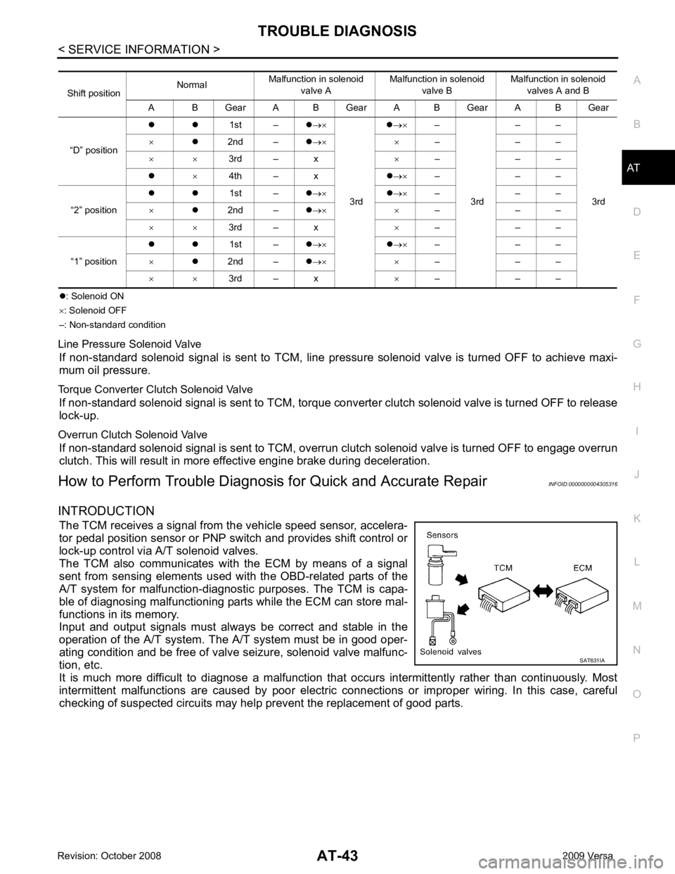
Shift position
Normal
Malfunction in solenoid
valve A Malfunction in solenoid
valve B Malfunction in solenoid
valves A and B
A B Gear A B Gear A B Gear A B Gear
“D” position �z �z
1st –�z→×
3rd �z
→× –
3rd – –
3rd
×
�z2nd – �z→× × – – –
× × 3rd – x ×– – –
�z ×4th – x �z→× – – –
“2” position �z �z
1st –�z→× �z→× – – –
× �z2nd – �z→× × – – –
× × 3rd – x ×– – –
“1” position �z �z
1st –�z→× �z→× – – –
× �z2nd – �z→× × – – –
× × 3rd – x ×– – –
Page 53 of 4331
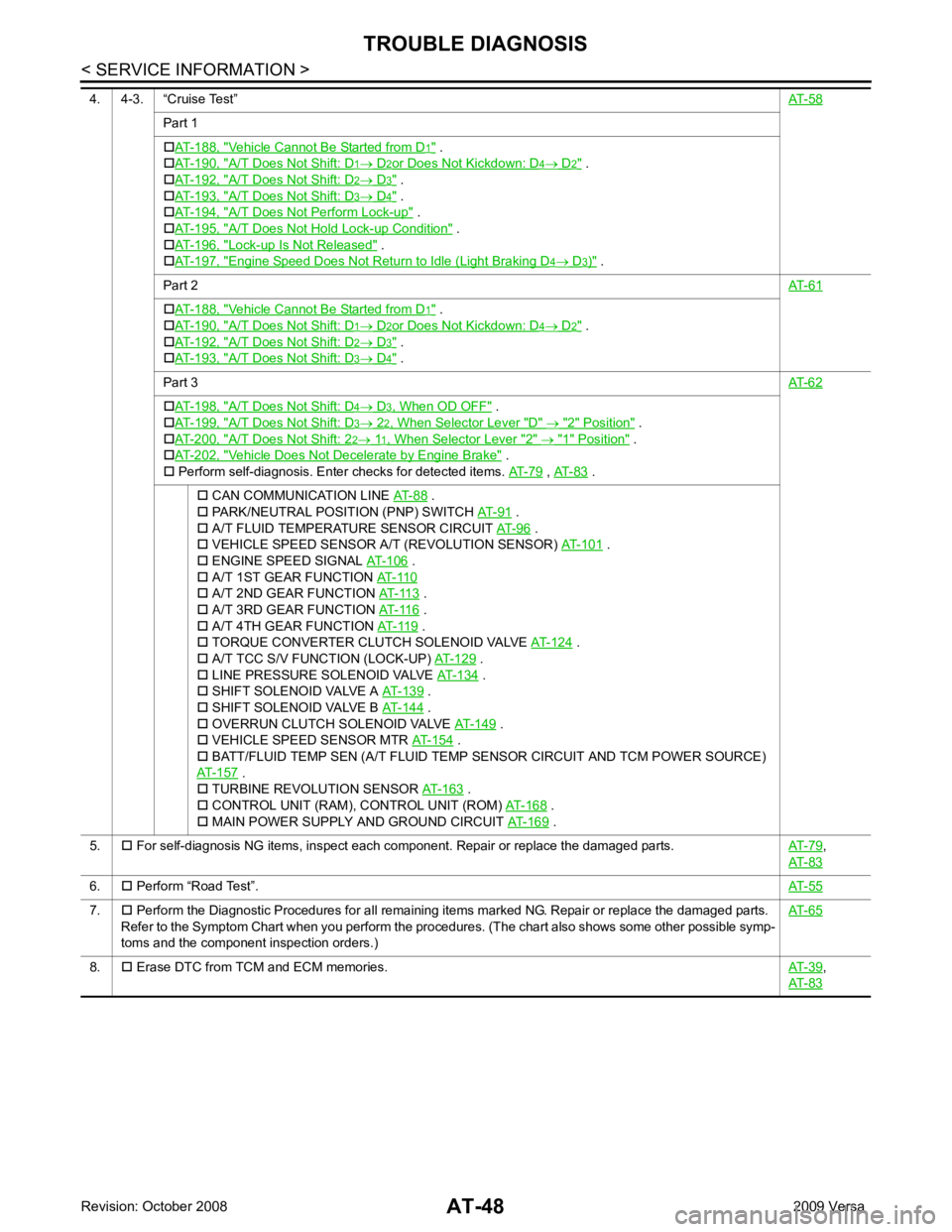
Part 1
�† AT-188, " Vehicle Cannot Be Started from D .
�† AT-190, " A/T Does Not Shift: D .
�† AT-192, " A/T Does Not Shift: D .
�† AT-193, " A/T Does Not Shift: D .
�† AT-194, " A/T Does Not Perform Lock-up " .
�† AT-195, " A/T Does Not Hold
Lock-up Condition " .
�† AT-196, " Lock-up Is Not Released " .
�† AT-197, " Engine Speed Does Not Return to Idle (Light Braking D " .
Part 2 AT-61Vehicle Cannot Be Started from D .
�† AT-190, " A/T Does Not Shift: D .
�† AT-192, " A/T Does Not Shift: D .
�† AT-193, " A/T Does Not Shift: D .
Part 3 AT-62A/T Does Not Shift: D " .
�† AT-199, " A/T Does Not Shift: D " .
�† AT-200, " A/T Does Not Shift: 2 " .
�† AT-202, " Vehicle Does Not Decelerate by Engine Brake " .
�† Perform self-diagnosis. Enter checks for detected items. AT-79 ,
AT-83 .
�† CAN COMMUNICATION LINE AT-88 .
�† PARK/NEUTRAL POSITION (PNP) SWITCH AT-91 .
�† A/T FLUID TEMPERATURE SENSOR CIRCUIT AT-96 .
�† VEHICLE SPEED SENSOR A/T (REVOLUTION SENSOR) AT-101 .
�† ENGINE SPEED SIGNAL AT-106 .
�† A/T 1ST GEAR FUNCTION AT-110 .
�† A/T 3RD GEAR FUNCTION AT-116 .
�† A/T 4TH GEAR FUNCTION AT-119 .
�† TORQUE CONVERTER CLUTCH SOLENOID VALVE AT-124 .
�† A/T TCC S/V FUNCTION (LOCK-UP) AT-129 .
�† LINE PRESSURE SOLENOID VALVE AT-134 .
�† SHIFT SOLENOID VALVE A AT-139 .
�† SHIFT SOLENOID VALVE B AT-144 .
�† OVERRUN CLUTCH SOLENOID VALVE AT-149 .
�† VEHICLE SPEED SENSOR MTR AT-154 .
�† BATT/FLUID TEMP SEN (A/T FLUID TEMP SENSOR CIRCUIT AND TCM POWER SOURCE)
AT-157 .
�† TURBINE REVOLUTION SENSOR AT-163 .
�† CONTROL UNIT (RAM), CONTROL UNIT (ROM) AT-168 .
�† MAIN POWER SUPPLY AND GROUND CIRCUIT AT-169 .
5. �† For self-diagnosis NG items, inspect each component. Repair or replace the damaged parts. AT-79 ,
AT-83 6.
�† Perform “Road Test”. AT-557.
�† Perform the Diagnostic Procedures for all remaining items marked NG. Repair or replace the damaged parts.
Refer to the Symptom Chart when you perform the procedures. (The chart also shows some other possible symp-
toms and the component inspection orders.) AT-658.
�† Erase DTC from TCM and ECM memories. AT-39 ,
AT-83
Page 89 of 4331

AT-84< SERVICE INFORMATION >
TROUBLE DIAGNOSIS
Description
If a malfunction occurs in electrical system, turning igni tion switch ON will illuminate OD OFF indicator lamp for
2 seconds. To detect a malfunction, entering a self-diagnosis start signal retrieves information on malfunctions
from memory and indicates malfunction by blinking OD OFF indicator lamp.
Diagnostic Procedure 1.
CHECK OD OFF INDICATOR LAMP
1. Park vehicle on flat surface.
2. Move selector lever to “P” position.
3. Turn ignition switch OFF. Wait at least 5 seconds.
4. Turn ignition switch ON. (Do not start engine.)
Does OD OFF indicator lamp come on about 2 seconds? YES >> GO TO 2.
NO >> Stop procedure. Perform AT-181, " OD OFF Indicator
Lamp Does Not Come On " before proceeding.
2.
JUDGEMENT PROCEDURE STEP 1
1. Turn ignition switch OFF.
2. Keep pressing shift lock release button.
3. Move selector lever from “P” to “D” position.
4. Turn ignition switch ON. (Do not start engine.)
5. Keep pressing overdrive control switch while OD OF F indicator lamp is lighting up for 2 seconds. (OD
OFF indicator lamp is on.)
6. Keep pressing overdrive control switch and shift select or lever to the “2” position. (OD OFF indicator lamp
is on.)
7. Stop pressing overdrive control switch. (OD OFF indicator lamp is on.)
8. Shift selector lever to the “1” position. (OD OFF indicator lamp is on.)
9. Keep pressing overdrive control switch. (OD OFF indicator lamp is off.)
10. Depress accelerator pedal fully while pressing overdrive control switch.
>> GO TO 3. 3.
CHECK SELF-DIAGNOSIS CODE
Check OD OFF indicator lamp. Refer to "Judgement of Self-diagnosis Code" .
>>DIAGNOSIS END
Judgement of Self-diagnosis Code SCIA5472E
SCIA7140E
Page 92 of 4331
AT
N
O P
t
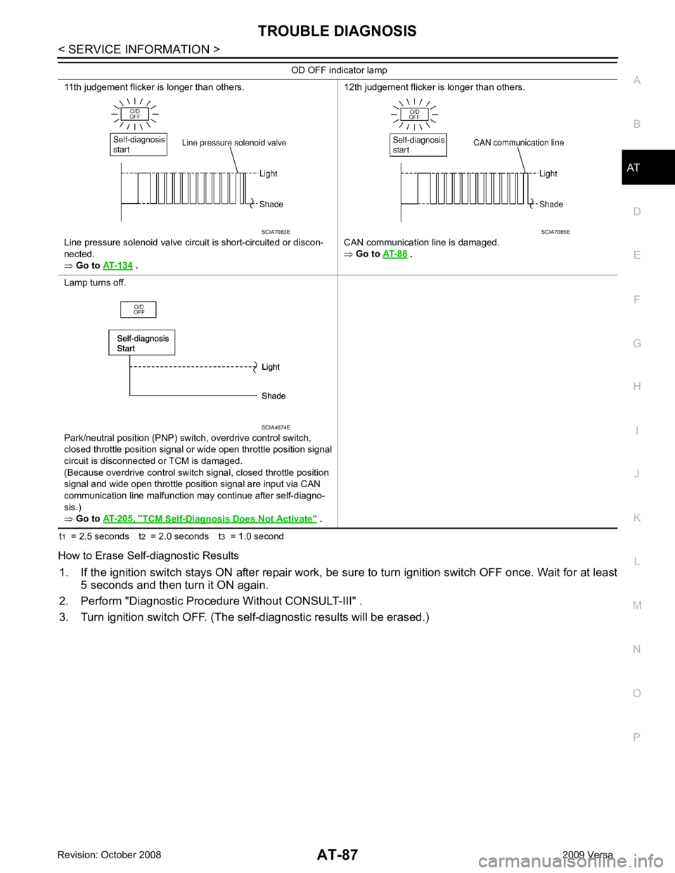
1 = 2.5 seconds t 2 = 2.0 seconds t 3 = 1.0 second
How to Erase Self-diagnostic Results 1. If the ignition switch stays ON after repair work, be su re to turn ignition switch OFF once. Wait for at least
5 seconds and then turn it ON again.
2. Perform "Diagnostic Procedure Without CONSULT-III" .
3. Turn ignition switch OFF. (The self-diagnostic results will be erased.) 11th judgement flicker is longer than others.
Line pressure solenoid valve circuit is short-circuited or discon-
nected.
⇒ Go to AT-134 .
12th judgement flicker is longer than others.
CAN communication line is damaged.
⇒ Go to AT-88 .
Lamp turns off.
Park/neutral position (PNP) switch, overdrive control switch,
closed throttle position signal or wide open throttle position signal
circuit is disconnected or TCM is damaged.
(Because overdrive control switch signal, closed throttle position
signal and wide open throttle position signal are input via CAN
communication line malfunction may continue after self-diagno-
sis.)
⇒ Go to AT-205, " TCM Self-Diagnosis
Does Not Activate " .
OD OFF indicator lamp
Page 96 of 4331
AT
N
O P
DTC P0705 PARK/NEUTRAL POSITION (PNP) SWITCH
Description INFOID:0000000004305338
• The PNP switch assembly includes a transaxle range switch.
• The transaxle range switch detects the selector lever position and sends a signal to the TCM.
CONSULT-III Reference Val ue in Data Monitor Mode INFOID:0000000004305339
On Board Diagnosis Logic INFOID:0000000004305340
• This is an OBD-II self-diagnostic item.
• Diagnostic trouble code “P0705 PNP SW/CIRC” with CONS ULT-III is detected when TCM does not receive
the correct voltage signal from the switch based on the gear position.
Possible Cause INFOID:0000000004305341
• Harness or connectors [The PNP switch circuit is open or shorted.]
• PNP switch
DTC Confirmation Procedure INFOID:0000000004305342
CAUTION:
• Always drive vehicle at a safe speed.
• If performing this “DTC Confirmation Procedure” again, always turn ignition switch OFF and wait at
least 10 seconds before continuing.
After the repair, perform the following procedure to confirm the malfunction is eliminated.
WITH CONSULT-III
1. Turn ignition switch ON. (Do not start engine.)
2. Select “DATA MONITOR” mode for “TRANSMISSION” with CONSULT-III.
3. Touch “START”.
4. Start engine and maintain the following conditions for at least 5 consecutive seconds.
VEHICLE SPEED: 10 km/h (6 MPH) or more
THROTTLE POSI: More than 1.0/8
SLCT LVR POSI: “D” position
5. If the check result is NG, go to AT-93, " Diagnosis Procedure " .
WITH GST
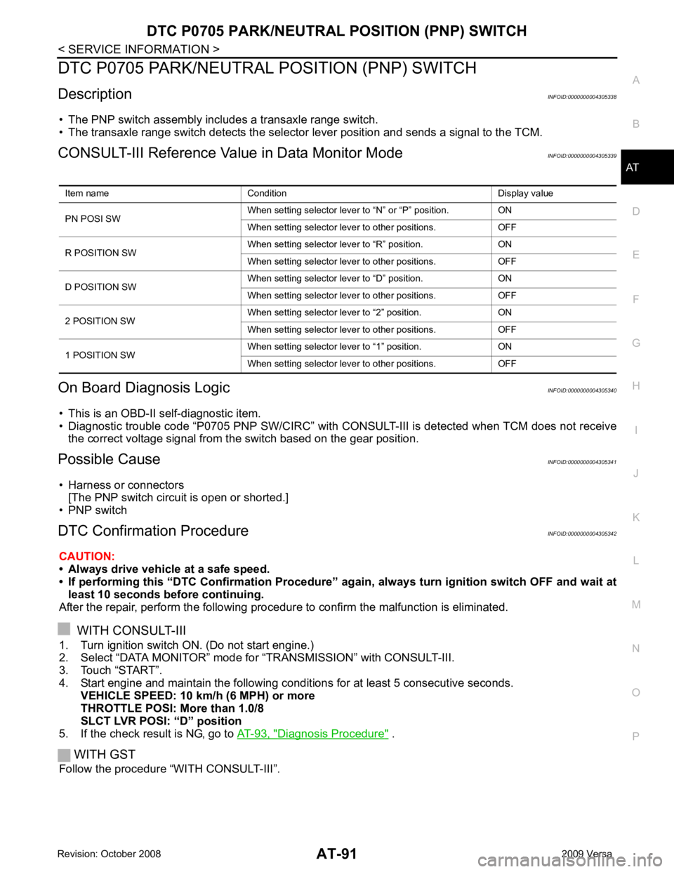
Follow the procedure “WITH CONSULT-III”. Item name Condition Display value
PN POSI SW When setting selector lever
to “N” or “P” position. ON
When setting selector lever to other positions. OFF
R POSITION SW When setting selector lever to “R” position. ON
When setting selector lever to other positions. OFF
D POSITION SW When setting selector lever to “D” position. ON
When setting selector lever to other positions. OFF
2 POSITION SW When setting selector lever to “2” position. ON
When setting selector lever to other positions. OFF
1 POSITION SW When setting selector lever to “1” position. ON
When setting selector lever to other positions. OFF
Page 106 of 4331
AT
N
O P
DTC P0720 VEHICLE SPEED SENS
OR A/T (REVOLUTION SENSOR)
Description INFOID:0000000004305354
The revolution sensor detects the revolution of the id ler gear parking pawl lock gear and emits a pulse signal.
The pulse signal is sent to the TCM which converts it into vehicle speed.
CONSULT-III Reference Val ue in Data Monitor Mode INFOID:0000000004305355
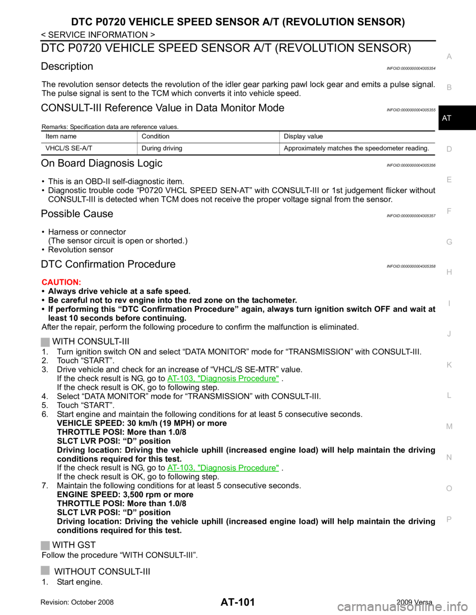
Remarks: Specification data are reference values.
On Board Diagnosis Logic INFOID:0000000004305356
• This is an OBD-II self-diagnostic item.
• Diagnostic trouble code “P0720 VHCL SPEED SEN-AT” with CONSULT-III or 1st judgement flicker without
CONSULT-III is detected when TCM does not rece ive the proper voltage signal from the sensor.
Possible Cause INFOID:0000000004305357
• Harness or connector (The sensor circuit is open or shorted.)
• Revolution sensor
DTC Confirmation Procedure INFOID:0000000004305358
CAUTION:
• Always drive vehicle at a safe speed.
• Be careful not to rev engine into the red zone on the tachometer.
• If performing this “DTC Confirmation Procedure” again, always turn ignition switch OFF and wait at
least 10 seconds before continuing.
After the repair, perform the following procedure to confirm the malfunction is eliminated.
WITH CONSULT-III
1. Turn ignition switch ON and select “DATA MO NITOR” mode for “TRANSMISSION” with CONSULT-III.
2. Touch “START”.
3. Drive vehicle and check for an in crease of “VHCL/S SE-MTR” value.
If the check result is NG, go to AT-103, " Diagnosis Procedure " .
If the check result is OK, go to following step.
4. Select “DATA MONITOR” mode for “TRANSMISSION” with CONSULT-III.
5. Touch “START”.
6. Start engine and maintain the following conditions for at least 5 consecutive seconds. VEHICLE SPEED: 30 km/h (19 MPH) or more
THROTTLE POSI: More than 1.0/8
SLCT LVR POSI: “D” position
Driving location: Driving the vehic le uphill (increased engine load) will help maintain the driving
conditions required for this test.
If the check result is NG, go to AT-103, " Diagnosis Procedure " .
If the check result is OK, go to following step.
7. Maintain the following conditions for at least 5 consecutive seconds. ENGINE SPEED: 3,500 rpm or more
THROTTLE POSI: More than 1.0/8
SLCT LVR POSI: “D” position
Driving location: Driving the vehic le uphill (increased engine load) will help maintain the driving
conditions required for this test.
WITH GST
Follow the procedure “WITH CONSULT-III”.
WITHOUT CONSULT-III
1. Start engine. Item name Condition Display value
VHCL/S SE-A/T During driving Approxima tely matches the speedometer reading.