2009 NISSAN LATIO turn signal
[x] Cancel search: turn signalPage 178 of 4331
PNP, OD SWITCH AND CLOSED THRO
TTLE, WIDE OPEN THROTTLE POSI-
TION SIGNAL CIRCUIT
AT-173
< SERVICE INFORMATION >
D
E
F
G H
I
J
K L
M A
B AT
N
O P 2.
CHECK PNP SWITCH CIRCUIT
With CONSULT-III
1. Turn ignition switch ON. (Do not start engine.)
2. Select “TCM INPUT SIGNALS” in “DATA MONI TOR” mode for “TRANSMISSION” with CONSULT-III.
3. Read out “P·N”, “R”, “D”, “2” and “1” position switches moving selector lever to each position.
OK or NG OK >> GO TO 4.
NG >> Check PNP switch circuit. Refer to AT-91 .
3.
CHECK PNP SWITCH CIRCUIT
Without CONSULT-III
1. Turn ignition switch ON. (Do not start engine.)
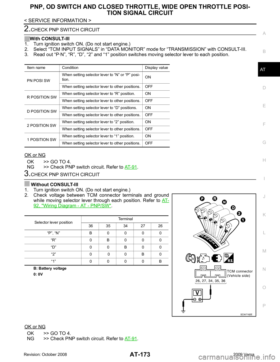
2. Check voltage between TCM connector terminals and ground while moving selector lever through each position. Refer to AT-92, " Wiring Diagram - AT - PNP/SW " .
B: Battery voltage
0: 0V
OK or NG OK >> GO TO 4.
NG >> Check PNP switch circuit. Refer to AT-91 .
Item name Condition Display value
PN POSI SW When setting selector le
ver to “N” or “P” posi-
tion. ON
When setting selector lever to other positions. OFF
R POSITION SW When setting selector lever to “R” position. ON
When setting selector lever to other positions. OFF
D POSITION SW When setting selector lever to “D” positions. ON
When setting selector lever to other positions. OFF
2 POSITION SW When setting selector lever to “2” position. ON
When setting selector lever to other positions. OFF
1 POSITION SW When setting selector lever to “1” position. ON
When setting selector lever to other positions. OFF Selector lever position
Terminal
36 35 34 27 26
“P”, “N” B 0 0 0 0 “R” 0 B 0 0 0
“D” 0 0 B 0 0 “2” 0 0 0 B 0
“1” 0 0 0 0 B SCIA7162E
Page 179 of 4331
AT-174< SERVICE INFORMATION >
PNP, OD SWITCH AND CLOSED THRO
TTLE, WIDE OPEN THROTTLE POSI-
TION SIGNAL CIRCUIT 4.
CHECK PNP SWITCH
1. Turn ignition switch OFF.
2. Disconnect PNP switch harness connector.
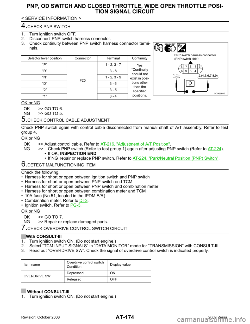
3. Check continuity between PNP switch harness connector termi- nals.
OK or NG OK >> GO TO 6.
NG >> GO TO 5. 5.
CHECK CONTROL CABLE ADJUSTMENT
Check PNP switch again with control cable disconnected from manual shaft of A/T assembly. Refer to test
group 4.
OK or NG OK >> Adjust control cable. Refer to
AT-216, " Adjustment of A/T Position " .
NG >> Check PNP switch (Refer to test group 1) again after adjusting PNP switch (Refer to AT-224 ).
• If OK, INSPECTION END
• If NG, repair or replace PNP switch. Refer to AT-224, " Park/Neutral Position (PNP) Switch " .
6.
DETECT MALFUNCTIONING ITEM
Check the following.
• Harness for short or open between ignition switch and PNP switch
• Harness for short or open between PNP switch and TCM
• Harness for short or open between PNP switch and combination meter
• Harness for short or open between combination meter and TCM
• 10A fuse (No.51, located in the IPDM E/R)
• Combination meter. Refer to DI-3 .
• Ignition switch. Refer to PG-3 .
OK or NG OK >> GO TO 7.
NG >> Repair or replace damaged parts. 7.
CHECK OVERDRIVE CONTROL SWITCH CIRCUIT
With CONSULT-III
1. Turn ignition switch ON. (Do not start engine.)
2. Select “TCM INPUT SIGNALS” in “DATA MONITO R” mode for “TRANSMISSION” with CONSULT-III.
3. Read out “OVERDRIVE SW”. Check the signal of ov erdrive control switch is indicated properly.
Without CONSULT-III
1. Turn ignition switch ON. (Do not start engine.) Selector lever position Connector Terminal Continuity
“P”
F251 - 2, 3 - 7
Yes
*Continuity
should not
exist in posi-
tions other than the
specified
positions.
“R” 3 - 8
“N” 1 - 2, 3 - 9
“D” 3 - 6 “2” 3 - 5
“1” 3 - 4 SCIA5588E
Item name
Overdrive control switch
Condition Display value
OVERDRIVE SW Depressed ON
Released OFF
Page 204 of 4331
TROUBLE DIAGNOSIS FOR SYMPTOMS
AT-199
< SERVICE INFORMATION >
D
E
F
G H
I
J
K L
M A
B AT
N
O P
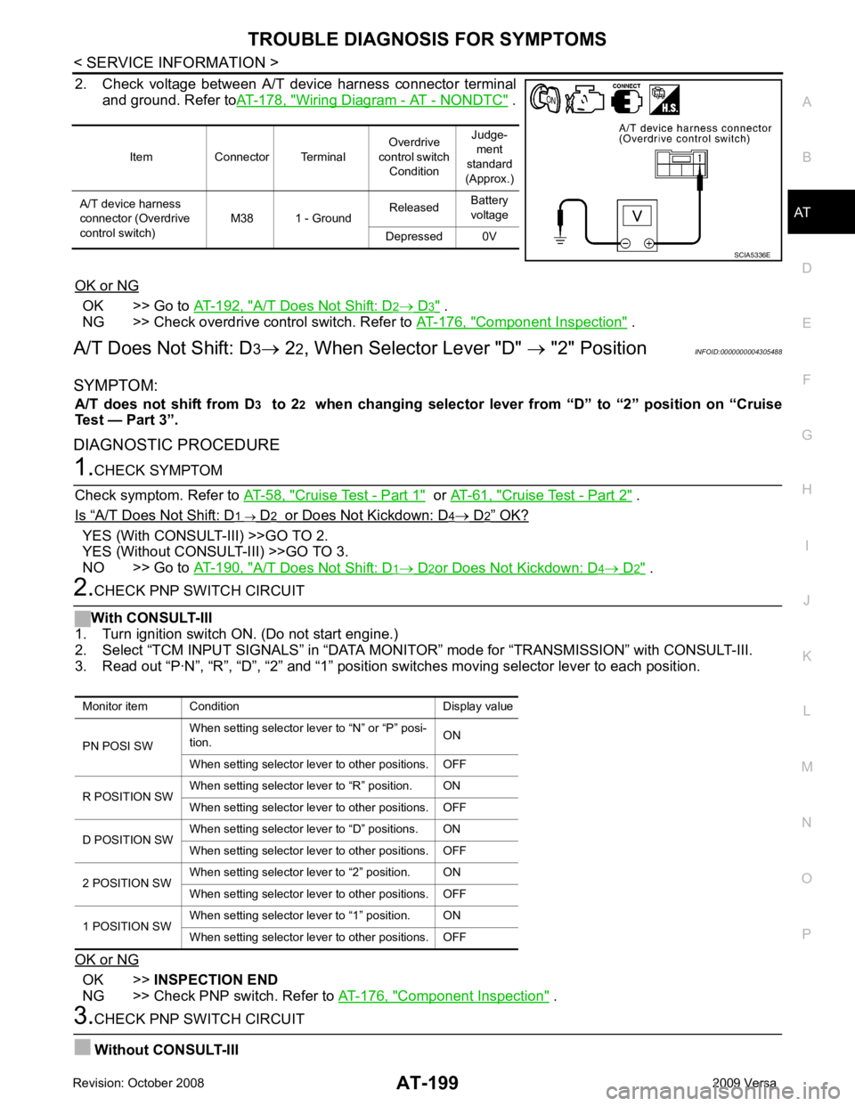
2. Check voltage between A/T device harness connector terminal
and ground. Refer to AT-178, " Wiring Diagram - AT - NONDTC " .
OK or NG OK >> Go to
AT-192, " A/T Does Not Shift: D 2 → D 3 " .
NG >> Check overdrive control switch. Refer to AT-176, " Component Inspection " .
A/T Does Not Shift: D 3→ 22, When Selector Lever "D" → "2" Position INFOID:0000000004305488
SYMPTOM: A/T does not shift from D 3 to 2 2 when changing selector lever from “D” to “2” position on “Cruise
Test — Part 3”.
DIAGNOSTIC PROCEDURE 1.
CHECK SYMPTOM
Check symptom. Refer to AT-58, " Cruise Test - Part 1 " or
AT-61, " Cruise Test - Part 2 " .
Is “ A/T Does Not Shift: D 1 → D 2 or Does Not Kickdown: D 4 → D 2 ” OK?
YES (With CONSULT-III) >>GO TO 2.
YES (Without CONSULT-III) >>GO TO 3.
NO >> Go to AT-190, " A/T Does Not Shift: D 1 → D 2 or Does Not Kickdown: D 4 → D 2 " .
2.
CHECK PNP SWITCH CIRCUIT
With CONSULT-III
1. Turn ignition switch ON. (Do not start engine.)
2. Select “TCM INPUT SIGNALS” in “DATA MONI TOR” mode for “TRANSMISSION” with CONSULT-III.
3. Read out “P·N”, “R”, “D”, “2” and “1” position switches moving selector lever to each position.
OK or NG OK >>
INSPECTION END
NG >> Check PNP switch. Refer to AT-176, " Component Inspection " .
3.
CHECK PNP SWITCH CIRCUIT
Without CONSULT-III Item Connector Terminal
Overdrive
control switch Condition Judge-
ment
standard
(Approx.)
A/T device harness
connector (Overdrive
control switch) M38 1 - Ground
Released
Battery
voltage
Depressed 0V SCIA5336E
Monitor item Condition Display value
PN POSI SW When setting selector le
ver to “N” or “P” posi-
tion. ON
When setting selector lever to other positions. OFF
R POSITION SW When setting selector lever to “R” position. ON
When setting selector lever to other positions. OFF
D POSITION SW When setting selector lever to “D” positions. ON
When setting selector lever to other positions. OFF
2 POSITION SW When setting selector lever to “2” position. ON
When setting selector lever to other positions. OFF
1 POSITION SW When setting selector lever to “1” position. ON
When setting selector lever to other positions. OFF
Page 205 of 4331
AT-200< SERVICE INFORMATION >
TROUBLE DIAGNOSIS FOR SYMPTOMS
1. Turn ignition switch ON. (Do not start engine.)
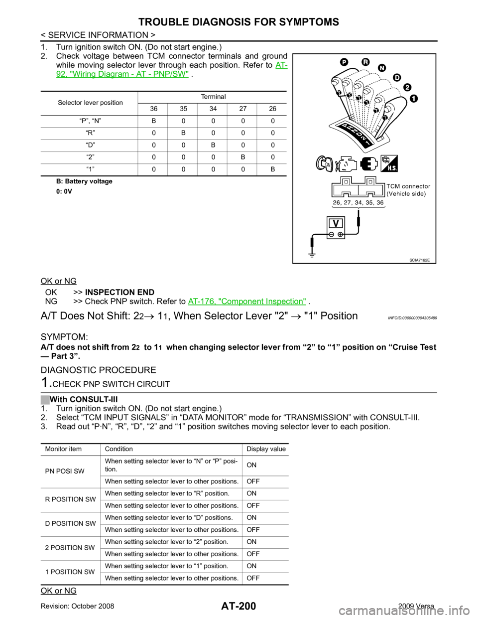
2. Check voltage between TCM connector terminals and ground while moving selector lever through each position. Refer to AT-92, " Wiring Diagram - AT - PNP/SW " .
B: Battery voltage
0: 0V
OK or NG OK >>
INSPECTION END
NG >> Check PNP switch. Refer to AT-176, " Component Inspection " .
A/T Does Not Shift: 2 2→ 11, When Selector Lever "2" → "1" Position INFOID:0000000004305489
SYMPTOM:
A/T does not shift from 2 2 to 1 1 when changing selector lever from “2” to “1” position on “Cruise Test
— Part 3”.
DIAGNOSTIC PROCEDURE 1.
CHECK PNP SWITCH CIRCUIT
With CONSULT-III
1. Turn ignition switch ON. (Do not start engine.)
2. Select “TCM INPUT SIGNALS” in “DATA MONITO R” mode for “TRANSMISSION” with CONSULT-III.
3. Read out “P·N”, “R”, “D”, “2” and “1” position switches moving selector lever to each position.
OK or NG Selector lever position
Terminal
36 35 34 27 26
“P”, “N” B 0 0 0 0 “R” 0 B 0 0 0
“D” 0 0 B 0 0 “2” 0 0 0 B 0
“1” 0 0 0 0 B SCIA7162E
Monitor item Condition Display value
PN POSI SW When setting selector le
ver to “N” or “P” posi-
tion. ON
When setting selector lever to other positions. OFF
R POSITION SW When setting selector lever to “R” position. ON
When setting selector lever to other positions. OFF
D POSITION SW When setting selector lever to “D” positions. ON
When setting selector lever to other positions. OFF
2 POSITION SW When setting selector lever to “2” position. ON
When setting selector lever to other positions. OFF
1 POSITION SW When setting selector lever to “1” position. ON
When setting selector lever to other positions. OFF
Page 207 of 4331
AT-202< SERVICE INFORMATION >
TROUBLE DIAGNOSIS FOR SYMPTOMS
- Shift valve A
- Shift solenoid valve A
- Overrun clutch control valve
- Overrun clutch solenoid valve
3. Disassemble A/T. Refer to AT-256, " Disassembly " .
4. Check the following items:
- Servo piston assembly
- Brake band
OK or NG OK >> GO TO 7.
NG >> Repair or replace damaged parts. 7.
CHECK SYMPTOM
Check again. Refer to AT-62, " Cruise Test - Part 3 " .
OK or NG OK >>
INSPECTION END
NG >> GO TO 8. 8.
CHECK TCM
1. Check TCM input/output signals. Refer to AT-77, " TCM Terminal and Reference Value " .
2. If NG, recheck TCM pin terminals for damage or loose connection with harness connector.
OK or NG OK >>
INSPECTION END
NG >> Repair or replace damaged parts.
Vehicle Does Not Decele rate by Engine Brake INFOID:0000000004305490
SYMPTOM:
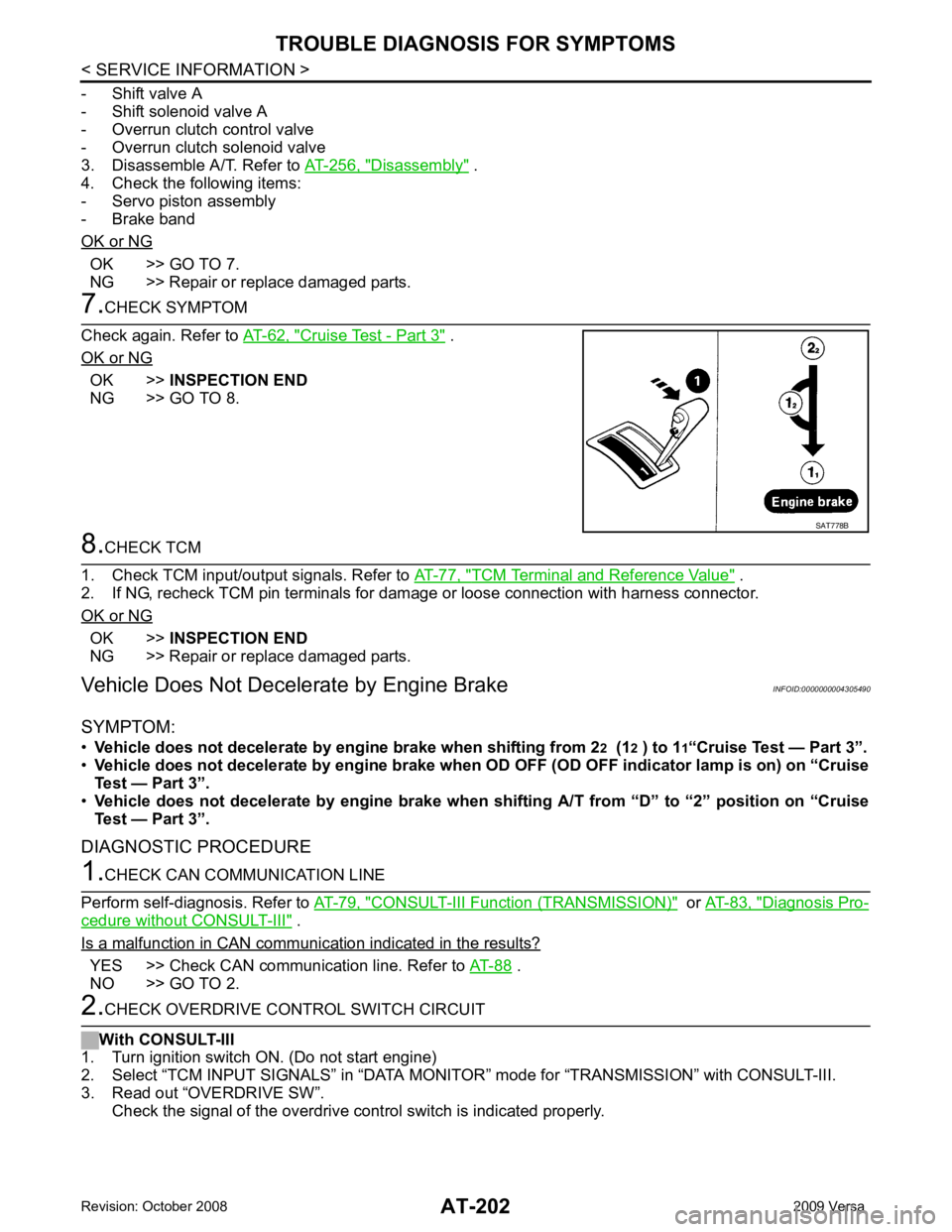
• Vehicle does not decelerate by engi ne brake when shifting from 22 (1 2 ) to 1 1“Cruise Test — Part 3”.
• Vehicle does not decelerate by engine brake when OD OFF (OD OFF indicator lamp is on) on “Cruise
Test — Part 3”.
• Vehicle does not decelerate by engi ne brake when shifting A/T from “D” to “2” position on “Cruise
Test — Part 3”.
DIAGNOSTIC PROCEDURE 1.
CHECK CAN COMMUNICATION LINE
Perform self-diagnosis. Refer to AT-79, " CONSULT-III Functi
on (TRANSMISSION) " or
AT-83, " Diagnosis Pro-
cedure without CONSULT-III " .
Is a malfunction in CAN communication indicated in the results? YES >> Check CAN communication line. Refer to
AT-88 .
NO >> GO TO 2. 2.
CHECK OVERDRIVE CONTROL SWITCH CIRCUIT
With CONSULT-III
1. Turn ignition switch ON. (Do not start engine)
2. Select “TCM INPUT SIGNALS” in “DATA MONITO R” mode for “TRANSMISSION” with CONSULT-III.
3. Read out “OVERDRIVE SW”. Check the signal of the overdrive c ontrol switch is indicated properly. SAT778B
Page 208 of 4331
TROUBLE DIAGNOSIS FOR SYMPTOMS
AT-203
< SERVICE INFORMATION >
D
E
F
G H
I
J
K L
M A
B AT
N
O P
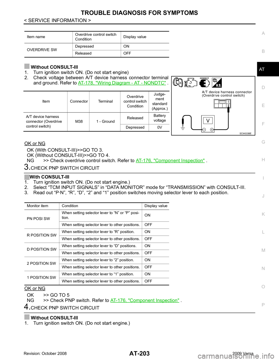
Without CONSULT-III
1. Turn ignition switch ON. (Do not start engine)
2. Check voltage between A/T device harness connector terminal and ground. Refer to AT-178, " Wiring Diagram - AT - NONDTC " .
OK or NG OK (With CONSULT-III)>>GO TO 3.
OK (Without CONSULT-III)>>GO TO 4.
NG >> Check overdrive control switch. Refer to AT-176, " Component Inspection " .
3.
CHECK PNP SWITCH CIRCUIT
With CONSULT-III
1. Turn ignition switch ON. (Do not start engine.)
2. Select “TCM INPUT SIGNALS” in “DATA MONI TOR” mode for “TRANSMISSION” with CONSULT-III.
3. Read out “P·N”, “R”, “D”, “2” and “1” position switches moving selector lever to each position.
OK or NG OK >> GO TO 5
NG >> Check PNP switch. Refer to AT-176, " Component Inspection " .
4.
CHECK PNP SWITCH CIRCUIT
Without CONSULT-III
1. Turn ignition switch ON. (Do not start engine.) Item name
Overdrive control switch
Condition Display value
OVERDRIVE SW Depressed ON
Released OFF Item Connector Terminal
Overdrive
control switch Condition Judge-
ment
standard
(Approx.)
A/T device harness
connector (Overdrive
control switch) M38 1 - Ground
Released
Battery
voltage
Depressed 0V SCIA5336E
Monitor item Condition Display value
PN POSI SW When setting selector le
ver to “N” or “P” posi-
tion. ON
When setting selector lever to other positions. OFF
R POSITION SW When setting selector lever to “R” position. ON
When setting selector lever to other positions. OFF
D POSITION SW When setting selector lever to “D” positions. ON
When setting selector lever to other positions. OFF
2 POSITION SW When setting selector lever to “2” position. ON
When setting selector lever to other positions. OFF
1 POSITION SW When setting selector lever to “1” position. ON
When setting selector lever to other positions. OFF
Page 403 of 4331
AUDIO
AV-19
< SERVICE INFORMATION >
C
D E
F
G H
I
J
L
M A
B AV
N
O P
*1: With premium system
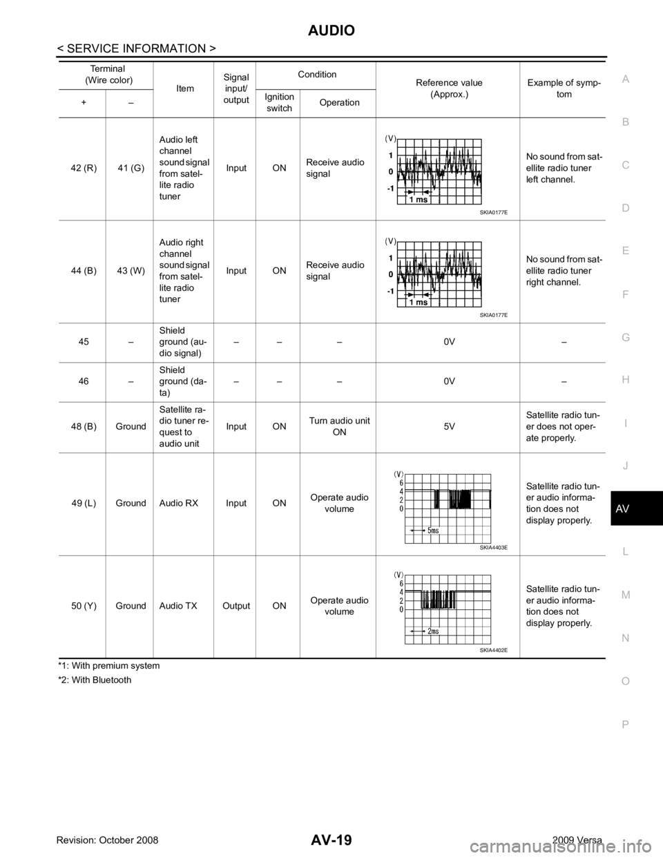
*2: With Bluetooth 42 (R) 41 (G)
Audio left
channel
sound signal
from satel-
lite radio
tuner Input ON
Receive audio
signal No sound from sat-
ellite radio tuner
left channel.
44 (B) 43 (W) Audio right
channel
sound signal
from satel-
lite radio
tuner Input ON
Receive audio
signal No sound from sat-
ellite radio tuner
right channel.
45 – Shield
ground (au-
dio signal) – – – 0V –
46 – Shield
ground (da-
ta) – – – 0V –
48 (B) Ground Satellite ra-
dio tuner re-
quest to
audio unit Input ON
Turn audio unit
ON 5VSatellite radio tun-
er does not oper-
ate properly.
49 (L) Ground Audio RX Input ON Operate audio
volume Satellite radio tun-
er audio informa-
tion does not
display properly.
50 (Y) Ground Audio TX Output ON Operate audio
volume Satellite radio tun-
er audio informa-
tion does not
display properly.
Terminal
(Wire color) ItemSignal
input/
output Condition
Reference value
(Approx.) Example of symp-
tom
+ – Ignition
switch Operation SKIA0177E
SKIA0177E
SKIA4403E
SKIA4402E
Page 406 of 4331
35, " Sound Is Not Heard from S
ubwoofer (Premium System) " .
• The majority of the audio malfunctions are the result of outside causes (damaged CD, electromagnetic inter-
ference, etc.). Check the symptom s below to diagnose the malfunction.
• The vehicle itself can be a source of noise if noise prevention parts or electrical equipment is malfunctioning.
Check if noise is caused and/or changed by engine speed, ignition switch turned to each position, and oper-
ation of each piece of electrical equipment, and then determine the cause.
NOTE:
Noise resulting from variations in field strength, such as fading noise and multi-path noise, or external noise
from trains and other sources. It is not a malfunction.
• Fading noise: This noise occurs because of variations in the field strength in a narrow range due to moun- tains or buildings blocking the signal.
• Multi-path noise: This noise results from the waves s ent directly from the broadcast station arriving at the
antenna at a different time from the waves that reflect off of mountains or buildings.
Noise Inspection INFOID:0000000004306967
The vehicle itself can be a source of noise if noise prevention parts or electrical equipment is malfunctioning.
Check if noise is caused and/or changed by engine speed, ignition switch turned to each position, and opera-
tion of each piece of electrical equipment, and determine the cause.
NOTE:
The source of the noise can be found easily by listening to the noise while removing the fuses of electrical
components, one by one.
TYPE OF NOISE AND POSSIBLE CAUSE Symptom Check item
Audio system does not work properly. • Audio unit power supply circuit. Refer to
AV-23, " Power Supply
Circuit Inspection " .
• Audio unit. Refer to "Trouble Diagnosis" .
No sound can be heard from all speakers. Audio unit. Refer to "Trouble Diagnosis" .
No sound can be heard from one or several speakers. • Open or short in audio signal circuit between audio unit and front
speaker. Refer to AV-30, " Sound Is Not Heard from Front Door
Speaker (Base System) " or
AV-32, " Sound Is Not Heard from
Front Door Speaker or Tweeter (Mid Level and Premium Sys-
tem) " .
• Front speaker. Refer to AV-30, " Sound Is Not Heard from Front
Door Speaker (Base System) " or
AV-32, " Sound Is Not Heard
from Front Door Speaker or Tweeter (Mid Level and Premium
System) " .
• Open or short in audio signal circuit between audio unit and rear
speaker. Refer to AV-31, " Sound Is Not Heard from Rear Door
Speaker (Base System) " or
AV-33, " Sound Is Not Heard from
Rear Door Speaker (Mid Level and Premium System) " .
• Rear speaker. Refer to AV-31, " Sound Is Not Heard from Rear
Door Speaker (Base System) " or
AV-33, " Sound Is Not Heard
from Rear Door Speaker (Mid Level and Premium System) " .
• Tweeter (mid level and premium system) AV-32, " Sound Is Not
Heard from Front Door Speaker or Tweeter (Mid Level and Pre-
mium System) " or
AV-33, " Sound Is Not Heard from Rear Door
Speaker (Mid Level and Premium System) " .
• Subwoofer (premium system). Refer to AV-35, " Sound Is Not
Heard from Subwoofer (Premium System) " .
• Audio unit. Refer to AV-23, " Power Supply Circuit Inspection " .
No sound can be heard from radio or noise is heard. • Antenna feeder. Refer to
AV-42 .
• Antenna. Refer to AV-42 .
• Audio unit. Refer to AV-23, " Power Supply Circuit Inspection " .