2009 NISSAN LATIO ECU
[x] Cancel search: ECUPage 3 of 4331
ACC
NP
O
ACCELERATOR CONTROL SYSTEM
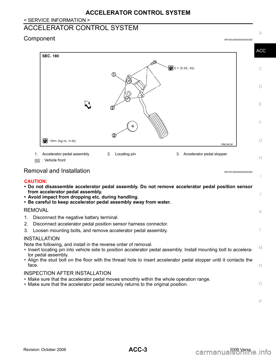
Component INFOID:0000000004305262
Removal and Installation INFOID:0000000004305263
CAUTION:
• Do not disassemble accelerator pedal assembly. Do not remove accelerator pedal position sensor
from accelerator pedal assembly.
• Avoid impact from dropping etc. during handling.
• Be careful to keep accelerator pedal assembly away from water.
REMOVAL 1. Disconnect the negative battery terminal.
2. Disconnect accelerator pedal position sensor harness connector.
3. Loosen mounting bolts, and remove accelerator pedal assembly.
INSTALLATION Note the following, and install in the reverse order of removal.
• Insert locating pin into vehicle side to position accelerator pedal assembly. Install mounting bolt to accelera- tor pedal assembly.
• Align the stud bolt on the floor with the thread hole to in sert accelerator pedal stopper until it contacts the
face.
INSPECTION AFTER INSTALLATION • Make sure that the accelerator pedal mo ves smoothly within the whole operation range.
• Make sure that the accelerator pedal securely returns to the original position. 1. Accelerator pedal assembly 2. Locating pin 3. Accelerator pedal stopper
: Vehicle front
Page 84 of 4331

AT
N
O P
*1
: These terminals are connected to the data link connector.
*2 : These terminals are connected to the ECM.
CONSULT-III Function (TRANSMISSION) INFOID:0000000004305330
CONSULT-III can display each diagnostic item using the diagnostic test models shown following.
FUNCTION
CONSULT-III REFERENCE VALUE NOTICE:
1. The CONSULT-III electrically displays shift timi ng and lock-up timing (that is, operation timing of each
solenoid).
Check for time difference between actual shift timi ng and the CONSULT-III display. If the difference is
noticeable, mechanical parts (except solenoids, sens ors, etc.) may be malfunctioning. Check mechanical
parts using applicable diagnostic procedures.
2. Shift schedule (which implies gear position) display ed on CONSULT-III and that indicated in Service Man-
ual may differ slightly. This occurs because of the following reasons:
- Actual shift schedule has more or less tolerance or allowance,
- Shift schedule indicated in Service Manual re fers to the point where shifts start, and
- Gear position displayed on CONSULT-III indicates the point where shifts are completed.
3. Shift solenoid valve “A” or “B” is displayed on CONSUL T-III at the start of shifting. Gear position is dis-
played upon completion of shifting (which is computed by TCM).
39
*2
L Engine speed signal
and Refer to
EC-461 (HR16DE),
EC-597 (MR Type 1) or
EC- 1109 (MR Type 2).
40 O Vehicle speed sensor When driving vehicle at 2 to 3 km/h (1 to
2 MPH) for 1 m (3 ft) or more. Voltage varies
between less
than 0 V and
more than 4.5 V
42 B Sensor ground Always 0 V
47 BR A/T fluid temperature
sensor and When A/T fluid temperature is 20
°C
(68 °F). 1.5 V
When A/T fluid temperature is 80 °C
(176 °F). 0.5 V
48 B Ground Always 0 V
Terminal
Wire
color Item Condition Judgement stan-
dard (Approx.) Diagnostic test mode Function
Work Support This mode enables a technician to adjust some devices faster and more accuratelyI.
Self Diagnostic Results Retrieve DTC from ECU and display diagnostic items.
Data Monitor Monitor the input/output signal of the control unit in real time.
CAN Diagnosis Support Monitor It monitors the status of CAN communication.
Function Test This mode can show results of self-diagnosis of ECU with either “OK” or “NG”. For engine, more
practical tests regarding sensors/switches and/or actuators are available.
DTC & SRT confirmation The status of system monitoring tests and the self-diagnosis status/result can be confirmed.
ECU Identification Display the ECU identification number (part number etc.) of the selected system. Item name Condition Display value (Approx.)
VHCL/S SE-A/T During driving Approximately matches the speedometer
reading.
VHCL/S SE-MTR
THROTTLE POSI Released accelerator pedal. 0.0/8
Fully depressed accelerator pedal. 8.0/8
Page 96 of 4331
AT
N
O P
DTC P0705 PARK/NEUTRAL POSITION (PNP) SWITCH
Description INFOID:0000000004305338
• The PNP switch assembly includes a transaxle range switch.
• The transaxle range switch detects the selector lever position and sends a signal to the TCM.
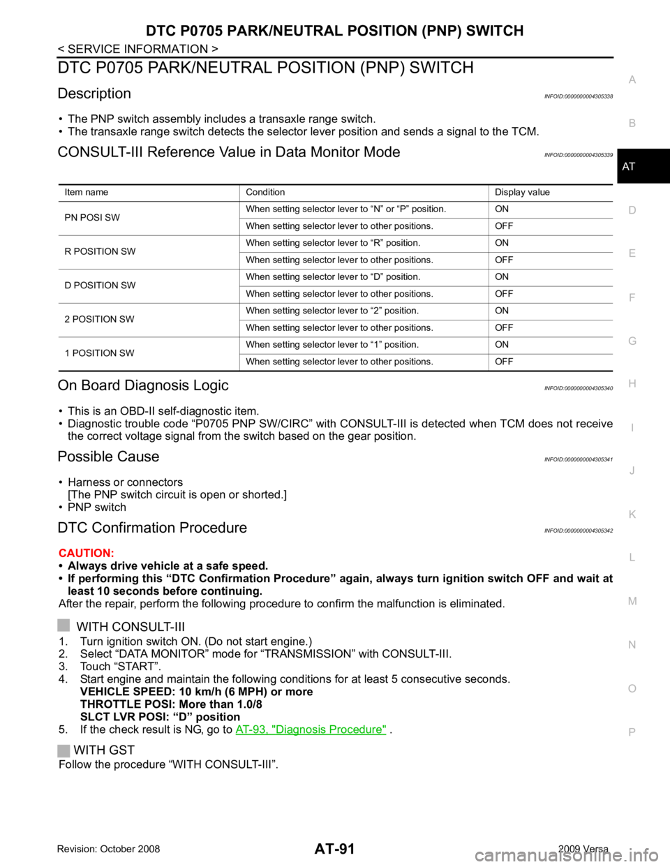
CONSULT-III Reference Val ue in Data Monitor Mode INFOID:0000000004305339
On Board Diagnosis Logic INFOID:0000000004305340
• This is an OBD-II self-diagnostic item.
• Diagnostic trouble code “P0705 PNP SW/CIRC” with CONS ULT-III is detected when TCM does not receive
the correct voltage signal from the switch based on the gear position.
Possible Cause INFOID:0000000004305341
• Harness or connectors [The PNP switch circuit is open or shorted.]
• PNP switch
DTC Confirmation Procedure INFOID:0000000004305342
CAUTION:
• Always drive vehicle at a safe speed.
• If performing this “DTC Confirmation Procedure” again, always turn ignition switch OFF and wait at
least 10 seconds before continuing.
After the repair, perform the following procedure to confirm the malfunction is eliminated.
WITH CONSULT-III
1. Turn ignition switch ON. (Do not start engine.)
2. Select “DATA MONITOR” mode for “TRANSMISSION” with CONSULT-III.
3. Touch “START”.
4. Start engine and maintain the following conditions for at least 5 consecutive seconds.
VEHICLE SPEED: 10 km/h (6 MPH) or more
THROTTLE POSI: More than 1.0/8
SLCT LVR POSI: “D” position
5. If the check result is NG, go to AT-93, " Diagnosis Procedure " .
WITH GST
Follow the procedure “WITH CONSULT-III”. Item name Condition Display value
PN POSI SW When setting selector lever
to “N” or “P” position. ON
When setting selector lever to other positions. OFF
R POSITION SW When setting selector lever to “R” position. ON
When setting selector lever to other positions. OFF
D POSITION SW When setting selector lever to “D” position. ON
When setting selector lever to other positions. OFF
2 POSITION SW When setting selector lever to “2” position. ON
When setting selector lever to other positions. OFF
1 POSITION SW When setting selector lever to “1” position. ON
When setting selector lever to other positions. OFF
Page 106 of 4331
AT
N
O P
DTC P0720 VEHICLE SPEED SENS
OR A/T (REVOLUTION SENSOR)
Description INFOID:0000000004305354
The revolution sensor detects the revolution of the id ler gear parking pawl lock gear and emits a pulse signal.
The pulse signal is sent to the TCM which converts it into vehicle speed.
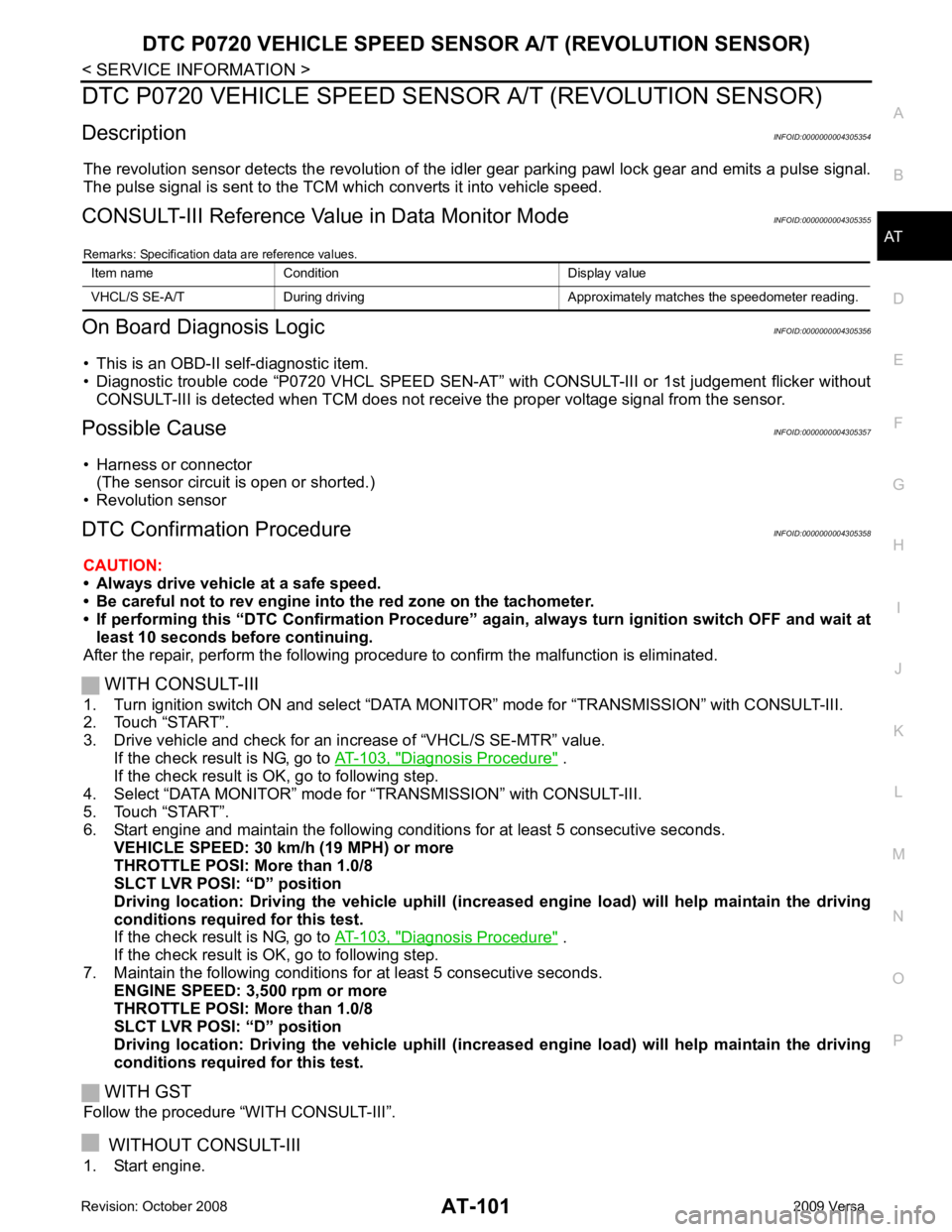
CONSULT-III Reference Val ue in Data Monitor Mode INFOID:0000000004305355
Remarks: Specification data are reference values.
On Board Diagnosis Logic INFOID:0000000004305356
• This is an OBD-II self-diagnostic item.
• Diagnostic trouble code “P0720 VHCL SPEED SEN-AT” with CONSULT-III or 1st judgement flicker without
CONSULT-III is detected when TCM does not rece ive the proper voltage signal from the sensor.
Possible Cause INFOID:0000000004305357
• Harness or connector (The sensor circuit is open or shorted.)
• Revolution sensor
DTC Confirmation Procedure INFOID:0000000004305358
CAUTION:
• Always drive vehicle at a safe speed.
• Be careful not to rev engine into the red zone on the tachometer.
• If performing this “DTC Confirmation Procedure” again, always turn ignition switch OFF and wait at
least 10 seconds before continuing.
After the repair, perform the following procedure to confirm the malfunction is eliminated.
WITH CONSULT-III
1. Turn ignition switch ON and select “DATA MO NITOR” mode for “TRANSMISSION” with CONSULT-III.
2. Touch “START”.
3. Drive vehicle and check for an in crease of “VHCL/S SE-MTR” value.
If the check result is NG, go to AT-103, " Diagnosis Procedure " .
If the check result is OK, go to following step.
4. Select “DATA MONITOR” mode for “TRANSMISSION” with CONSULT-III.
5. Touch “START”.
6. Start engine and maintain the following conditions for at least 5 consecutive seconds. VEHICLE SPEED: 30 km/h (19 MPH) or more
THROTTLE POSI: More than 1.0/8
SLCT LVR POSI: “D” position
Driving location: Driving the vehic le uphill (increased engine load) will help maintain the driving
conditions required for this test.
If the check result is NG, go to AT-103, " Diagnosis Procedure " .
If the check result is OK, go to following step.
7. Maintain the following conditions for at least 5 consecutive seconds. ENGINE SPEED: 3,500 rpm or more
THROTTLE POSI: More than 1.0/8
SLCT LVR POSI: “D” position
Driving location: Driving the vehic le uphill (increased engine load) will help maintain the driving
conditions required for this test.
WITH GST
Follow the procedure “WITH CONSULT-III”.
WITHOUT CONSULT-III
1. Start engine. Item name Condition Display value
VHCL/S SE-A/T During driving Approxima tely matches the speedometer reading.
Page 221 of 4331
.
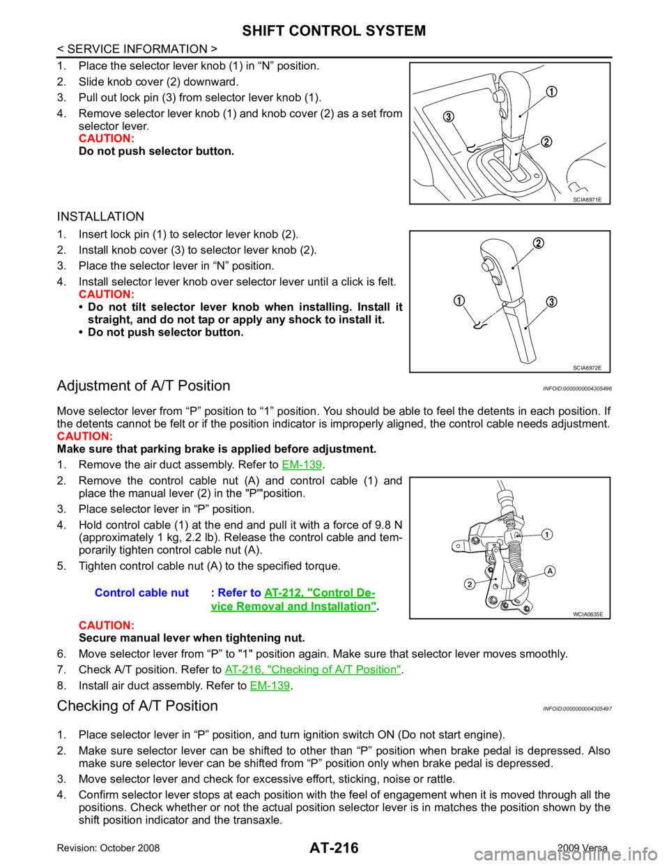
2. Remove the control cable nut (A) and control cable (1) and place the manual lever (2) in the "P'"position.
3. Place selector lever in “P” position.
4. Hold control cable (1) at the end and pull it with a force of 9.8 N (approximately 1 kg, 2.2 lb). Release the control cable and tem-
porarily tighten control cable nut (A).
5. Tighten control cable nut (A) to the specified torque.
CAUTION:
Secure manual lever when tightening nut.
6. Move selector lever from “P” to "1" position again. Make sure that selector lever moves smoothly.
7. Check A/T position. Refer to AT-216, " Checking of A/T Position " .
8. Install air duct assembly. Refer to EM-139 .
Checking of A/T Position INFOID:0000000004305497
1. Place selector lever in “P” position, and tu rn ignition switch ON (Do not start engine).
2. Make sure selector lever can be shifted to other than “P” position when brake pedal is depressed. Also
make sure selector lever can be shifted from “P” position only when brake pedal is depressed.
3. Move selector lever and check for excessive effort, sticking, noise or rattle.
4. Confirm selector lever stops at each position with the feel of engagement when it is moved through all the
positions. Check whether or not the actual position sele ctor lever is in matches the position shown by the
shift position indicator and the transaxle. SCIA6972E
Control De-
vice Removal and Installation " .
Page 224 of 4331

AT
N
O P
7. Remove steering column cover (upper and lower) and instru-
ment lower finisher. Refer to IP-11 .
8. Pull out the lock plate (A) from the holder (B).
9. Remove the key interlock cable (1) from the key cylinder (2).
10. Remove the clip (A), and then remove the key interlock cable (1).
INSTALLATION CAUTION:
• Install key interlock cable in such a way that it will not be damaged by sharp bends, twists or interfer-
ence with adjacent parts.
• After installing key interlock cable to contro l device assembly, make sure that casing cap and
bracket are firmly secured in their positions.
1. Place the selector lever in the “P” position.
2. Turn ignition switch to “ACC” or “ON” position.
3. Set the key interlock cable (1) to the key cylinder (2).
4. Install the lock plate (A) to the holder (B).
5. Turn ignition switch to “LOCK” position.
6. Temporarily install the adjust holder (A) to the key interlock rod (B).
7. Install the casing cap (C) to the cable bracket (D) on the control device assembly.
CAUTION:
• Do not bend or twist key interlock cable excessively when
installing.
• After installing key interlo ck cable to cable bracket (D) on
control device assembly, make sure casing cap (C) is
firmly secured in cable bracket (D) on control device
assembly.
• If casing cap (C) is loose [less than 39.2 N (4.0 kg, 8.8 lb)
removing force], replace key interlock cable.
Page 232 of 4331
AT
N
O P
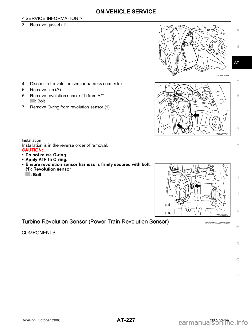
3. Remove gusset (1).
4. Disconnect revolution sensor harness connector.
5. Remove clip (A).
6. Remove revolution sensor (1) from A/T. : Bolt
7. Remove O-ring from revolution sensor (1)
Installation Installation is in the reverse order of removal.
CAUTION:
• Do not reuse O-ring.
• Apply ATF to O-ring.
• Ensure revolution sensor harn ess is firmly secured with bolt.
(1): Revolution sensor
: Bolt
Turbine Revolution Sensor (Power Train Revolution Sensor) INFOID:0000000004305506
COMPONENTS
Page 238 of 4331
AT
N
O P
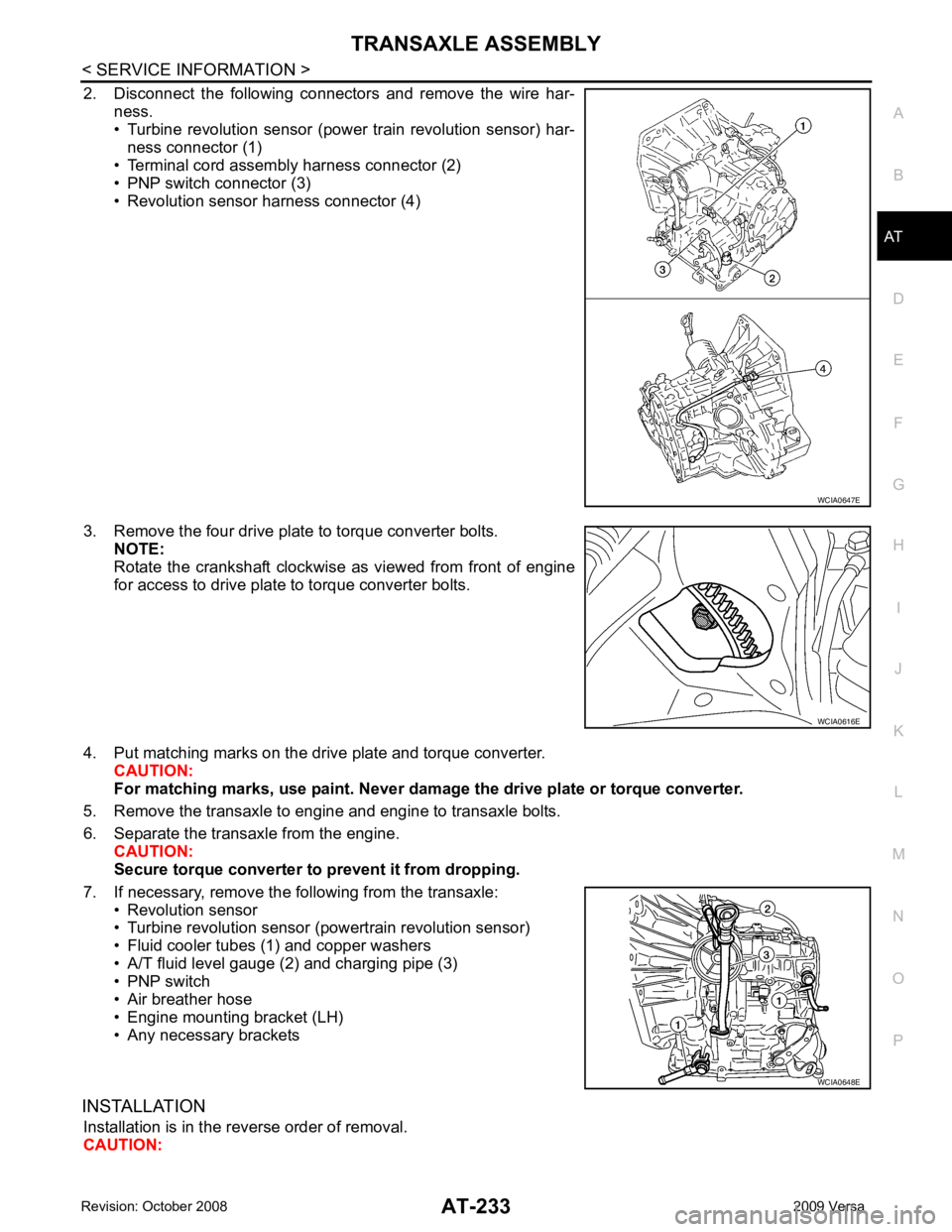
2. Disconnect the following connectors and remove the wire har-
ness.
• Turbine revolution sensor (power train revolution sensor) har-
ness connector (1)
• Terminal cord assembly harness connector (2)
• PNP switch connector (3)
• Revolution sensor harness connector (4)
3. Remove the four drive plate to torque converter bolts. NOTE:
Rotate the crankshaft clockwise as viewed from front of engine
for access to drive plate to torque converter bolts.
4. Put matching marks on the drive plate and torque converter. CAUTION:
For matching marks, use paint. Never dama ge the drive plate or torque converter.
5. Remove the transaxle to engine and engine to transaxle bolts.
6. Separate the transaxle from the engine. CAUTION:
Secure torque converter to prevent it from dropping.
7. If necessary, remove the following from the transaxle: • Revolution sensor
• Turbine revolution sensor (powertrain revolution sensor)
• Fluid cooler tubes (1) and copper washers
• A/T fluid level gauge (2) and charging pipe (3)
• PNP switch
• Air breather hose
• Engine mounting bracket (LH)
• Any necessary brackets
INSTALLATION Installation is in the reverse order of removal.
CAUTION: WCIA0616E
WCIA0648E