2009 NISSAN LATIO ECU
[x] Cancel search: ECUPage 239 of 4331
.
• After converter is installed to drive plate, ro tate crankshaft several turns to check that transaxle
rotates freely without binding.
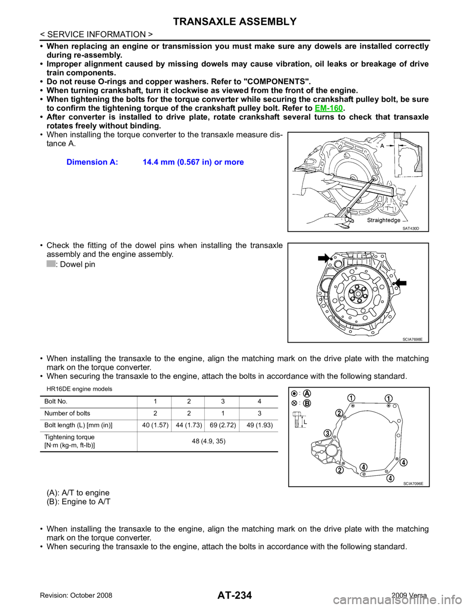
• When installing the torque converter to the transaxle measure dis- tance A.
• Check the fitting of the dowel pins when installing the transaxle
assembly and the engine assembly.
: Dowel pin
• When installing the transaxle to the engine, align t he matching mark on the drive plate with the matching
mark on the torque converter.
• When securing the transaxle to the engine, attach the bolts in accordance with the following standard.
HR16DE engine models
(A): A/T to engine
(B): Engine to A/T
• When installing the transaxle to the engine, align t he matching mark on the drive plate with the matching
mark on the torque converter.
• When securing the transaxle to the engine, attach the bolts in accordance with the following standard.
Dimension A: 14.4 mm (0.567 in) or more
SCIA7698E
Page 375 of 4331
AT-370< SERVICE INFORMATION >
ASSEMBLY
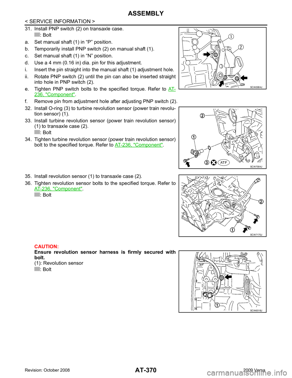
31. Install PNP switch (2) on transaxle case. : Bolt
a. Set manual shaft (1) in “P” position.
b. Temporarily install PNP switch (2) on manual shaft (1).
c. Set manual shaft (1) in “N” position.
d. Use a 4 mm (0.16 in) dia. pin for this adjustment.
i. Insert the pin straight into the manual shaft (1) adjustment hole.
ii. Rotate PNP switch (2) until the pin can also be inserted straight into hole in PNP switch (2).
e. Tighten PNP switch bolts to the specified torque. Refer to AT-236, " Component " .
f. Remove pin from adjustment hole after adjusting PNP switch (2).
32. Install O-ring (3) to turbine revolution sensor (power train revolu- tion sensor) (1).
33. Install turbine revolution sensor (power train revolution sensor) (1) to transaxle case (2).
: Bolt
34. Tighten turbine revolution sensor (power train revolution sensor) bolt to the specified torque. Refer to AT-236, " Component " .
35. Install revolution sensor (1) to transaxle case (2).
36. Tighten revolution sensor bolts to the specified torque. Refer to AT-236, " Component " .
: Bolt
CAUTION:
Ensure revolution sensor harness is firmly secured with
bolt.
(1): Revolution sensor
: Bolt SCIA5904J
SCIA7004J
SCIA7170J
SCIA6518J
Page 448 of 4331

System Description " .
• Remote keyless entry system. Refer to BL-58, " System Description " .
• Power window system (with power windows). Refer to GW-19, " System Description " .
NOTE
• Sunroof system (with sunroof). Refer to RF-11, " System Description " .
NOTE
• Room lamp timer. Refer to LT-91, " System Description " .
• Rear wiper and washer system (Hatchback). Refer to WW-25, " System Description " .
NOTE:
Power supply only. No system control.
SYSTEMS CONTROLLED BY BCM AND IPDM E/R
• Panic system. Refer to BL-58, " System Description " .
• Vehicle security (theft warning) system. Refer to BL-219, " System Description " .
• NVIS(NATS) system. Refer to BL-248, " System Description " .
• Headlamp, tail lamp and battery saver control systems. Refer to LT-73, " System Description " ,
LT-4, " System
Description " or
LT-25, " System Description " .
• Front fog lamp (with front fog lamps). Refer to LT-39, " System Description " .
• Front wiper and washer system. Refer to WW-3, " System Description " .
• Rear window defogger system. Refer to GW-51, " System Description " .
SYSTEMS CONTROLLED BY BCM AND COMBINATION METER
• Warning chime. Refer to DI-42, " System Description " .
• Turn signal and hazard warning lamps. Refer to LT-48, " System Description " .
SYSTEMS CONTROLLED BY BCM AND INTELLIGENT KEY UNIT (WITH INTELLIGENT KEY)
• Intelligent Key system. Refer to BL-88, " System Description " .
MAJOR COMPONENTS AND CONTROL SYSTEM
System Input Output
Remote keyless entry system (with
power door locks) Remote keyless entry receiver
(keyfob) • All door locking actuators
• Turn signal lamp (LH, RH)
• Combination meter (turn signal lamp)
Intelligent Key system (with Intelligent
Key) Intelligent Key unit• All door locking actuators
• Turn signal lamp (LH, RH)
• Combination meter (turn signal lamp)
Power door lock system (with power
door locks) Front power door lock/unlock
switch (LH, RH) All door locking actuators
Power supply (IGN/RAP) to power
window (with power windows) Ignition retained power supply Power supply to power window and sunroof system
Power supply (BAT) to power window
(with power windows) Battery power supply Power supply to power window and sunroof system
Page 449 of 4331
BCS
N
O P
CAN Communication System Description INFOID:0000000004306834
Refer to LAN-8, " System Description " .
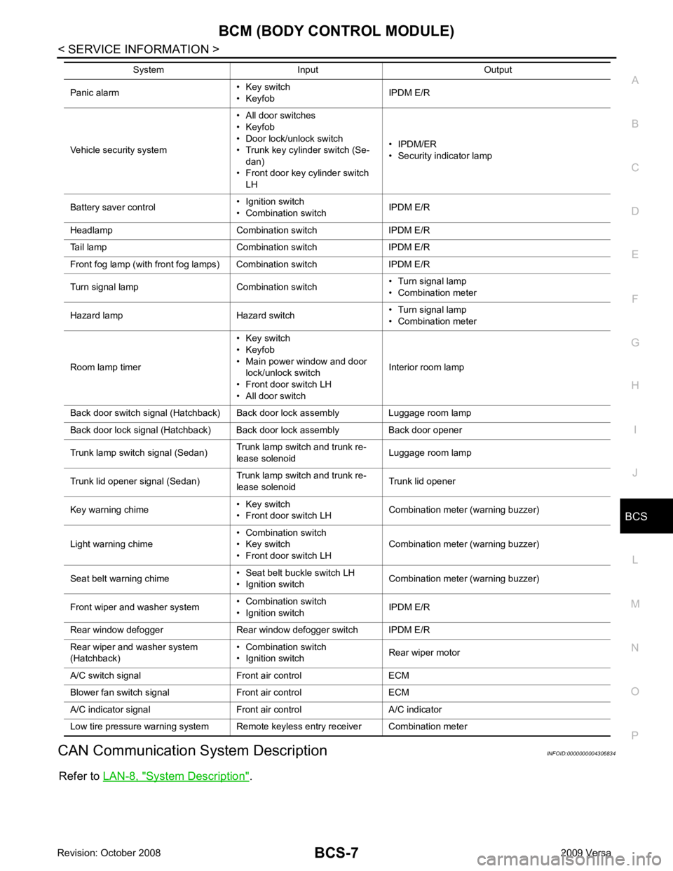
Panic alarm
• Key switch
• Keyfob IPDM E/R
Vehicle security system • All door switches
• Keyfob
• Door lock/unlock switch
• Trunk key cylinder switch (Se-
dan)
• Front door key cylinder switch LH • IPDM/ER
• Security indicator lamp
Battery saver control • Ignition switch
• Combination switch IPDM E/R
Headlamp Combination switch IPDM E/R
Tail lamp Combination switch IPDM E/R
Front fog lamp (with front fog lamps) Combination switch IPDM E/R
Turn signal lamp Combination switch • Turn signal lamp
• Combination meter
Hazard lamp Hazard switch • Turn signal lamp
• Combination meter
Room lamp timer • Key switch
• Keyfob
• Main power window and door lock/unlock switch
• Front door switch LH
• All door switch Interior room lamp
Back door switch signal (Hatchback) Back door lock assembly Luggage room lamp
Back door lock signal (Hatchback) Back door lock assembly Back door opener
Trunk lamp switch signal (Sedan) Trunk lamp switch and trunk re-
lease solenoid Luggage room lamp
Trunk lid opener signal (Sedan) Trunk lamp switch and trunk re-
lease solenoid Trunk lid opener
Key warning chime • Key switch
• Front door switch LH Combination meter (warning buzzer)
Light warning chime • Combination switch
• Key switch
• Front door switch LH Combination meter (warning buzzer)
Seat belt warning chime • Seat belt buckle switch LH
• Ignition switch Combination meter (warning buzzer)
Front wiper and washer system • Combination switch
• Ignition switch IPDM E/R
Rear window defogger Rear window defogger switch IPDM E/R
Rear wiper and washer system
(Hatchback) • Combination switch
• Ignition switch Rear wiper motor
A/C switch signal Front air control ECM
Blower fan switch signal Front air control ECM
A/C indicator signal Front air control A/C indicator
Low tire pressure warning system Remote keyless entry receiver Combination meter System Input Output
Page 458 of 4331
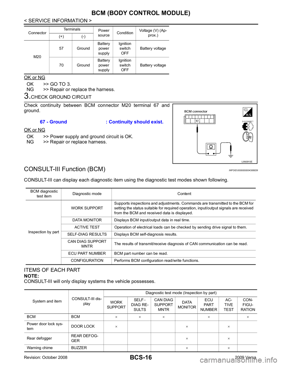
OK >> GO TO 3.
NG >> Repair or replace the harness. OK >> Power supply and ground circuit is OK.
NG >> Repair or replace harness.
CONSULT-III Function (BCM) INFOID:0000000004306839
CONSULT-III can display each diagnostic item us ing the diagnostic test modes shown following.
ITEMS OF EACH PART
NOTE:
CONSULT-III will only display systems the vehicle possesses. M20
57 Ground
Battery
power
supply Ignition
switch
OFF Battery voltage
70 Ground Battery
power
supply Ignition
switch OFF Battery voltage
Connector
Terminals
Power
source Condition Voltage (V) (Ap-
prox.)
(+) (-) System and item
CONSULT-III dis-
play Diagnostic test mode (Inspection by part)
WORK
SUPPORT SELF
−
DIAG RE- SULTS CAN DIAG
SUPPORT MNTR DATA
MONITOR ECU
PART
NUMBER AC-
TIVE
TEST CON-
FIGU-
RATION
BCM BCM × × × × ×
Power door lock sys-
tem DOOR LOCK
× × ×
Rear defogger REAR DEFOG-
GER × ×
Warning chime BUZZER × ×
Page 462 of 4331

BL
N
O P
CONTENTS
BODY, LOCK & SECURITY SYSTEM
SERVICE INFORMATION .. ..........................4
PRECAUTIONS .............................................. .....4
Precaution for Supplemental Restraint System
(SRS) "AIR BAG" and "SEAT BELT PRE-TEN-
SIONER" ............................................................. ......
4
Precaution Necessary fo r Steering Wheel Rota-
tion After Battery Disconnect ............................... ......
4
Precaution for Procedure without Cowl Top Cover ......5
Precaution for Work ............................................ ......5
PREPARATION .............................................. .....6
Special Service Tool ........................................... ......6
Commercial Service Tool .................................... ......6
SQUEAK AND RATTLE TROUBLE DIAG-
NOSES ........................ ........................................7
Work Flow ........................................................... ......7
Generic Squeak and Rattle Troubleshooting ...... ......9
Diagnostic Worksheet ......................................... ....11
HOOD ............................................................. ....13
Fitting Adjustment ............................................... ....13
Removal and Installation .........................................14
Removal and Installation of Hood Lock Control .. ....15
Hood Lock Control Inspec tion .................................17
RADIATOR CORE SUPPORT ....................... ....19
Removal and Installation .........................................19
FRONT FENDER ............................................ ....21
Removal and Installation .........................................21
POWER DOOR LOCK SYSTEM .................... ....22
Component Parts and Harness Connector Loca-
tion ...................................................................... ....
22
System Description ............................................. ....23
CAN Communication System Description ........... ....25
Schematic ........................................................... ....26
Wiring Diagram - D/LOCK - ................................. ....27
Schematic ........................................................... ....31
Wiring Diagram - D/LOCK - ................................. ....32 Terminal and Reference
Value for BCM ..................37
Work Flow ............................................................ ....41
CONSULT-III Function (B CM) .................................41
Trouble Diagnosis Symptom Chart ...................... ....43
BCM Power Supply and Ground Circuit Inspection ....43
Door Switch Check (Hatchback) .......................... ....44
Door Switch Check (Sedan) ................................ ....47
Key Switch (Insert) Check ................................... ....48
Door Lock and Unlock Switch Check .................. ....49
Front Door Lock Assembly LH (Actuator) Check .....52
Door Lock Actuator Check (Front RH and Rear
LH/RH) ................................................................. ....
53
Front Door Key Cylinder S witch LH Check ..............54
Passenger Select Unlock Relay Circuit Inspection
(With Intelligent Key) ........................................... ....
55
REMOTE KEYLESS ENTRY SYSTEM ............. 58
Component Parts and Harness Connector Loca-
tion ....................................................................... ....
58
System Description .............................................. ....58
CAN Communication System Description ........... ....60
Schematic ............................................................ ....61
Wiring Diagram - KEYLES - ................................ ....62
Terminal and Reference Value for BCM ..................65
How to Perform Trouble Diagnosis ...................... ....69
Preliminary Check ............................................... ....69
CONSULT-III Function (B CM) .................................69
Work Flow ............................................................ ....71
Trouble Diagnosis Symptom Chart ...................... ....71
Keyfob Battery and Function Check .................... ....72
ACC Switch Check .............................................. ....74
Door Switch Check (Hatchback) .......................... ....74
Door Switch Check (Sedan) ................................ ....76
Key Switch (Insert) Check ................................... ....78
Hazard Function Check ....................................... ....78
Horn Function Check ........................................... ....79
Interior Lamp and Ignition Keyhole Illumination
Function Check .................................................... ....
79
Remote Keyless Entry Rece iver Check ...................80
Keyfob Function (Lock) Check ............................ ....82
Page 464 of 4331

BL
N
O P
Check Trunk Lid Opener S
witch Circuit (With Intel-
ligent Key) ........................................................... ..
212
Check Trunk Release Solenoid Circuit ............... ..214
FUEL FILLER LID OPENER .......................... ..217
Removal and Installation of Fuel Filler Lid Opener ..217
VEHICLE SECURITY (THEFT WARNING)
SYSTEM ......................................................... ..
218
Component Parts and Harness Connector Loca-
tion ...................................................................... ..
218
System Description ............................................. ..219
CAN Communication System Description ........... ..221
Schematic ........................................................... ..222
Wiring Diagram - VEHSEC - ............................... ..223
Terminal and Reference Value for BCM ............. ..227
Terminal and Re ference Value for Intelligent Key
Unit ...................................................................... ..
231
CONSULT-III Function (BCM) ............................. ..233
Trouble Diagnosis ............................................... ..235
Preliminary Check ............................................... ..235
Symptom Chart ................................................... ..237
Diagnosis Procedure 1 ........................................ ..238
Diagnosis Procedure 2 ........................................ ..241
Diagnosis Procedure 3 ........................................ ..242
Diagnosis Procedure 4 ........................................ ..242
Diagnosis Procedure 5 ........................................ ..242
Diagnosis Procedure 6 ........................................ ..242
Diagnosis Procedure 7 ........................................ ..242
Diagnosis Procedure 8 ........................................ ..244
Diagnosis Procedure 9 ........................................ ..245 NATS (Nissan Anti-Theft System) ................
248
Component Parts and Harness Connector Loca-
tion ....................................................................... ..
248
System Description .............................................. ..248
System Composition ............................................ ..249
ECM Re-communicating Function ....................... ..249
Wiring Diagram - NATS - ..................................... ..251
Terminal and Reference Value for BCM ................252
CONSULT-III Function ........................................ ..256
Trouble Diagnosis Procedure .............................. ..257
Trouble Diagnosis ................................................ ..259
Diagnosis Procedure 1 ........................................ ..260
Diagnosis Procedure 2 ........................................ ..262
Diagnosis Procedure 3 ........................................ ..263
Diagnosis Procedure 4 ........................................ ..264
Diagnosis Procedure 5 ........................................ ..265
Diagnosis Procedure 6 ........................................ ..266
How to Replace NATS Antenna Amp .................. ..266
BODY REPAIR ................................................ 267
Body Exterior Paint Color .................................... ..267
Body Component Parts ....................................... ..269
Corrosion Protection ............................................ ..274
Body Sealing ....................................................... ..278
Body Construction ............................................... ..284
Body Alignment ................................................... ..286
Handling Precaution for Plastics .......................... ..303
Precaution in Repairing High Strength Steel ....... ..307
Foam Repair ........................................................ ..310
Replacement Operation ....................................... ..313
Page 469 of 4331
Generic Squeak and Rattle Troubleshooting " .
REPAIR THE CAUSE
• If the cause is a loose component, tighten the component securely.
• If the cause is insufficient clearance between components:
- separate components by repositioning or loos ening and retightening the component, if possible.
- insulate components with a suitable insulator such as urethane pads, foam blocks, felt cloth tape or urethane
tape. A NISSAN Squeak and Rattle Kit (J-43980) is av ailable through your authorized NISSAN Parts Depart-
ment.
CAUTION:
Do not use excessive force as many components are constructed of plastic and may be damaged.
Always check with the Parts Department for the latest parts information.
The following materials are contained in the NISS AN Squeak and Rattle Kit (J-43980). Each item can be
ordered separately as needed.
URETHANE PADS [1.5 mm (0.059 in) thick]
Insulates connectors, harness, etc.
76268-9E005: 100 ×135 mm (3.94 ×5.31 in)/76884-71L01: 60 ×85 mm (2.36 ×3.35 in)/76884-71L02: 15 ×25
mm (0.59 ×0.98 in)
INSULATOR (Foam blocks)
Insulates components from contact. Can be used to fill space behind a panel.
73982-9E000: 45 mm (1.77 in) thick, 50 ×50 mm (1.97 ×1.97 in)/73982-50Y00: 10 mm (0.39 in) thick,
50 ×50 mm (1.97 ×1.97 in)
INSULATOR (Light foam block)
80845-71L00: 30 mm (1.18 in) thick, 30 ×50 mm (1.18 ×1.97 in)
FELT CLOTH TAPE
Used to insulate where movemen t does not occur. Ideal for instrument panel applications.
68370-4B000: 15 ×25 mm (0.59 ×0.98 in) pad/68239-13E00: 5 mm (0.20 in ) wide tape roll. The following
materials not found in the kit can also be used to repair squeaks and rattles.
UHMW (TEFLON) TAPE
Insulates where slight movemen t is present. Ideal for instrument panel applications.