2009 NISSAN LATIO ECU
[x] Cancel search: ECUPage 478 of 4331
HOOD
BL-17
< SERVICE INFORMATION >
C
D E
F
G H
J
K L
M A
B BL
N
O P
Be careful not to bend the cable too much, keeping the
radius 100 mm (3.94 in) or more.
2. Check that the cable is not of fset from the positioning grommet,
and push the grommet into the panel hole securely.
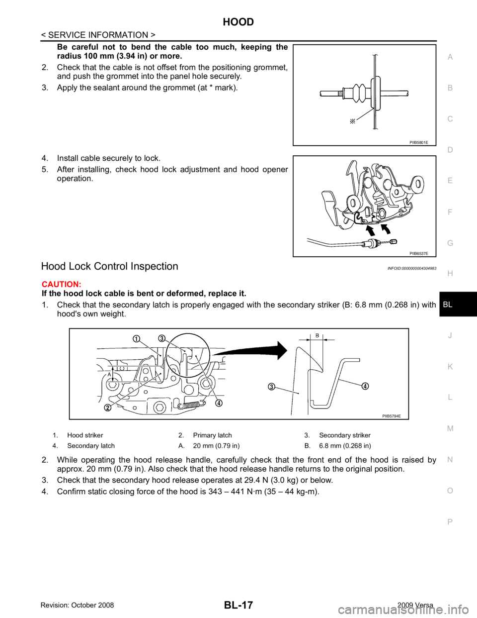
3. Apply the sealant around the grommet (at * mark).
4. Install cable securely to lock.
5. After installing, check hood lock adjustment and hood opener operation.
Hood Lock Control Inspection INFOID:0000000004304983
CAUTION:
If the hood lock cable is bent or deformed, replace it.
1. Check that the secondary latch is properly engaged with the secondary striker (B: 6.8 mm (0.268 in) with
hood's own weight.
2. While operating the hood release handle, carefully check that the front end of the hood is raised by
approx. 20 mm (0.79 in). Also check that the hood release handle returns to the original position.
3. Check that the secondary hood release operates at 29.4 N (3.0 kg) or below.
4. Confirm static closing force of the hood is 343 – 441 N·m (35 – 44 kg-m). PIIB5801E
PIIB6537E
1. Hood striker 2. Primary
latch 3. Secondary striker
4. Secondary latch A. 20 mm (0.79 in) B. 6.8 mm (0.268 in) PIIB5794E
Page 499 of 4331
BL-38< SERVICE INFORMATION >
POWER DOOR LOCK SYSTEM
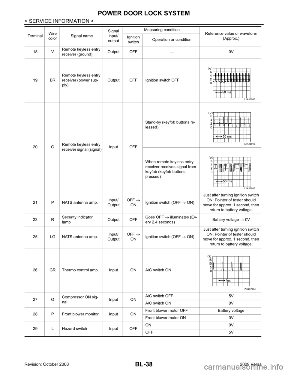
18 V Remote keyless entry
receiver (ground) Output OFF — 0V
19 BR Remote keyless entry
receiver (power sup-
ply) Output OFF Ignition switch OFF
20 G Remote keyless entry
receiver signal (signal) Input OFFStand-by (keyfob buttons re-
leased)
When remote keyless entry
receiver receives signal from
keyfob (keyfob buttons
pressed)
21 P NATS antenna amp. Input/
Output OFF
→
ON Ignition switch (OFF
→ ON) Just after turning ignition switch
ON: Pointer of tester should
move for approx. 1 second, then return to battery voltage.
23 R Security indicator
lamp Output OFFGoes OFF
→ illuminates (Ev-
ery 2.4 seconds) Battery voltage
→ 0V
25 LG NATS antenna amp. Input/
Output OFF
→
ON Ignition switch (OFF
→ ON) Just after turning ignition switch
ON: Pointer of tester should
move for approx. 1 second, then
return to battery voltage.
26 GR Thermo control amp. Input ON A/C switch ON
27 O Compressor ON sig-
nal Input ONA/C switch OFF 5V
A/C switch ON 0V
28 P Front blower monitor Input ON Front blower motor OFF Battery voltage
Front blower motor ON 0V
29 L Hazard switch Input OFF ON 0V
OFF 5V
Terminal
Wire
color Signal name Signal
input/
output Measuring condition
Reference value or waveform
(Approx.)
Ignition
switch Operation or condition LIIA1893E
LIIA1894E
LIIA1895E
ZJIA0719J
Page 527 of 4331
BL-66< SERVICE INFORMATION >
REMOTE KEYLESS ENTRY SYSTEM
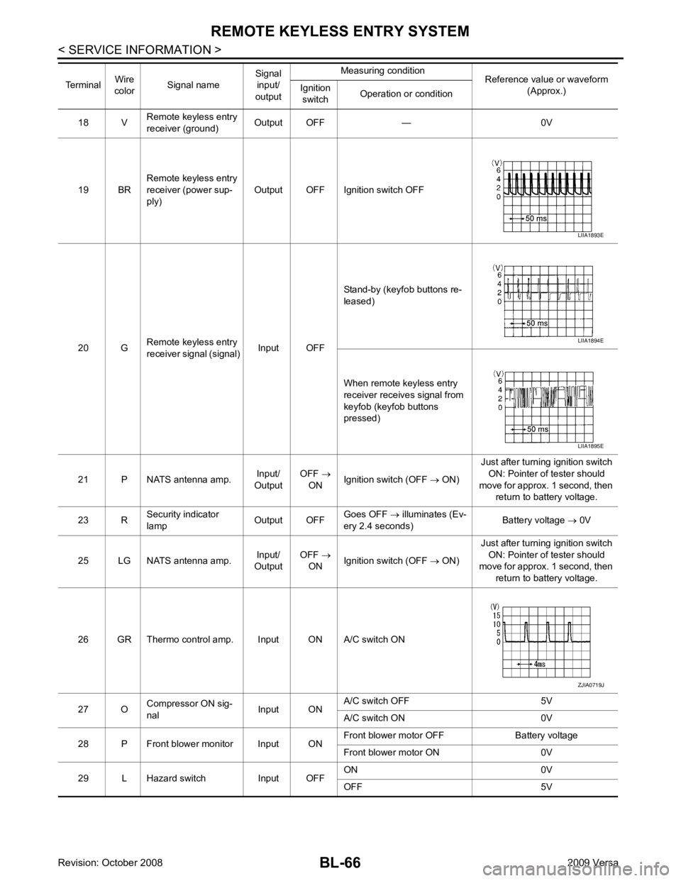
18 V Remote keyless entry
receiver (ground) Output OFF — 0V
19 BR Remote keyless entry
receiver (power sup-
ply) Output OFF Ignition switch OFF
20 G Remote keyless entry
receiver signal (signal) Input OFFStand-by (keyfob buttons re-
leased)
When remote keyless entry
receiver receives signal from
keyfob (keyfob buttons
pressed)
21 P NATS antenna amp. Input/
Output OFF
→
ON Ignition switch (OFF
→ ON) Just after turning ignition switch
ON: Pointer of tester should
move for approx. 1 second, then return to battery voltage.
23 R Security indicator
lamp Output OFFGoes OFF
→ illuminates (Ev-
ery 2.4 seconds) Battery voltage
→ 0V
25 LG NATS antenna amp. Input/
Output OFF
→
ON Ignition switch (OFF
→ ON) Just after turning ignition switch
ON: Pointer of tester should
move for approx. 1 second, then
return to battery voltage.
26 GR Thermo control amp. Input ON A/C switch ON
27 O Compressor ON sig-
nal Input ONA/C switch OFF 5V
A/C switch ON 0V
28 P Front blower monitor Input ON Front blower motor OFF Battery voltage
Front blower motor ON 0V
29 L Hazard switch Input OFF ON 0V
OFF 5V
Terminal
Wire
color Signal name Signal
input/
output Measuring condition
Reference value or waveform
(Approx.)
Ignition
switch Operation or condition LIIA1893E
LIIA1894E
LIIA1895E
ZJIA0719J
Page 573 of 4331
BL-112< SERVICE INFORMATION >
INTELLIGENT KEY SYSTEM
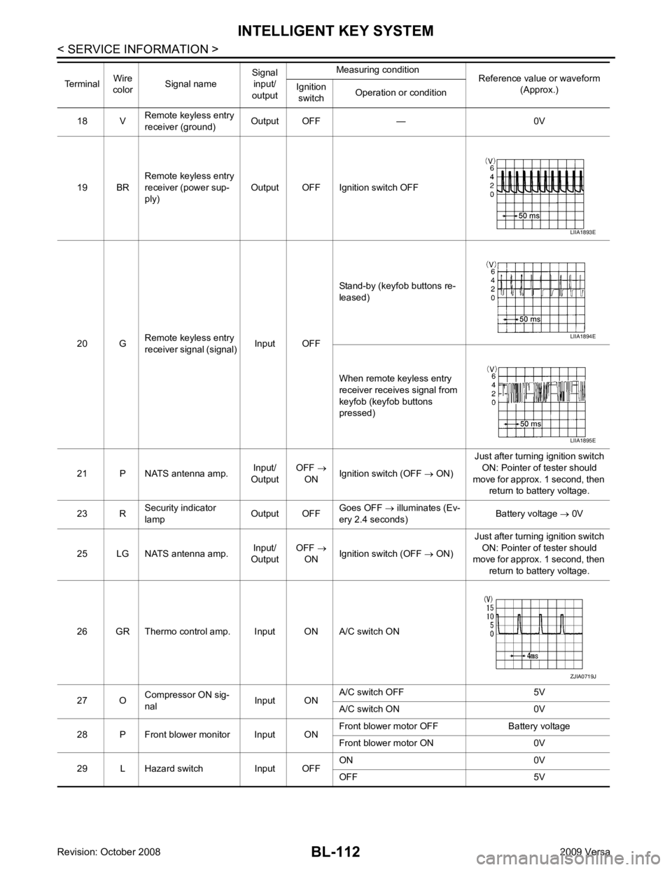
18 V Remote keyless entry
receiver (ground) Output OFF — 0V
19 BR Remote keyless entry
receiver (power sup-
ply) Output OFF Ignition switch OFF
20 G Remote keyless entry
receiver signal (signal) Input OFFStand-by (keyfob buttons re-
leased)
When remote keyless entry
receiver receives signal from
keyfob (keyfob buttons
pressed)
21 P NATS antenna amp. Input/
Output OFF
→
ON Ignition switch (OFF
→ ON) Just after turning ignition switch
ON: Pointer of tester should
move for approx. 1 second, then return to battery voltage.
23 R Security indicator
lamp Output OFFGoes OFF
→ illuminates (Ev-
ery 2.4 seconds) Battery voltage
→ 0V
25 LG NATS antenna amp. Input/
Output OFF
→
ON Ignition switch (OFF
→ ON) Just after turning ignition switch
ON: Pointer of tester should
move for approx. 1 second, then
return to battery voltage.
26 GR Thermo control amp. Input ON A/C switch ON
27 O Compressor ON sig-
nal Input ONA/C switch OFF 5V
A/C switch ON 0V
28 P Front blower monitor Input ON Front blower motor OFF Battery voltage
Front blower motor ON 0V
29 L Hazard switch Input OFF ON 0V
OFF 5V
Terminal
Wire
color Signal name Signal
input/
output Measuring condition
Reference value or waveform
(Approx.)
Ignition
switch Operation or condition LIIA1893E
LIIA1894E
LIIA1895E
ZJIA0719J
Page 578 of 4331
BL
N
O P
• Intelligent Key button
OK or NG OK >> GO TO 6
NG >> Refer to BL-119, " Trouble Diagnosis Symptom Chart " .
System
Description " .
OK or NG OK >> GO TO 7
NG >> Refer to BL-119, " Trouble Diagnosis Symptom Chart " .
System
Description " .
OK or NG OK >> Inspection End.
NG >> Refer to BL-119, " Trouble Diagnosis Symptom Chart " .
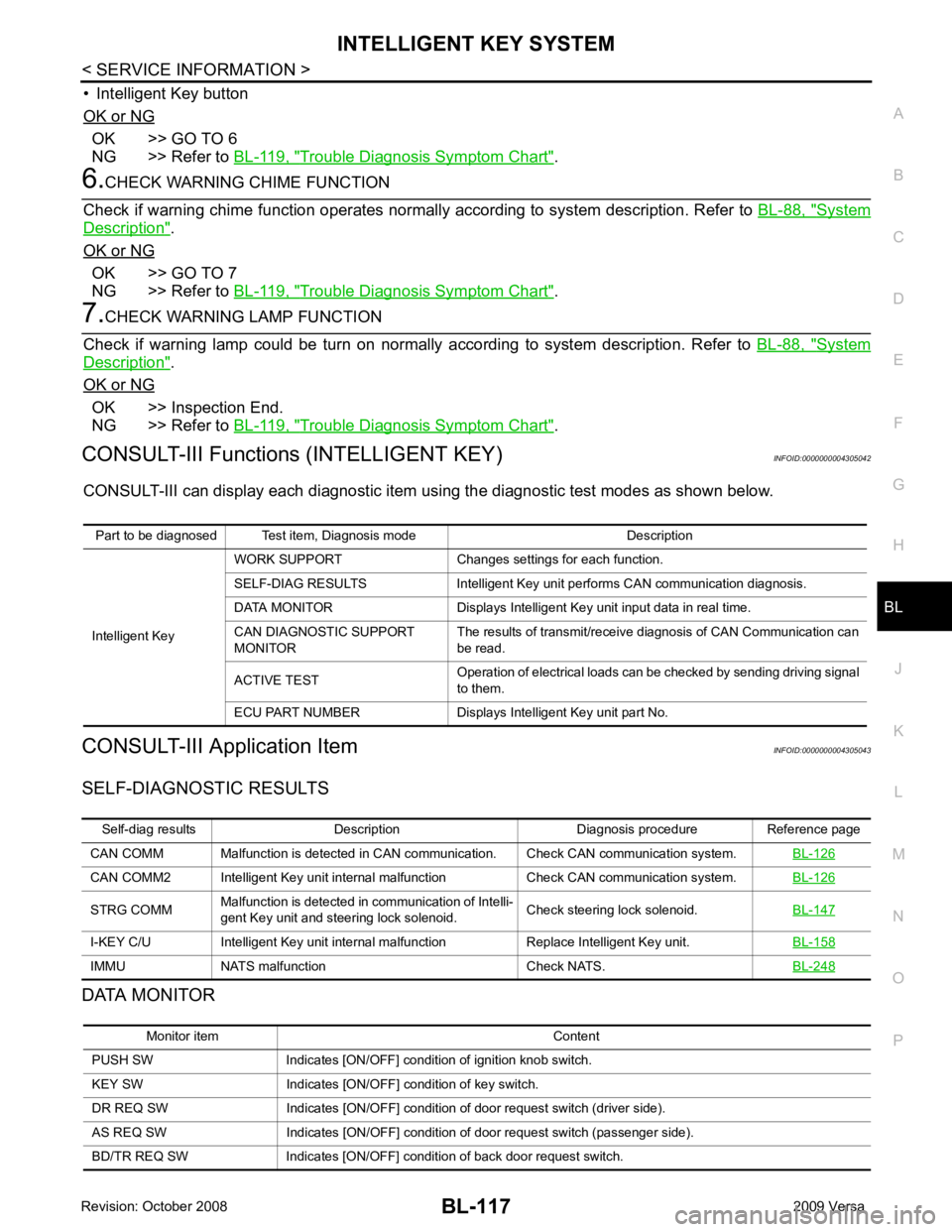
CONSULT-III Functions (INTELLIGENT KEY) INFOID:0000000004305042
CONSULT-III can display each diagnostic item using the diagnostic test modes as shown below.
CONSULT-III Application Item INFOID:0000000004305043
SELF-DIAGNOSTIC RESULTS
DATA MONITOR Part to be diagnosed Test item, Diagnosis mode Description
Intelligent Key WORK SUPPORT Changes settings for each function.
SELF-DIAG RESULTS Intelligent Key unit performs CAN communication diagnosis.
DATA MONITOR Displays Intelligent Key unit input data in real time.
CAN DIAGNOSTIC SUPPORT
MONITOR The results of transmit/receive diagnosis of CAN Communication can
be read.
ACTIVE TEST Operation of electrical loads can be checked by sending driving signal
to them.
ECU PART NUMBER Displays Intelligent Key unit part No. Self-diag results Description Diagnosis procedure Reference page
CAN COMM Malfunction is detected in CAN co mmunication. Check CAN communication system. BL-126CAN COMM2 Intelligent Key unit internal malfunction Check CAN communication system.
BL-126STRG COMM
Malfunction is detected in communication of Intelli-
gent Key unit and steering lock solenoid. Check steering lock solenoid.
BL-147I-KEY C/U Intelligent Key unit internal ma
lfunction Replace Intelligent Key unit. BL-158IMMU NATS malfunction Check NATS.
BL-248Monitor item Content
PUSH SW Indicates [ON/OFF] condition of ignition knob switch.
KEY SW Indicates [ON/OFF] condition of key switch.
DR REQ SW Indicates [ON/OFF] condition of door request switch (driver side).
AS REQ SW Indicates [ON/OFF] condition of door request switch (passenger side).
BD/TR REQ SW Indicates [ON/OFF] condition of back door request switch.
Page 637 of 4331
BL-176< SERVICE INFORMATION >
BACK DOOR LOCK
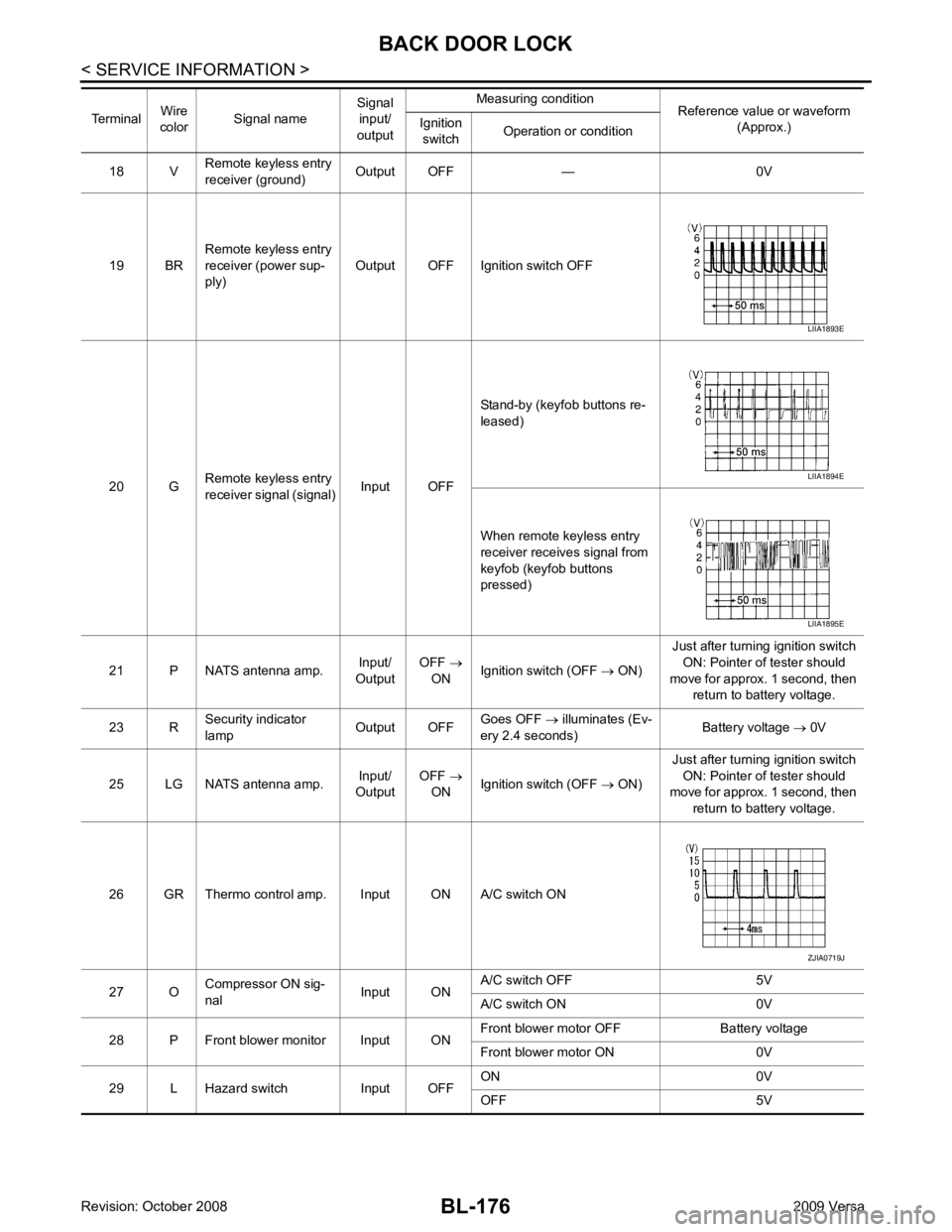
18 V Remote keyless entry
receiver (ground) Output OFF — 0V
19 BR Remote keyless entry
receiver (power sup-
ply) Output OFF Ignition switch OFF
20 G Remote keyless entry
receiver signal (signal) Input OFFStand-by (keyfob buttons re-
leased)
When remote keyless entry
receiver receives signal from
keyfob (keyfob buttons
pressed)
21 P NATS antenna amp. Input/
Output OFF
→
ON Ignition switch (OFF
→ ON) Just after turning ignition switch
ON: Pointer of tester should
move for approx. 1 second, then return to battery voltage.
23 R Security indicator
lamp Output OFFGoes OFF
→ illuminates (Ev-
ery 2.4 seconds) Battery voltage
→ 0V
25 LG NATS antenna amp. Input/
Output OFF
→
ON Ignition switch (OFF
→ ON) Just after turning ignition switch
ON: Pointer of tester should
move for approx. 1 second, then
return to battery voltage.
26 GR Thermo control amp. Input ON A/C switch ON
27 O Compressor ON sig-
nal Input ONA/C switch OFF 5V
A/C switch ON 0V
28 P Front blower monitor Input ON Front blower motor OFF Battery voltage
Front blower motor ON 0V
29 L Hazard switch Input OFF ON 0V
OFF 5V
Terminal
Wire
color Signal name Signal
input/
output Measuring condition
Reference value or waveform
(Approx.)
Ignition
switch Operation or condition LIIA1893E
LIIA1894E
LIIA1895E
ZJIA0719J
Page 642 of 4331
BACK DOOR LOCK
BL-181
< SERVICE INFORMATION >
C
D E
F
G H
J
K L
M A
B BL
N
O P
*1: With continuously variable transmission (CVT) or automatic transmission (A/T).
*2: With manual transmission (M/T).
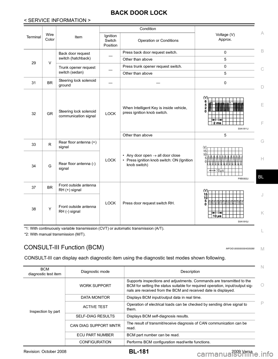
CONSULT-III Function (BCM) INFOID:0000000004305088
CONSULT-III can display each diagnostic item using the diagnostic test modes shown following. 29 V
Back door request
switch (hatchback) —Press back door request switch. 0
Other than above 5
Trunk opener request
switch (sedan) —Press trunk opener request switch. 0
Other than above 5
31 BR Steering lock solenoid
ground — — 0
32 GR Steering lock solenoid
communication signal LOCKWhen Intelligent Key is inside vehicle,
press ignition knob switch.
Other than above 5
33 R Rear floor antenna (+)
signal
LOCK• Any door open
→ all door close
• Press ignition knob switch: ON (Ignition
knob switch)
34 G Rear floor antenna (-)
signal
37 BR Front outside antenna
RH (+) signal
LOCK Press door request switch RH.
38 Y Front outside antenna
RH (-) signal
Terminal
Wire
Color Item Condition
Voltage (V)Approx.
Ignition
Switch
Position Operation or Conditions SIIA1911J
PIIB5502J
SIIA1910J
BCM
diagnostic test item Diagnostic mode Description
Inspection by part WORK SUPPORT
Supports inspections and adjustments. Commands are transmitted to the
BCM for setting the status suitable for required operation, input/output sig-
nals are received from the BCM and received date is displayed.
DATA MONITOR Displays BCM input/output data in real time.
ACTIVE TEST Operation of electrical loads can be checked by sending drive signal to
them.
SELF-DIAG RESULTS Displays BC M self-diagnosis results.
CAN DIAG SUPPORT MNTR The result of transmit/receive diagnosis of CAN communication can be
read.
ECU PART NUMBER BCM part number can be read.
CONFIGURATION Performs BCM configuration read/write functions.
Page 661 of 4331
BL-200< SERVICE INFORMATION >
TRUNK LID OPENER
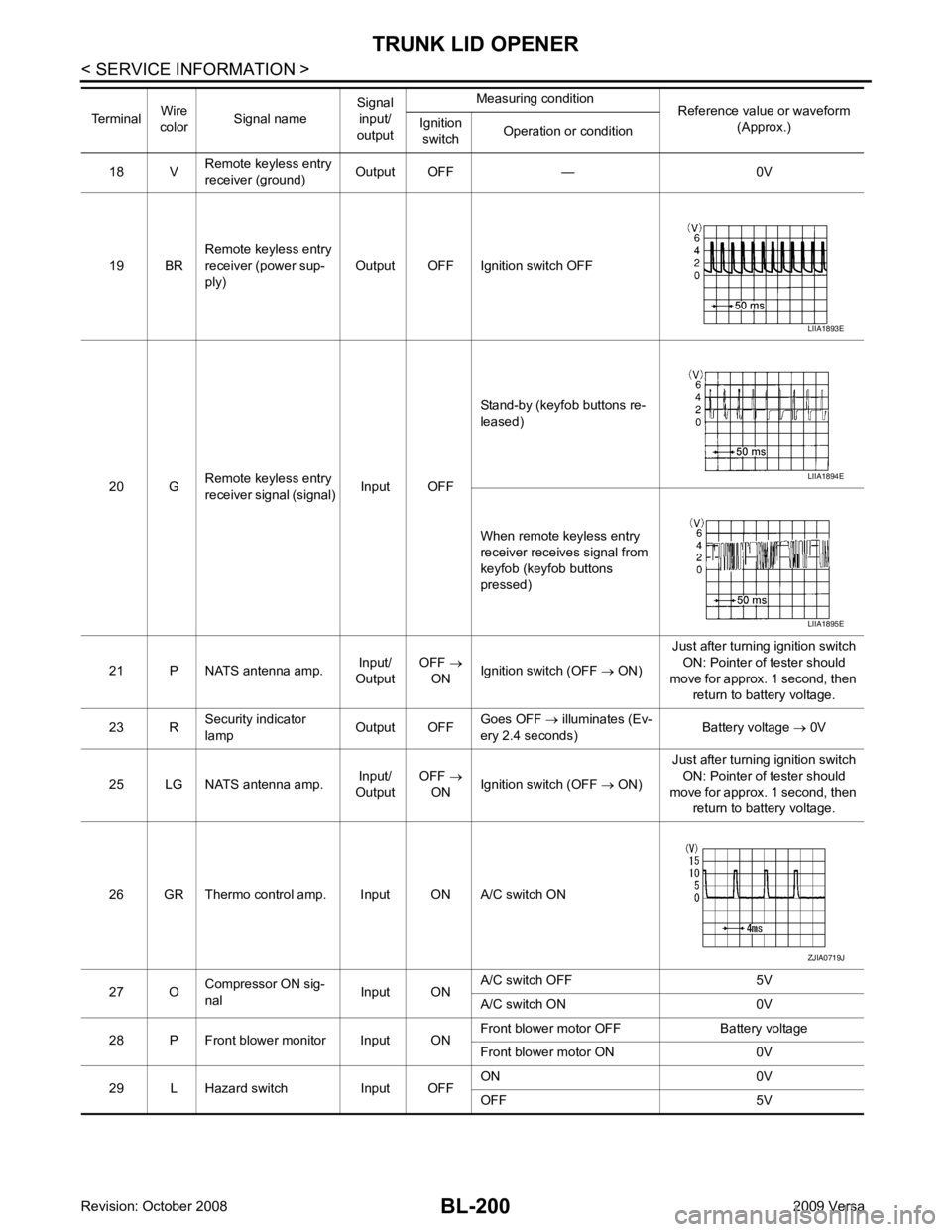
18 V Remote keyless entry
receiver (ground) Output OFF — 0V
19 BR Remote keyless entry
receiver (power sup-
ply) Output OFF Ignition switch OFF
20 G Remote keyless entry
receiver signal (signal) Input OFFStand-by (keyfob buttons re-
leased)
When remote keyless entry
receiver receives signal from
keyfob (keyfob buttons
pressed)
21 P NATS antenna amp. Input/
Output OFF
→
ON Ignition switch (OFF
→ ON) Just after turning ignition switch
ON: Pointer of tester should
move for approx. 1 second, then return to battery voltage.
23 R Security indicator
lamp Output OFFGoes OFF
→ illuminates (Ev-
ery 2.4 seconds) Battery voltage
→ 0V
25 LG NATS antenna amp. Input/
Output OFF
→
ON Ignition switch (OFF
→ ON) Just after turning ignition switch
ON: Pointer of tester should
move for approx. 1 second, then
return to battery voltage.
26 GR Thermo control amp. Input ON A/C switch ON
27 O Compressor ON sig-
nal Input ONA/C switch OFF 5V
A/C switch ON 0V
28 P Front blower monitor Input ON Front blower motor OFF Battery voltage
Front blower motor ON 0V
29 L Hazard switch Input OFF ON 0V
OFF 5V
Terminal
Wire
color Signal name Signal
input/
output Measuring condition
Reference value or waveform
(Approx.)
Ignition
switch Operation or condition LIIA1893E
LIIA1894E
LIIA1895E
ZJIA0719J