2009 NISSAN LATIO check engine
[x] Cancel search: check enginePage 1249 of 4331

CVT
N
O P
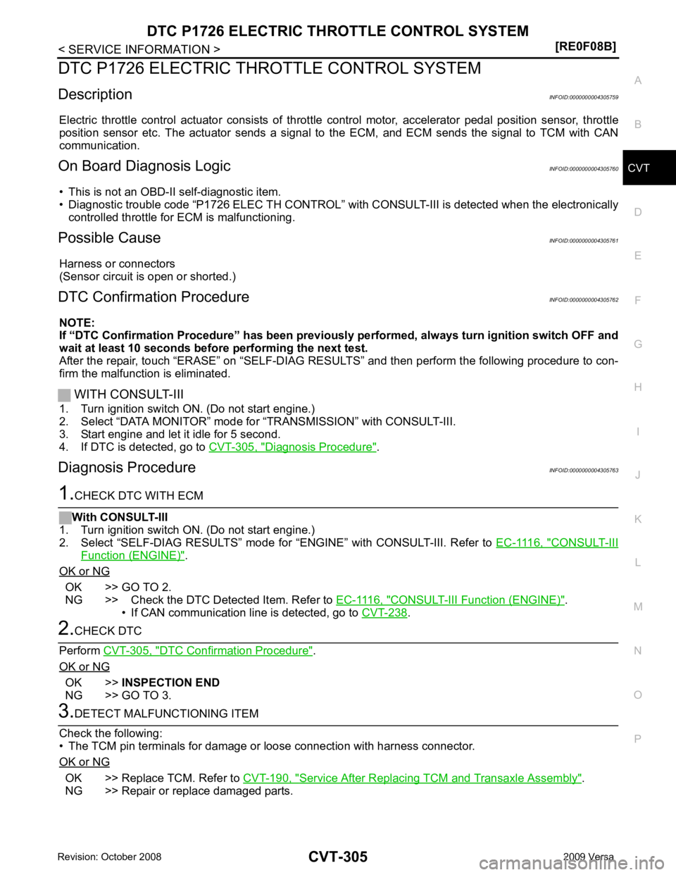
DTC P1726 ELECTRIC TH
ROTTLE CONTROL SYSTEM
Description INFOID:0000000004305759
Electric throttle control actuator consists of throttle control motor, accelerator pedal position sensor, throttle
position sensor etc. The actuator sends a signal to the ECM, and ECM sends the signal to TCM with CAN
communication.
On Board Diagnosis Logic INFOID:0000000004305760
• This is not an OBD-II self-diagnostic item.
• Diagnostic trouble code “P1726 ELEC TH CONTROL” wit h CONSULT-III is detected when the electronically
controlled throttle for ECM is malfunctioning.
Possible Cause INFOID:0000000004305761
Harness or connectors
(Sensor circuit is open or shorted.)
DTC Confirmation Procedure INFOID:0000000004305762
NOTE:
If “DTC Confirmation Procedure” has been previously performed, alw ays turn ignition switch OFF and
wait at least 10 seconds before performing the next test.
After the repair, touch “ERASE” on “SELF-DIAG RESU LTS” and then perform the following procedure to con-
firm the malfunction is eliminated.
WITH CONSULT-III
1. Turn ignition switch ON. (Do not start engine.)
2. Select “DATA MONITOR” mode for “TRANSMISSION” with CONSULT-III.
3. Start engine and let it idle for 5 second.
4. If DTC is detected, go to CVT-305, " Diagnosis Procedure " .
Diagnosis Procedure INFOID:0000000004305763 CONSULT-III
Function (ENGINE) " .
OK or NG OK >> GO TO 2.
NG >> Check the DTC Detected Item. Refer to EC-1116, " CONSULT-III Function (ENGINE) " .
• If CAN communication line is detected, go to CVT-238 .
DTC Confirmation Procedure " .
OK or NG OK >>
INSPECTION END
NG >> GO TO 3. OK >> Replace TCM. Refer to
CVT-190, " Service After Replacing TCM and Transaxle Assembly " .
NG >> Repair or replace damaged parts.
Page 1257 of 4331
![NISSAN LATIO 2009 Service Repair Manual DTC P1777 STEP MOTOR - CIRCUIT
CVT-313
< SERVICE INFORMATION >
[RE0F08B] D
E
F
G H
I
J
K L
M A
B CVT
N
O P
Diagnosis Procedure
INFOID:00000000043057831.
CHECK INPUT SIGNALS
With CONSULT-III
1. Start e NISSAN LATIO 2009 Service Repair Manual DTC P1777 STEP MOTOR - CIRCUIT
CVT-313
< SERVICE INFORMATION >
[RE0F08B] D
E
F
G H
I
J
K L
M A
B CVT
N
O P
Diagnosis Procedure
INFOID:00000000043057831.
CHECK INPUT SIGNALS
With CONSULT-III
1. Start e](/manual-img/5/57359/w960_57359-1256.png)
DTC P1777 STEP MOTOR - CIRCUIT
CVT-313
< SERVICE INFORMATION >
[RE0F08B] D
E
F
G H
I
J
K L
M A
B CVT
N
O P
Diagnosis Procedure
INFOID:00000000043057831.
CHECK INPUT SIGNALS
With CONSULT-III
1. Start engine.
2. Select “SELECTION FROM MENU” in “DATA MONI TOR” mode for “TRANSMISSION” with CONSULT-III.
3. Start vehicle and read out the value of “STM STEP”, “SMCOIL A”, “SMCOIL B”, “SMCOIL C”, and
“SMCOIL D”.
OK or NG OK >> GO TO 4.
NG >> GO TO 2. 2.
CHECK HARNESS BETWEEN TCM AND STEP MOTOR
1. Turn ignition switch OFF.
2. Disconnect CVT unit connector and TCM connector.
3. Check continuity between TCM connector terminals and CVT
unit harness connector terminals.
4. If OK, check harness for short to ground and short to power.
5. If OK, check continuity between body ground and CVT assembly.
6. Reinstall any part removed.
OK or NG OK >> GO TO 3.
NG >> Repair open circuit or short to ground or short to power in harness or connectors. 3.
CHECK STEP MOTOR
Check step motor. Refer to CVT-314, " Component Inspection " .
OK or NG OK >> GO TO 4.
NG >> Repair or replace damaged parts. 4.
CHECK DTC
Perform CVT-311, " DTC Confirmation Procedure " .
OK or NG OK >>
INSPECTION END
NG >> GO TO 5.
Item name Condition Display value (Approx.)
STM STEP
During driving−
20 step - 180 step
SMCOIL A
Changes ON⇔OFF.
SMCOIL B
SMCOIL C
SMCOIL D Item Connector Terminal Continuity
TCM E31 11 Yes
CVT unit harness connector F46 6
TCM E31 12 Yes
CVT unit harness connector F46 7
TCM E31 20 Yes
CVT unit harness connector F46 8
TCM E31 21 Yes
CVT unit harness connector F46 9 SCIA4695E
Page 1260 of 4331

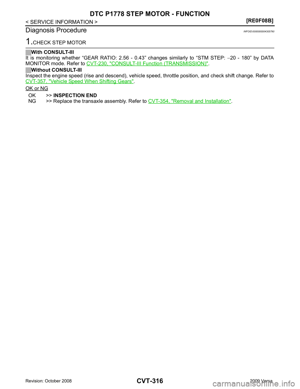
CONSULT-III Function (TRANSMISSION) " .
Without CONSULT-III
Inspect the engine speed (rise and descend), vehicle speed, throttle position, and check shift change. Refer to
CVT-357, " Vehicle Speed When Shifting Gears " .
OK or NG OK >>
INSPECTION END
NG >> Replace the transaxle assembly. Refer to CVT-354, " Removal and Installation " .
Page 1271 of 4331

CVT
N
O P
Check again. Refer to
CVT-224, " Check before Engine Is Started " .
OK or NG OK >>
INSPECTION END
NG >> GO TO 7. OK or NG
OK >>
INSPECTION END
NG >> Repair or replace damaged parts.
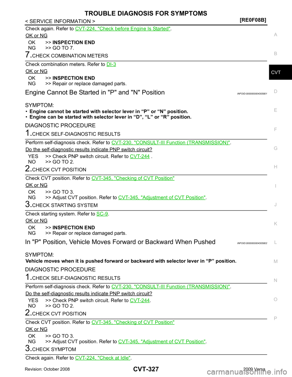
Engine Cannot Be Starte d in "P" and "N" Position INFOID:0000000004305801
SYMPTOM: • Engine cannot be started with select or lever in “P” or “N” position.
• Engine can be started with selector lever in “D”, “L” or “R” position.
DIAGNOSTIC PROCEDURE CONSULT-III Functi
on (TRANSMISSION) " .
Do the self-diagnostic results indicate PNP switch circuit? YES >> Check PNP switch circuit. Refer to
CVT-244 .
NO >> GO TO 2. Checking of CVT Position "
OK or NG
OK >> GO TO 3.
NG >> Adjust CVT position. Refer to CVT-345, " Adjustment of CVT Position " .
.
OK or NG OK >>
INSPECTION END
NG >> Repair or replace damaged parts.
In "P" Position, Vehicle Moves Forward or Backward When Pushed INFOID:0000000004305802
SYMPTOM: Vehicle moves when it is pushed forward or backward with selector lever in “P” position.
DIAGNOSTIC PROCEDURE CONSULT-III Functi
on (TRANSMISSION) " .
Do the self-diagnostic results indicate PNP switch circuit? YES >> Check PNP switch circuit. Refer to
CVT-244 .
NO >> GO TO 2. Checking of CVT Position "
OK or NG
OK >> GO TO 3.
NG >> Adjust CVT position. Refer to CVT-345, " Adjustment of CVT Position " .
Check at Idle " .
Page 1277 of 4331

CVT
N
O P
OK >> Replace the transaxle assembly. Refer to
CVT-354, " Removal and Installation " .
NG >> Repair or replace damaged parts.
Vehicle Speed Does Not Change in "D" Position INFOID:0000000004305809
SYMPTOM: Vehicle speed does not change in “D” position while the cruise test.
DIAGNOSTIC PROCEDURE CONSULT-III Functi
on (TRANSMISSION) " .
Is any malfunction detected by self-diagnosis? YES >> Check the malfuncti
oning system. Refer to CVT-230, " CONSULT-III Function (TRANSMISSION) "
.
NO >> GO TO 2. Checking of CVT Position "
OK or NG
OK >> GO TO 3.
NG >> Adjust CVT position. Refer to CVT-345, " Adjustment of CVT Position " .
Checking CVT Fluid " .
OK or NG OK >> GO TO 4.
NG >> Refill CVT fluid. Inspections before Trouble Diagnosis " .
OK or NG OK >> GO TO 5.
NG >> Check the malfunctioning item. Refer to CVT-219, " Inspections before Trouble Diagnosis " .
Inspections before Trouble Diagnosis " .
OK or NG OK >> GO TO 6.
NG >> Check the malfunctioning item. Refer to CVT-219, " Inspections before Trouble Diagnosis " .
Cruise Test " .
OK or NG OK >>
INSPECTION END
NG >> GO TO 7. TCM Terminal and Reference Value " .
2. If NG, re-check TCM pin terminals for dam age or loose connection with harness connector.
OK or NG OK >> Replace the transaxle assembly. Refer to
CVT-354, " Removal and Installation " .
NG >> Repair or replace damaged parts.
Vehicle Does Not Decelerate by Engine Brake INFOID:0000000004305810
SYMPTOM: Engine brake does not operate when releasing the accelerator pedal while the cruise test.
Page 1281 of 4331
![NISSAN LATIO 2009 Service Repair Manual CVT SHIFT LOCK SYSTEM
CVT-337
< SERVICE INFORMATION >
[RE0F08B] D
E
F
G H
I
J
K L
M A
B CVT
N
O P
•
Selector lever can be moved fr om “P” position with ignition key in ON position NISSAN LATIO 2009 Service Repair Manual CVT SHIFT LOCK SYSTEM
CVT-337
< SERVICE INFORMATION >
[RE0F08B] D
E
F
G H
I
J
K L
M A
B CVT
N
O P
•
Selector lever can be moved fr om “P” position with ignition key in ON position](/manual-img/5/57359/w960_57359-1280.png)
CVT SHIFT LOCK SYSTEM
CVT-337
< SERVICE INFORMATION >
[RE0F08B] D
E
F
G H
I
J
K L
M A
B CVT
N
O P
•
Selector lever can be moved fr om “P” position with ignition key in ON position and brake pedal
released.
• Selector lever can be moved from “P” position when ignition switch is removed from key cylinder.
SYMPTOM 2:
• Ignition key cannot be removed when sel ector lever is set to “P” position.
• Ignition key can be removed wh en selector lever is set to any position except “P” position.1.
CHECK KEY INTERLOCK CABLE
Check key interlock cable for damage.
OK or NG OK >> GO TO 2.
NG >> Repair key interlock cable. Refer to AT-218, " Removal and Installation " .
2.
CHECK CVT POSITION
Check CVT position. Refer to CVT-345, " Checking of CVT Position " .
OK or NG OK >> GO TO 3.
NG >> Adjust control cable. Refer to CVT-345, " Adjustment of CVT Position " .
3.
CHECK SHIFT LOCK SOLENOID AND PARK POSITION SWITCH
1. Turn ignition switch ON. (Do not start engine.)
2. Selector lever is set in “P” position.
3. Check operation sound.
OK or NG OK >>
INSPECTION END
NG - 1 >> With intelligent key: GO TO 4.
NG - 2 >> Without intelligent key: GO TO 5. 4.
CHECK POWER SOURCE
1. Turn ignition switch ON. (Do not start engine.)
2. Check voltage between CVT device harness connector terminal 5 and ground.
OK or NG OK >> GO TO 8.
NG >> GO TO 6. 5.
CHECK POWER SOURCE
1. Turn ignition switch ON. (Do not start engine.) Condition Brake pedal Operation sound
When ignition switch is turned to ON position and selector lever is set in
“P” position. Depressed Yes
Released No Voltage:
Brake pedal depressed: Battery voltage
Brake pedal released: 0V SCIA7934E
Page 1289 of 4331
![NISSAN LATIO 2009 Service Repair Manual SHIFT CONTROL SYSTEM
CVT-345
< SERVICE INFORMATION >
[RE0F08B] D
E
F
G H
I
J
K L
M A
B CVT
N
O P
1. Set selector lever knob (1) in “N” position.
2. Slide knob cover (2) downward.
3. Pull out lock NISSAN LATIO 2009 Service Repair Manual SHIFT CONTROL SYSTEM
CVT-345
< SERVICE INFORMATION >
[RE0F08B] D
E
F
G H
I
J
K L
M A
B CVT
N
O P
1. Set selector lever knob (1) in “N” position.
2. Slide knob cover (2) downward.
3. Pull out lock](/manual-img/5/57359/w960_57359-1288.png)
SHIFT CONTROL SYSTEM
CVT-345
< SERVICE INFORMATION >
[RE0F08B] D
E
F
G H
I
J
K L
M A
B CVT
N
O P
1. Set selector lever knob (1) in “N” position.
2. Slide knob cover (2) downward.
3. Pull out lock pin (3) from selector lever knob (1).
4. Remove selector lever knob (1) and knob cover (2) as a set from selector lever.
CAUTION:
Do not push selector button.
INSTALLATION 1. Insert lock pin (1) to selector lever knob (2).
2. Install knob cover (3) to selector lever knob (2).
3. Set selector lever in “N” position.
4. Install selector lever knob onto selector lever until a click is felt. CAUTION:
• Do not tilt selector lever knob when installing. Install it
straight, and do not tap or ap ply any shock to install it.
• Do not push selector button.
Adjustment of CVT Position INFOID:0000000004305819
CAUTION:
Make sure that parking brake is applied before adjustment.
1. Loosen the control cable nut (A) and place the manual lever (1) in “P” position.
2. Place selector lever in “P” position.
3. Push the control cable (2) in with a load of 9.8 N (approximately 1 kg, 2.2 lb). Release the control cable and temporarily tighten
the control cable nut.
NOTE:
Do not move the manual lever. Make sure the manual lever
stays in the “P” position.
4. Tighten the control cable nut. CAUTION:
Secure the manual lever when tightening nut.
5. Check the operation of the CVT. Refer to CVT-345, " Checking of CVT Position " .
Checking of CVT Position INFOID:0000000004305820
1. Place selector lever in “P” position, and tu rn ignition switch ON. (Do not start engine.)
2. Make sure selector lever can be shifted to other than “P” position when brake pedal is depressed. Also
make sure selector lever can be shifted from “P” position only when brake pedal is depressed.
3. Move the selector lever and check for excessive effort, sticking, noise or rattle.
4. Confirm the selector lever stops at each position with the feel of engagement when it is moved through all
the positions. Check that t he actual position of the selector lever matches the position shown by the shift
position indicator and the manual lever on the transaxle. SCIA6971E
SCIA6972E
Control cable nut: Refer to
CVT-341, " Removal
and Installation " . WCIA0608E
Page 1299 of 4331
![NISSAN LATIO 2009 Service Repair Manual TRANSAXLE ASSEMBLY
CVT-355
< SERVICE INFORMATION >
[RE0F08B] D
E
F
G H
I
J
K L
M A
B CVT
N
O P
4. Remove the four drive plate to torque converter nuts.
NOTE:
Rotate the crankshaft clockwise as vi NISSAN LATIO 2009 Service Repair Manual TRANSAXLE ASSEMBLY
CVT-355
< SERVICE INFORMATION >
[RE0F08B] D
E
F
G H
I
J
K L
M A
B CVT
N
O P
4. Remove the four drive plate to torque converter nuts.
NOTE:
Rotate the crankshaft clockwise as vi](/manual-img/5/57359/w960_57359-1298.png)
TRANSAXLE ASSEMBLY
CVT-355
< SERVICE INFORMATION >
[RE0F08B] D
E
F
G H
I
J
K L
M A
B CVT
N
O P
4. Remove the four drive plate to torque converter nuts.
NOTE:
Rotate the crankshaft clockwise as viewed from front of engine
for access to drive plate to torque converter nuts.
5. Put matching marks on the drive plate and torque converter alignment stud. CAUTION:
For matching marks, use paint. Never dama ge the drive plate or torque converter.
6. Remove the transaxle to engine and engine to transaxle bolts.
7. Separate the transaxle from the engine.
8. If necessary, remove the following from the transaxle: • CVT fluid charging pipe
• Engine mounting bracket (LH)
• Fluid cooler tubes
• Air breather hose
• Any necessary brackets
INSTALLATION Installation is in the reverse order of removal.
CAUTION:
• When replacing an engine or transmission you mu st make sure any dowels are installed correctly
during re-assembly.
• Improper alignment caused by missing dowels m ay cause vibration, oil leaks or breakage of drive
train components.
• Do not reuse O-rings and copper washers.
• When turning crankshaft, turn it clockwise as viewed from the front of the engine.
• When tightening the nuts for the torque converter while securing the crankshaft pulley bolt, be sure
to confirm the tightening torque of the crankshaft pulley bolt. Refer to EM-160 .
• After converter is installed to drive plate, ro tate crankshaft several turns to check that transaxle
rotates freely without binding.
• When installing the torque converter to the transaxle measure dis- tance A. WCIA0616E
Distance A: 14.4 mm (0.57 in) or more
WCIA0617E