2009 NISSAN LATIO brake pads
[x] Cancel search: brake padsPage 827 of 4331
BR
N
O P
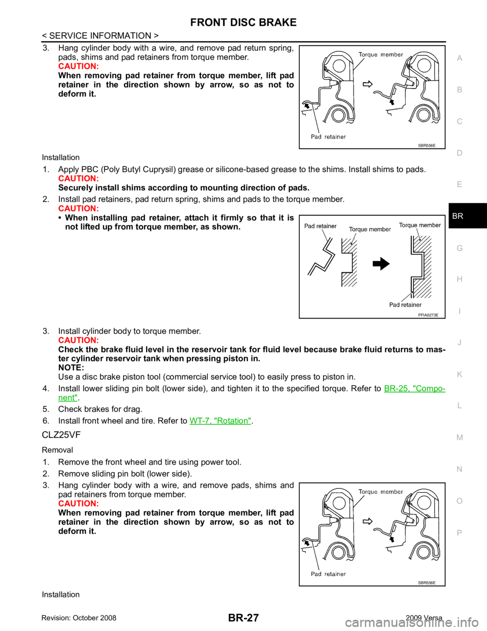
3. Hang cylinder body with a wire, and remove pad return spring,
pads, shims and pad retainers from torque member.
CAUTION:
When removing pad retainer from torque member, lift pad
retainer in the direction shown by arrow, so as not to
deform it.
Installation 1. Apply PBC (Poly Butyl Cuprysil) grease or silicone- based grease to the shims. Install shims to pads.
CAUTION:
Securely install shims according to mounting direction of pads.
2. Install pad retainers, pad return spring, shims and pads to the torque member. CAUTION:
• When installing pad retainer, at tach it firmly so that it is
not lifted up from torque member, as shown.
3. Install cylinder body to torque member. CAUTION:
Check the brake fluid level in the reservoir tank for fluid level because brake fluid returns to mas-
ter cylinder reservoir tank when pressing piston in.
NOTE:
Use a disc brake piston tool (commercial se rvice tool) to easily press to piston in.
4. Install lower sliding pin bolt (lower side), and tighten it to the specified torque. Refer to BR-25, " Compo-
nent " .
5. Check brakes for drag.
6. Install front wheel and tire. Refer to WT-7, " Rotation " .
CLZ25VF
Removal 1. Remove the front wheel and tire using power tool.
2. Remove sliding pin bolt (lower side).
3. Hang cylinder body with a wire, and remove pads, shims and pad retainers from torque member.
CAUTION:
When removing pad retainer from torque member, lift pad
retainer in the direction shown by arrow, so as not to
deform it.
Installation SBR556E
Page 830 of 4331
BR-30< SERVICE INFORMATION >
FRONT DISC BRAKE
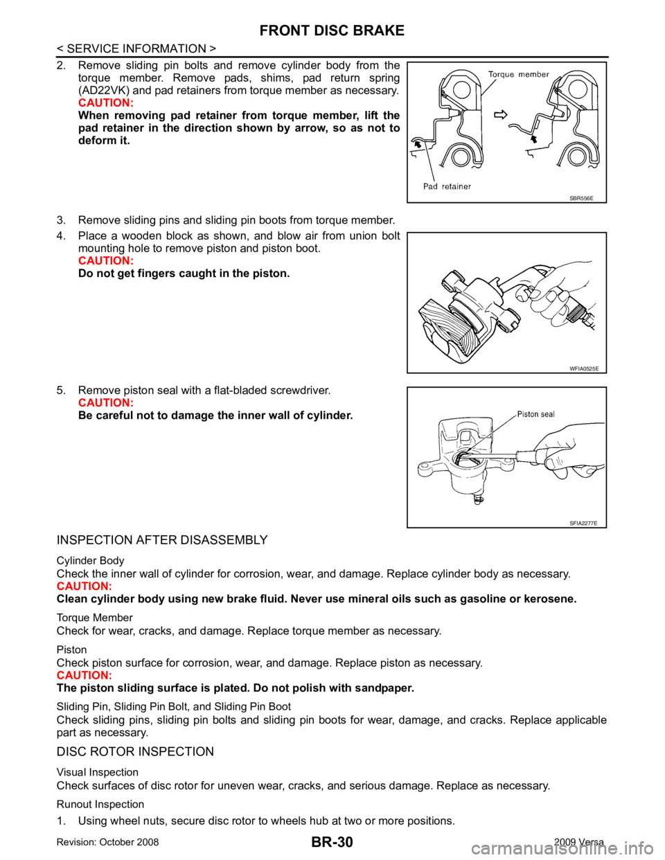
2. Remove sliding pin bolts and remove cylinder body from the torque member. Remove pads, shims, pad return spring
(AD22VK) and pad retainers from torque member as necessary.
CAUTION:
When removing pad retainer fr om torque member, lift the
pad retainer in the direction shown by arrow, so as not to
deform it.
3. Remove sliding pins and sliding pin boots from torque member.
4. Place a wooden block as shown, and blow air from union bolt mounting hole to remove piston and piston boot.
CAUTION:
Do not get fingers caught in the piston.
5. Remove piston seal with a flat-bladed screwdriver. CAUTION:
Be careful not to damage the inner wall of cylinder.
INSPECTION AFTER DISASSEMBLY
Cylinder Body
Check the inner wall of cylinder for corrosion, w ear, and damage. Replace cylinder body as necessary.
CAUTION:
Clean cylinder body using new brake fluid. Never use mineral oils such as gasoline or kerosene.
Torque Member
Check for wear, cracks, and damage. R eplace torque member as necessary.
Piston
Check piston surface for corrosion, wear, and damage. Replace piston as necessary.
CAUTION:
The piston sliding surface is plated . Do not polish with sandpaper.
Sliding Pin, Sliding Pin Bolt, and Sliding Pin Boot
Check sliding pins, sliding pin bolts and sliding pin boots for wear, damage, and cracks. Replace applicable
part as necessary.
DISC ROTOR INSPECTION
Visual Inspection
Check surfaces of disc rotor for uneven wear, cr acks, and serious damage. Replace as necessary.
Runout Inspection
1. Using wheel nuts, secure disc rotor to wheels hub at two or more positions. SBR556E
WFIA0525E
SFIA2277E
Page 832 of 4331
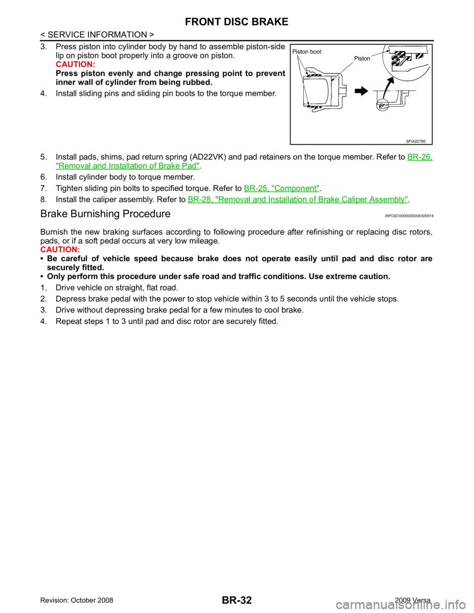
" Removal and Installation of Brake Pad " .
6. Install cylinder body to torque member.
7. Tighten sliding pin bolts to specified torque. Refer to BR-25, " Component " .
8. Install the caliper assembly. Refer to BR-28, " Removal and Installation of Brake Caliper Assembly " .
Brake Burnishing Procedure INFOID:0000000004305914
Burnish the new braking surfaces according to following procedure after refinishing or replacing disc rotors,
pads, or if a soft pedal occurs at very low mileage.
CAUTION:
• Be careful of vehicle speed because brake does not operate easily until pad and disc rotor are
securely fitted.
• Only perform this procedure under safe road and traffic conditions. Use extreme caution.
1. Drive vehicle on straight, flat road.
2. Depress brake pedal with the power to stop vehicl e within 3 to 5 seconds until the vehicle stops.
3. Drive without depressing brake pedal for a few minutes to cool brake.
4. Repeat steps 1 to 3 until pad and disc rotor are securely fitted.
Page 842 of 4331
![NISSAN LATIO 2009 Service Repair Manual BRC-2< SERVICE INFORMATION >
[ABS]
PRECAUTIONS
SERVICE INFORMATION
PRECAUTIONS
Precaution for Supplemental Restraint Syst em (SRS) "AIR BAG" and "SEAT BELT
PRE-TENSIONER" INFOID:0000000004784402
The NISSAN LATIO 2009 Service Repair Manual BRC-2< SERVICE INFORMATION >
[ABS]
PRECAUTIONS
SERVICE INFORMATION
PRECAUTIONS
Precaution for Supplemental Restraint Syst em (SRS) "AIR BAG" and "SEAT BELT
PRE-TENSIONER" INFOID:0000000004784402
The](/manual-img/5/57359/w960_57359-841.png)
BRC-2< SERVICE INFORMATION >
[ABS]
PRECAUTIONS
SERVICE INFORMATION
PRECAUTIONS
Precaution for Supplemental Restraint Syst em (SRS) "AIR BAG" and "SEAT BELT
PRE-TENSIONER" INFOID:0000000004784402
The Supplemental Restraint System such as “A IR BAG” and “SEAT BELT PRE-TENSIONER”, used along
with a front seat belt, helps to reduce the risk or severi ty of injury to the driver and front passenger for certain
types of collision. This system includes seat belt switch inputs and dual stage front air bag modules. The SRS
system uses the seat belt switches to determine the front air bag deployment, and may only deploy one front
air bag, depending on the severity of a collision and w hether the front occupants are belted or unbelted.
Information necessary to service the system safely is included in the SRS and SB section of this Service Man-
ual.
WARNING:
• To avoid rendering the SRS inopera tive, which could increase the risk of personal injury or death in
the event of a collision which would result in air bag inflation, all maintenance must be performed by
an authorized NISS AN/INFINITI dealer.
• Improper maintenance, including incorrect removal and installation of the SRS can lead to personal
injury caused by unintent ional activation of the system. For re moval of Spiral Cable and Air Bag
Module, see the SRS section.
• Do not use electrical test equipmen t on any circuit related to the SRS unless instructed to in this
Service Manual. SRS wiring harn esses can be identified by yellow and/or orange harnesses or har-
ness connectors.
PRECAUTIONS WHEN USING POWER TOOLS (AIR OR ELECTRIC) AND HAMMERS
WARNING:
• When working near the Airbag Diagnosis Sensor Unit or other Airbag System sensors with the Igni-
tion ON or engine running, DO NOT use air or electri c power tools or strike near the sensor(s) with a
hammer. Heavy vibration could activate the sensor( s) and deploy the air bag(s), possibly causing
serious injury.
• When using air or electric power tools or hammers , always switch the Ignition OFF, disconnect the
battery, and wait at least 3 minu tes before performing any service.
Precaution for Brake System INFOID:0000000004307251
CAUTION:
• Refer to MA-14 for recommended brake fluid.
• Never reuse drained brake fluid.
• Be careful not to splash brake fluid on painted areas; it may cause paint damage. If brake fluid is
splashed on painted areas, wash it away with water immediately.
• To clean or wash all parts of master cylin der and disc brake caliper, use clean brake fluid.
• Never use mineral oils such as gasoline or kerosene. They will ruin rubber parts of the hydraulic sys-
tem.
• Use flare nut wrench when re moving and installing brake
tube.
• If a brake fluid leak is found, the part must be disassembled
without fail. Then it has to be replaced with a new one if a
defect exists.
• Turn the ignition switch OFF an d remove the connector of the
ABS actuator and electric unit (c ontrol unit) or the battery ter-
minal before performing the work.
• Always torque brake lines when installing.
• Burnish the brake contact surf aces after refinishing or replac-
ing rotors, after replacing pads, or if a soft pedal occurs at
very low mileage. Refer to BR-32, " Brake Burnishing Proce-
dure " .
WARNING:
• Clean brake pads and shoes with a waste cloth, then wipe with a dust collector. SBR686C
Page 843 of 4331

BRC
N
O P
Precaution for Brake Control
INFOID:0000000004307252
• During ABS operation, the brake pedal may vibrate lightly and a mechanical noise may be heard. This is normal.
• Just after starting the vehicle, the brake pedal may vibrate or motor operating noises may be heard from
engine compartment. This is normal due to the self check operation.
• Stopping distance may be longer than that of vehicles without ABS when vehicle drives on rough, gravel, or
snow-covered (fresh, deep snow) roads.
• When an error is indicated by ABS or another warning lamp, collect all necessary information from customer
(what symptoms are present under what conditions) and check for simple causes before starting diagnosis.
Besides electrical system inspection, check brake booster operation, brake fluid level, and fluid leaks.
• If incorrect tire sizes or types are installed on the vehicle or brake pads are not Genuine NISSAN parts, stop-
ping distance or steering stability may deteriorate.
• If there is a radio, antenna or related wiring near t he control module, ABS function may have a malfunction
or error.
• If aftermarket parts (car stereo, CD player, etc.) have been installed, check for incidents such as harness pinches, open circuits or improper wiring.
Precaution for CAN System INFOID:0000000004307253
• Do not apply voltage of 7.0V or higher to terminal to be measured.
• Maximum open terminal voltage of tester in use must be less than 7.0V.
• Before checking harnesses, turn ignition switch OFF and disconnect battery negative cable.
• Area to be repaired must be soldered and wrapped with tape. Make sure that fraying of twisted wire is within 110 mm (4.33 in).
• Do not make a bypass connection to repaired area. (If the circuit is bypassed, characteristics of twisted wire will be lost.)
Page 857 of 4331
BRC
N
O P
• If ABS actuator and electric unit (control unit) connec
tion is loose, tighten the piping to the specified
torque and recheck for leaks.
• If there is damage to the connection flare nut or A BS actuator and electric unit (control unit) threads,
replace the damaged part and recheck for leaks.
• When there is fluid leaking or seeping from a fluid connection, use a clean cloth to wipe off the fluid and recheck for leaks. If fluid is still seeping out, repl ace the damaged part. If the fluid is leaking at the ABS
actuator and electric unit (control unit), replace the ABS actuator and electric unit (control unit) assem-
bly.
CAUTION:
The ABS actuator and electric unit (control un it) cannot be disassembled and must be replaced
as an assembly.
3. Check the brake pads for excessive wear.
POWER SYSTEM TERMINAL LOOSENESS AND BATTERY INSPECTION Make sure the battery positive cable, negative cabl e and ground connection are not loose. In addition, make
sure the battery is sufficiently charged.
ABS WARNING LAMP INSPECTION 1. Make sure ABS warning lamp turns on for approximately 2 seconds when the ignition switch is turned ON. If it does not, check CAN communications. If ther e are no errors with the CAN communication system,
replace the combination meter. Refer to IP-12, " Removal and Installation " .
2. Make sure the lamp turns off approximately 2 seconds after the ignition switch is turned ON. If the lamp does not turn off, conduct self-diagnosis of ABS act uator and electric unit (control unit). If no malfunctions
are detected in self-diagnosis, replace combination meter. Refer to IP-12, " Removal and Installation " .
3. After conducting the self-diagnosis, be sure to erase the error memory. Refer to BRC-18, " CONSULT-III
Function (ABS) " .
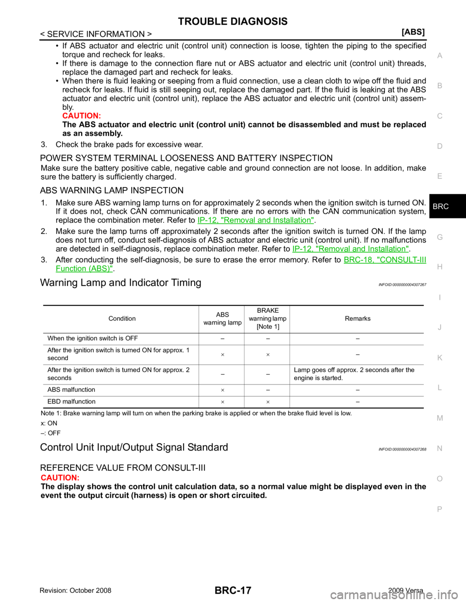
Warning Lamp and Indicator Timing INFOID:0000000004307267
Note 1: Brake warning lamp will turn on when the parking brake is applied or when the brake fluid level is low.
x: ON
–: OFF
Control Unit Input/Out put Signal Standard INFOID:0000000004307268
REFERENCE VALUE FROM CONSULT-III CAUTION:
The display shows the control unit calculation data, so a normal value might be displayed even in the
event the output circuit (harness) is open or short circuited.
Condition
ABS
warning lamp BRAKE
warning lamp [Note 1] Remarks
When the ignition switch is OFF – – –
After the ignition switch is turned ON for approx. 1
second × ×
–
After the ignition switch is turned ON for approx. 2
seconds – –Lamp goes off approx. 2 seconds after the
engine is started.
ABS malfunction ×– –
EBD malfunction × ×–
Page 3753 of 4331
![NISSAN LATIO 2009 Service Repair Manual (HR)
MA-26 (MR)
Air cleaner filter NOTE
(2) [R]
MA-20 (HR)
MA-29 (MR)
EVAP vapor lines I*MA-25 (HR)
MA-36 (MR)
Fuel lines I*MA-29 Fuel filter
NOTE
(3) —
Engine coolant NOTE
(4) R*
MA-17 (H NISSAN LATIO 2009 Service Repair Manual (HR)
MA-26 (MR)
Air cleaner filter NOTE
(2) [R]
MA-20 (HR)
MA-29 (MR)
EVAP vapor lines I*MA-25 (HR)
MA-36 (MR)
Fuel lines I*MA-29 Fuel filter
NOTE
(3) —
Engine coolant NOTE
(4) R*
MA-17 (H](/manual-img/5/57359/w960_57359-3752.png)
(HR)
MA-26 (MR)
Air cleaner filter NOTE
(2) [R]
MA-20 (HR)
MA-29 (MR)
EVAP vapor lines I*MA-25 (HR)
MA-36 (MR)
Fuel lines I*MA-29 Fuel filter
NOTE
(3) —
Engine coolant NOTE
(4) R*
MA-17 (HR)
MA-26 (MR)
Engine oil R R R R R R R R MA-20 (HR)
MA-30 (MR)
Engine oil filter (Use
genuine oil filter or
equivalent) R R R R R R R R
MA-23 (HR)
MA-33 (MR)
Spark plugs (Iridium-
tipped type) Replace every 105,000 miles (169,000 km) MA-24 (HR)
MA-34 (MR)
Intake and exhaust
valve clearance* NOTE
(5) EM-119, " Cylinder Head "
(HR)
EM-227, " Standard and
Limit " (MR)
Brake pads, rotors,
drums & linings I I I I MA-47 MA-47
Manual transaxle oil or
automatic transaxle
fluid NOTE (1) I I MA-43
(RS5F91R) MA-44
(RS6F94R)
MA-44 (A/T)
Page 3754 of 4331
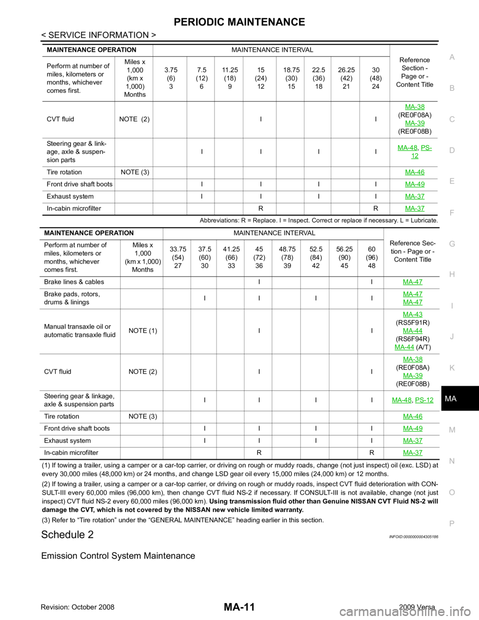
MA
N
O P
Abbreviations: R = Replace. I = Inspect. Corr
ect or replace if necessary. L = Lubricate.
(1) If towing a trailer, using a camper or a car-top carrier, or driving on rough or muddy roads, change (not just inspect) oil (exc. LSD) at
every 30,000 miles (48,000 km) or 24 months, and change LSD gear oil every 15,000 miles (24,000 km) or 12 months.
(2) If towing a trailer, using a camper or a car-top carrier, or driving on rough or muddy roads, inspect CVT fluid deteriorati on with CON-
SULT-III every 60,000 miles (96,000 km), then change CVT fluid NS-2 if necessary. If CONSULT-III is not available, change (not just
inspect) CVT fluid NS-2 every 60,000 miles (96,000 km). Using transmission fluid other than Genuine NISSAN CVT Fluid NS-2 will
damage the CVT, which is not covered by the NISSAN new vehicle limited warranty.
(3) Refer to “Tire rotation” under the “GENERAL MAINTENANCE” heading earlier in this section.
Schedule 2 INFOID:0000000004305186
Emission Control System Maintenance CVT fluid NOTE (2) I I
MA-38
(RE0F08A) MA-39
(RE0F08B)
Steering gear & link-
age, axle & suspen-
sion parts I I I I
MA-48 ,
PS- 12
Tire rotation NOTE (3)
MA-46Front drive shaft boots I I I I
MA-49Exhaust system I I I I
MA-37In-cabin microfilter R R
MA-37Brake pads, rotors,
drums & linings I I I I MA-47 MA-47
Manual transaxle oil or
automatic transaxle fluid NOTE (1) I I MA-43
(RS5F91R) MA-44
(RS6F94R)
MA-44 (A/T)
CVT fluid NOTE (2) I I MA-38
(RE0F08A)
MA-39
(RE0F08B)
Steering gear & linkage,
axle & suspension parts I I I I
MA-48 ,
PS-12 Tire rotation NOTE (3)
MA-46Front drive shaft boots I I I I
MA-49Exhaust system I I I I
MA-37In-cabin microfilter R R
MA-37