2009 NISSAN LATIO check engine
[x] Cancel search: check enginePage 1300 of 4331
![NISSAN LATIO 2009 Service Repair Manual CVT-356< SERVICE INFORMATION >
[RE0F08B]
TRANSAXLE ASSEMBLY
• When installing the cooler outlet tube (1) to the transaxle assembly (2), align the cooler tube bracket (A) against the transax NISSAN LATIO 2009 Service Repair Manual CVT-356< SERVICE INFORMATION >
[RE0F08B]
TRANSAXLE ASSEMBLY
• When installing the cooler outlet tube (1) to the transaxle assembly (2), align the cooler tube bracket (A) against the transax](/manual-img/5/57359/w960_57359-1299.png)
CVT-356< SERVICE INFORMATION >
[RE0F08B]
TRANSAXLE ASSEMBLY
• When installing the cooler outlet tube (1) to the transaxle assembly (2), align the cooler tube bracket (A) against the transaxle as
shown.
• When installing the transaxle to the engine, align t he matching mark on the drive plate with the matching
mark on the torque converter alignment stud.
• When securing the transaxle to the engine, attach the bolts in
accordance with the following standard.
• When installing the drive plate to torque converter nuts, tighten them temporarily. Then tighten the nuts to the specified torque.
• After completing installation check for fluid level, fluid leakage, and the positions of CVT. Refer to CVT-196," Checking CVT Fluid " ,
CVT-345, " Adjustment of CVT Position " and
CVT-345, " Checking of CVT Position " .
• When replacing the CVT assembly, erase EEP ROM in TCM. Refer to CVT-190, " Service After Replacing
TCM and Transaxle Assembly " . WCIA0618E
Bolt No. 1 (Transaxle to engine) 2 (Engine to transaxle)
Number of bolts 2 7
Bolt length
“A” mm (in) 55 (2.17) 50 (1.97)
Tightening torque
N·m (kg-m, ft-lb) 62 (6.3, 46) WCIA0619E
Converter nuts: : 51 N·m (5.2 kg-m, 38 ft-lb)
WCIA0616E
Page 1318 of 4331

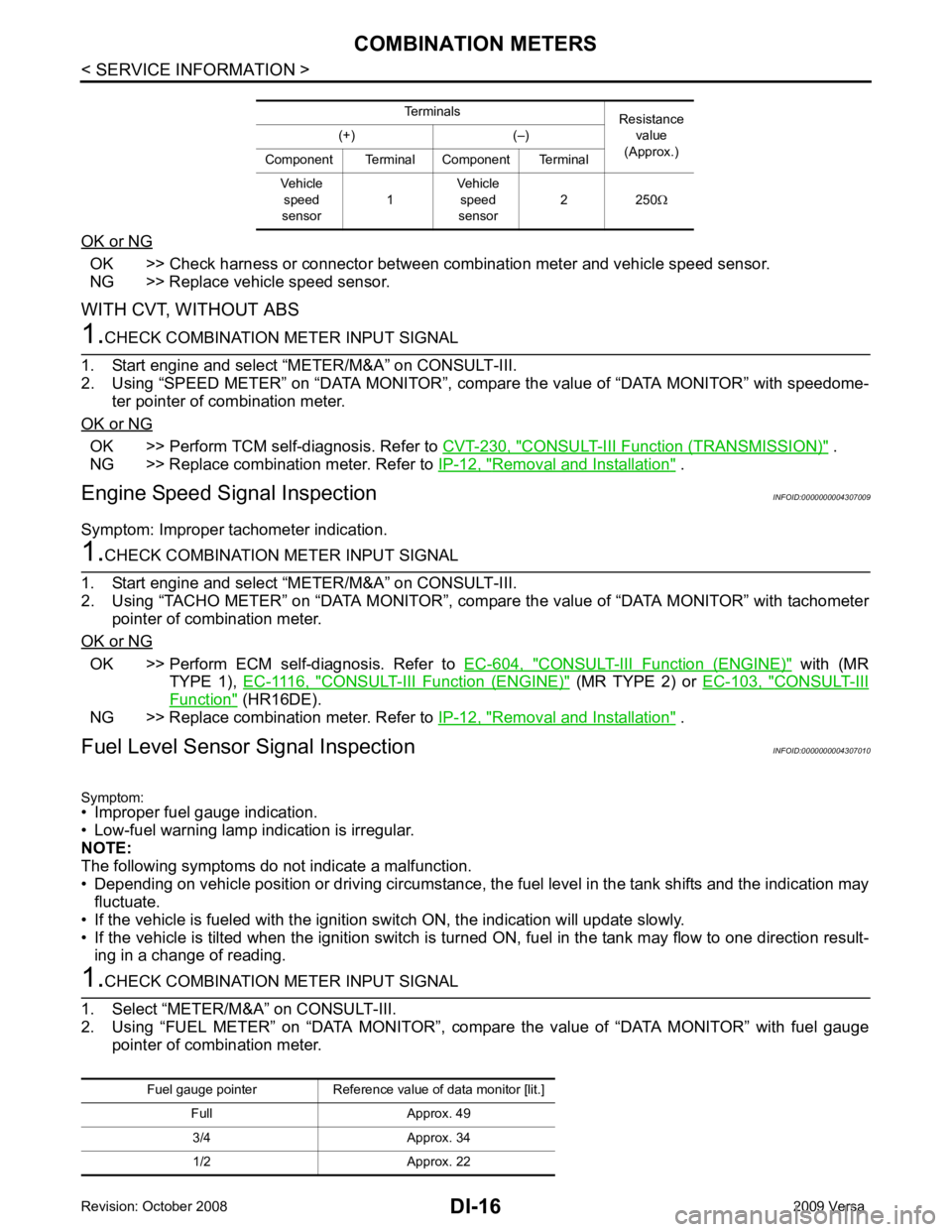
OK >> Check harness or connector between combination meter and vehicle speed sensor.
NG >> Replace vehicle speed sensor.
WITH CVT, WITHOUT ABS OK >> Perform TCM self-diagnosis. Refer to
CVT-230, " CONSULT-III Function (TRANSMISSION) " .
NG >> Replace combination meter. Refer to IP-12, " Removal and Installation " .
Engine Speed Signal Inspection INFOID:0000000004307009
Symptom: Improper tachometer indication. OK >> Perform ECM self-diagnosis. Refer to
EC-604, " CONSULT-III Function (ENGINE) " with (MR
TYPE 1), EC-1116, " CONSULT-III Function (ENGINE) " (MR TYPE 2) or
EC-103, " CONSULT-III
Function " (HR16DE).
NG >> Replace combination meter. Refer to IP-12, " Removal and Installation " .
Fuel Level Sensor Signal Inspection INFOID:0000000004307010
Symptom:
• Improper fuel gauge indication.
• Low-fuel warning lamp indication is irregular.
NOTE:
The following symptoms do not indicate a malfunction.
• Depending on vehicle position or driving circumstance, the fuel level in the tank shifts and the indication may
fluctuate.
• If the vehicle is fueled with the ignition switch ON, the indication will update slowly.
• If the vehicle is tilted when the ignition switch is turned ON, fuel in the tank may flow to one direction result-
ing in a change of reading.
Page 1332 of 4331

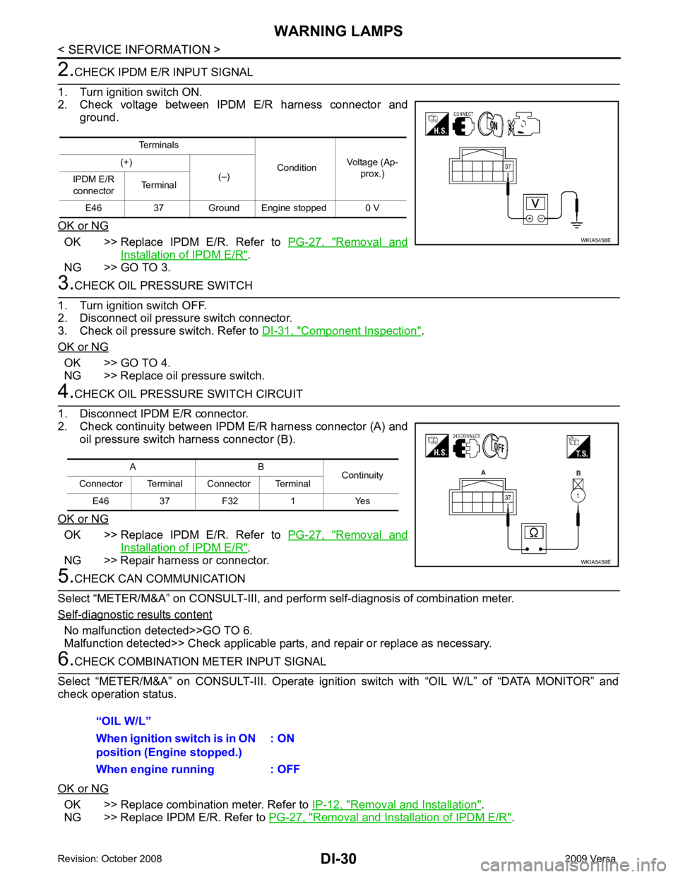
OK >> Replace IPDM E/R. Refer to
PG-27, " Removal and
Installation of IPDM E/R " .
NG >> GO TO 3. Component Inspection " .
OK or NG OK >> GO TO 4.
NG >> Replace oil pressure switch. OK >> Replace IPDM E/R. Refer to
PG-27, " Removal and
Installation of IPDM E/R " .
NG >> Repair harness or connector. - diagnostic results content
No malfunction detected>>GO TO 6.
Malfunction detected>> Check applicable parts, and repair or replace as necessary. OK >> Replace combination meter. Refer to
IP-12, " Removal and Installation " .
NG >> Replace IPDM E/R. Refer to PG-27, " Removal and Installation of IPDM E/R " .
Terminals
ConditionVoltage (Ap-
prox.)
(+)
(–)
IPDM E/R
connector Terminal
E46 37 Ground Engine stopped 0 V
Page 1361 of 4331

EC
A
N
O P
Diagnosis Procedure ...........................................
..
349
P0507 ISC SYSTEM ....................................... ..351
Description .......................................................... ..351
DTC Logic ........................................................... ..351
Diagnosis Procedure ........................................... ..351
P0603 ECM POWER SUPPLY ....................... ..353
Description .......................................................... ..353
DTC Logic ........................................................... ..353
Diagnosis Procedure ........................................... ..353
P0605 ECM ..................................................... ..355
Description .......................................................... ..355
DTC Logic ........................................................... ..355
Diagnosis Procedure ........................................... ..356
P0607 ECM ..................................................... ..357
Description .......................................................... ..357
DTC Logic ........................................................... ..357
Diagnosis Procedure ........................................... ..357
P0643 SENSOR POWER SUPPLY ............... ..358
DTC Logic ........................................................... ..358
Wiring Diagram ................................................... ..359
Diagnosis Procedure ........................................... ..359
P0850 PNP SWITCH ...................................... ..362
Description .......................................................... ..362
DTC Logic ........................................................... ..362
Component Function Check ................................ ..363
Wiring Diagram ................................................... ..364
Diagnosis Procedure ........................................... ..364
P1148 CLOSED LOOP CONTROL ................ ..367
DTC Logic ........................................................... ..367
P1217 ENGINE OVER TEMPERATURE ....... ..368
DTC Logic ........................................................... ..368
Component Function Check ................................ ..368
Diagnosis Procedure ........................................... ..369
P1225 TP SENSOR ........................................ ..372
Description .......................................................... ..372
DTC Logic ........................................................... ..372
Diagnosis Procedure ........................................... ..372
Special Repair Requirem ent .................................373
P1226 TP SENSOR ........................................ ..374
Description .......................................................... ..374
DTC Logic ........................................................... ..374
Diagnosis Procedure ........................................... ..374
Special Repair Requirem ent .................................375
P1421 COLD START CONTROL ................... ..376
Description .......................................................... ..376
DTC Logic ........................................................... ..376
Diagnosis Procedure ........................................... ..376
P1715 INPUT SPEED SENSOR (PRIMARY
SPEED SENSOR) .......................................... ..
378
Description .......................................................... ..378 DTC Logic ............................................................
..378
Diagnosis Procedure ........................................... ..378
P1805 BRAKE SWITCH ................................. 380
Description ........................................................... ..380
DTC Logic ............................................................ ..380
Wiring Diagram .................................................... ..381
Diagnosis Procedure ........................................... ..381
Component Inspection (Stop Lamp Switch) ........ ..383
P2100, P2103 THROTTLE CONTROL MO-
TOR RELAY .................................................... 384
Description ........................................................... ..384
DTC Logic ............................................................ ..384
Wiring Diagram .................................................... ..385
Diagnosis Procedure ........................................... ..385
P2101 ELECTRIC THROTTLE CONTROL
FUNCTION ....... ............................................... 388
Description ........................................................... ..388
DTC Logic ............................................................ ..388
Wiring Diagram .................................................... ..389
Diagnosis Procedure ........................................... ..389
Component Inspection ......................................... ..392
Special Repair Requiremen t ..................................392
P2118 THROTTLE CONTROL MOTOR ......... 393
Description ........................................................... ..393
DTC Logic ............................................................ ..393
Wiring Diagram .................................................... ..394
Diagnosis Procedure ........................................... ..394
Component Inspection ......................................... ..395
Special Repair Requiremen t ..................................396
P2119 ELECTRIC THROTTLE CONTROL
ACTUATOR ..................................................... 397
Description ........................................................... ..397
DTC Logic ............................................................ ..397
Diagnosis Procedure ........................................... ..397
Special Repair Requiremen t ..................................398
P2122, P2123 APP SENSOR ......................... 399
Description ........................................................... ..399
DTC Logic ............................................................ ..399
Wiring Diagram .................................................... ..400
Diagnosis Procedure ........................................... ..400
Component Inspection ......................................... ..402
Special Repair Requiremen t ..................................402
P2127, P2128 APP SENSOR ......................... 403
Description ........................................................... ..403
DTC Logic ............................................................ ..403
Wiring Diagram .................................................... ..404
Diagnosis Procedure ........................................... ..404
Component Inspection ......................................... ..406
Special Repair Requiremen t ..................................407
P2135 TP SENSOR ......................................... 408
Description ........................................................... ..408
DTC Logic ............................................................ ..408
Page 1363 of 4331

EC
A
N
O P
Inspection ............................................................
..
500
ON-VEHICLE REPAIR .... ...........................502
EVAP CANISTER ........................................... ..502
Exploded View .................................................... ..502
Removal and Installation .......................................502
Inspection ............................................................ ..503
SERVICE DATA AND SPECIFICATIONS
(SDS) ......... ................................. ................504
SERVICE DATA AND SPECIFICATIONS
(SDS) .............................................................. ..504
Idle Speed ........................................................... ..504
Ignition Timing ..................................................... ..504
Calculated Load Value ........................................ ..504
Mass Air Flow Sensor ......................................... ..504
MR TYPE 1
SERVICE INFOMATION .. ..........................505
APPLICATION NOTICE ................................. ..505
How to Check Vehicle Type ................................ ..505
INDEX FOR DTC ............................................ ..506
U1000-U1010 ...................................................... ..506
P0011-P0075 ...................................................... ..506
P0101-P0128 ...................................................... ..506
P0130-P0183 ...................................................... ..507
P0222-P0420 ...................................................... ..507
P0441-P0463 ...................................................... ..508
P0500-P0643 ...................................................... ..508
P0705-P0734 ...................................................... ..508
P0740-P0845 ...................................................... ..509
P0850-P1574 ...................................................... ..509
P1610-P1615 ...................................................... ..510
P1705-P1805 ...................................................... ..510
P2100-P2A00 ...................................................... ..510
PRECAUTIONS .............................................. ..512
Precaution for Supplemental Restraint System
(SRS) "AIR BAG" and "SEAT BELT PRE-TEN-
SIONER" ............................................................. ..
512
Precaution for Procedure without Cowl Top Cover ..512
On Board Diagnosis (OBD) System of Engine and
A/T, CVT ............................................................. ..
512
Precaution ........................................................... ..513
PREPARATION .............................................. ..516
Special Service Tool ........................................... ..516
Commercial Service Tool .................................... ..516
ENGINE CONTROL SYSTEM ........................ ..518
Schematic ........................................................... ..518
Multiport Fuel Injection (MFI) System ................. ..518
Electronic Ignition (EI) System ............................ ..521
Fuel Cut Control (at No Load and High Engine
Speed) ................................................................. ..
521
AIR CONDITIONING CUT CONTROL ........... ..523 Input/Output Signal Chart ....................................
..523
System Description .............................................. ..523
AUTOMATIC SPEED CONTROL DEVICE
(ASCD) ............................................................ 524
System Description .............................................. ..524
Component Description ....................................... ..525
CAN COMMUNICATION ................................. 526
System Description .............................................. ..526
EVAPORATIVE EMISSION SYSTEM ............. 527
Description ........................................................... ..527
Component Inspection ......................................... ..529
Removal and Installation ..................................... ..531
How to Detect Fuel Vapor Leakage ..................... ..531
ON BOARD REFUELING VAPOR RECOV-
ERY (ORVR) .................................................... 533
System Description .............................................. ..533
Diagnosis Procedure ........................................... ..533
Component Inspection ......................................... ..535
POSITIVE CRANKCASE VENTILATION ....... 538
Description ........................................................... ..538
Component Inspection ......................................... ..538
NVIS (NISSAN VEHICLE IMMOBILIZER SYS-
TEM-NATS) ..................................................... 540
Description ........................................................... ..540
ON BOARD DIAGNOSTIC (OBD) SYSTEM .. 541
Introduction .......................................................... ..541
Two Trip Detection Logic ..................................... ..541
Emission-related Diagnostic Information ............. ..542
Malfunction Indicator Lamp (MIL) ..........................557
OBD System Operation Chart ............................. ..560
BASIC SERVICE PROCEDURE ..................... 566
Basic Inspection .................................................. ..566
Idle Speed and Ignition Timing Check ................. ..570
Procedure After Replacing ECM ......................... ..571
VIN Registration .................................................. ..572
Accelerator Pedal Released Position Learning ... ..572
Throttle Valve Closed Position Learning ............. ..572
Idle Air Volume Learning ..................................... ..572
Fuel Pressure Check ........................................... ..574
TROUBLE DIAGNOSIS .................................. 577
Trouble Diagnosis Introduction ............................ ..577
DTC Inspection Priority Chart .............................. ..581
Fail-Safe Chart .................................................... ..582
Symptom Matrix Chart ......................................... ..583
Engine Control Component Parts Location ......... ..588
Vacuum Hose Drawing ........................................ ..594
Circuit Diagram .................................................... ..595
ECM Harness Connector Terminal Layout .......... ..597
ECM Terminal and Reference Value ................... ..597
CONSULT-III Function (ENGINE) ....................... ..604
Generic Scan Tool (GST) Function ..................... ..612
Page 1375 of 4331

EC
A
N
O P
DTC P0850 PNP SWITCH ..............................
1401
Component Description ....................................... 1401
CONSULT-III Refe rence Value in Data Monitor
Mode ................................................................... 1401
On Board Diagnosis Logic .................................. 1401
DTC Confirmation Procedure .............................. 1401
Overall Function Check ....................................... 1402
Wiring Diagram ................................................... 1403
Diagnosis Procedure ........................................... 1404
DTC P1148 CLOSED LOOP CONTROL ....... 1407
On Board Diagnosis Logic .................................. 1407
DTC P1217 ENGINE OVER TEMPERATURE 1408
System Description ............................................. 1408
CONSULT-III Refe rence Value in Data Monitor
Mode ................................................................... 1409
On Board Diagnosis Logic .................................. 1409
Overall Function Check ....................................... 1409
Wiring Diagram ................................................... 1411
Diagnosis Procedure ........................................... 1412
Main 13 Causes of Overheating .......................... 1415
Component Inspection ........................................ 1416
DTC P1225 TP SENSOR ............................... 1417
Component Description ....................................... 1417
On Board Diagnosis Logic .................................. 1417
DTC Confirmation Procedure .............................. 1417
Diagnosis Procedure ........................................... 1417
Removal and Installation .....................................1418
DTC P1226 TP SENSOR ............................... 1419
Component Description ....................................... 1419
On Board Diagnosis Logic .................................. 1419
DTC Confirmation Procedure .............................. 1419
Diagnosis Procedure ........................................... 1419
Removal and Installation .....................................1420
DTC P1421 COLD START CONTROL .......... 1421
Description .......................................................... 1421
On Board Diagnosis Logic .................................. 1421
DTC Confirmation Procedure .............................. 1421
Diagnosis Procedure ........................................... 1421
DTC P1564 ASCD STEERING SWITCH ....... 1423
Component Description ....................................... 1423
CONSULT-III Refe rence Value in Data Monitor
Mode ................................................................... 1423
On Board Diagnosis Logic .................................. 1423
DTC Confirmation Procedure .............................. 1424
Wiring Diagram ................................................... 1425
Diagnosis Procedure ........................................... 1426
Component Inspection ........................................ 1428
DTC P1572 ASCD BRAKE SWITCH ............. 1429
Component Description ....................................... 1429
CONSULT-III Refe rence Value in Data Monitor
Mode ................................................................... 1429
On Board Diagnosis Logic .................................. 1429
DTC Confirmation Procedure .............................. 1430Wiring Diagram ....................................................
1431
Diagnosis Procedure ........................................... 1432
Component Inspection ......................................... 1436
DTC P1574 ASCD VEH ICLE SPEED SEN-
SOR ................................................................ 1438
Component Description ....................................... 1438
On Board Diagnosis Logic ................................... 1438
DTC Confirmation Procedure .............................. 1438
Diagnosis Procedure ........................................... 1438
DTC P1715 INPUT SPEED SENSOR (TUR-
BINE REVOLUTION SENSOR) ..................... 1440
Description ........................................................... 1440
CONSULT-III Reference Va lue in Data Monitor
Mode .................................................................... 1440
On Board Diagnosis Logic ................................... 1440
Diagnosis Procedure ........................................... 1440
DTC P1715 INPUT SPEED SENSOR (PRIMA-
RY SPEED SENSOR) ....................................
1441
Description ........................................................... 1441
CONSULT-III Reference Va lue in Data Monitor
Mode .................................................................... 1441
On Board Diagnosis Logic ................................... 1441
DTC Confirmation Procedure .............................. 1441
Diagnosis Procedure ........................................... 1441
DTC P1805 BRAKE SWITCH ........................ 1443
Description ........................................................... 1443
CONSULT-III Reference Va lue in Data Monitor
Mode .................................................................... 1443
On Board Diagnosis Logic ................................... 1443
DTC Confirmation Procedure .............................. 1443
Wiring Diagram .................................................... 1444
Diagnosis Procedure ........................................... 1445
Component Inspection ......................................... 1446
DTC P2100, P2103 THROTTLE CONTROL
MOTOR RELAY ............................................. 1447
Component Description ....................................... 1447
CONSULT-III Reference Va lue in Data Monitor
Mode .................................................................... 1447
On Board Diagnosis Logic ................................... 1447
DTC Confirmation Procedure .............................. 1447
Wiring Diagram .................................................... 1448
Diagnosis Procedure ........................................... 1449
DTC P2101 ELECTRIC THROTTLE CON-
TROL FUNCTION .......................................... 1451
Description ........................................................... 1451
On Board Diagnosis Logic ................................... 1451
DTC Confirmation Procedure .............................. 1451
Wiring Diagram .................................................... 1452
Diagnosis Procedure ........................................... 1453
Component Inspection ......................................... 1456
Removal and Installation ..................................... 1456
DTC P2118 THROTTLE CONTROL MOTOR 1457
Component Description ....................................... 1457
Page 1383 of 4331

EC
NP
O
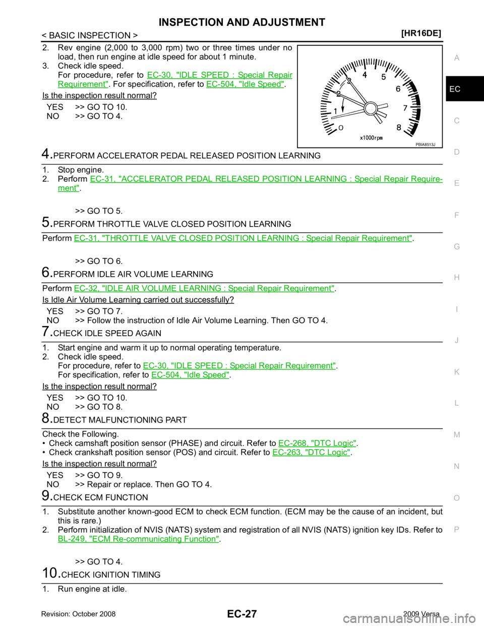
2. Rev engine (2,000 to 3,000 rpm) two or three times under no
load, then run engine at idle speed for about 1 minute.
3. Check idle speed.
For procedure, refer to EC-30, " IDLE SPEED : Special Repair
Requirement " . For specification, refer to
EC-504, " Idle Speed " .
Is the inspection result normal? YES >> GO TO 10.
NO >> GO TO 4. ACCELERATOR PEDAL RELEASED
POSITION LEARNING : Special Repair Require-ment " .
>> GO TO 5. THROTTLE VALVE CLOSED
POSITION LEARNING : Special Repair Requirement " .
>> GO TO 6. IDLE AIR VOLUME LEARNING : Special Repair Requirement " .
Is Idle Air Volume Learning carried out successfully? YES >> GO TO 7.
NO >> Follow the instruction of Idle Air Volume Learning. Then GO TO 4. IDLE SPEED : Special Repair Requirement " .
For specification, refer to EC-504, " Idle Speed " .
Is the inspection result normal? YES >> GO TO 10.
NO >> GO TO 8. DTC Logic " .
• Check crankshaft position sensor (POS) and circuit. Refer to EC-263, " DTC Logic " .
Is the inspection result normal? YES >> GO TO 9.
NO >> Repair or replace. Then GO TO 4. ECM Re-communicating Function " .
>> GO TO 4.
Page 1447 of 4331

EC
NP
O
The 1st trip DTC (whose number is the same as the DT
C number) is displayed for the latest self-diagnostic
result obtained. If the ECM memory was cleared previously , and the 1st trip DTC did not recur, the 1st trip DTC
will not be displayed.
If a malfunction is detected during the 1st trip, the 1st trip DTC is stored in the ECM memory. The MIL will not
light up (two trip detection logic). If the same malfunc tion is not detected in the 2nd trip (meeting the required
driving pattern), the 1st trip DTC is cleared from the ECM memory. If the same malfunction is detected in the
2nd trip, both the 1st trip DTC and DTC are stored in t he ECM memory and the MIL lights up. In other words,
the DTC is stored in the ECM memory and the MIL light s up when the same malfunction occurs in two consec-
utive trips. If a 1st trip DTC is stored and a non-diagnostic operation is performed between the 1st and 2nd
trips, only the 1st trip DTC will continue to be stored. Fo r malfunctions that blink or light up the MIL during the
1st trip, the DTC and 1st trip DTC are stored in the ECM memory.
Procedures for clearing the DTC and the 1st trip DTC fr om the ECM memory are described in “How to Erase
DTC and 1st Trip DTC”.
For malfunctions in which 1st trip DTCs are displayed, refer to EC-475, " DTC Index " . These items are
required by legal regulations to c ontinuously monitor the system/component . In addition, the items monitored
non-continuously are also displayed on CONSULT-III.
1st trip DTC is specified in Service $07 of SAE J1979. 1st trip DTC detection occurs without lighting up the MIL
and therefore does not warn the driver of a malfunction. However, 1st trip DTC detection will not prevent the
vehicle from being tested, for example during Inspection/Maintenance (I/M) tests.
When a 1st trip DTC is detected, check, print out or write down and erase (1st trip) DTC and Freeze Frame
data as specified in Work Flow procedure Step 2, refer to EC-22, " Work Flow " . Then perform DTC CONFIR-
MATION PROCEDURE or Component Function Check to tr y to duplicate the malfunction. If the malfunction is
duplicated, the item requires repair.
Freeze Frame Data and 1st Trip Freeze Frame Data The ECM records the driving conditions such as fuel system status, calculated load value, engine coolant tem-
perature, short-term fuel trim, long-term fuel trim, engi ne speed, vehicle speed, absolute throttle position, base
fuel schedule and intake air temperature at the moment a malfunction is detected.
Data which are stored in the ECM memory, along with the 1st trip DTC, are called 1st trip freeze frame data.
The data, stored together with the DTC data, are ca lled freeze frame data and displayed on CONSULT-III or
GST. The 1st trip freeze frame data can only be di splayed on the CONSULT-III screen, not on the GST.
Only one set of freeze frame data (either 1st trip freez e frame data or freeze frame data) can be stored in the
ECM. 1st trip freeze frame data is stored in the ECM me mory along with the 1st trip DTC. There is no priority
for 1st trip freeze frame data and it is updated each time a different 1st trip DTC is detected. However, once
freeze frame data (2nd trip detection/MIL on) is stored in the ECM memory, 1st trip freeze frame data is no
longer stored. Remember, only one set of freeze frame data can be stored in the ECM. The ECM has the fol-
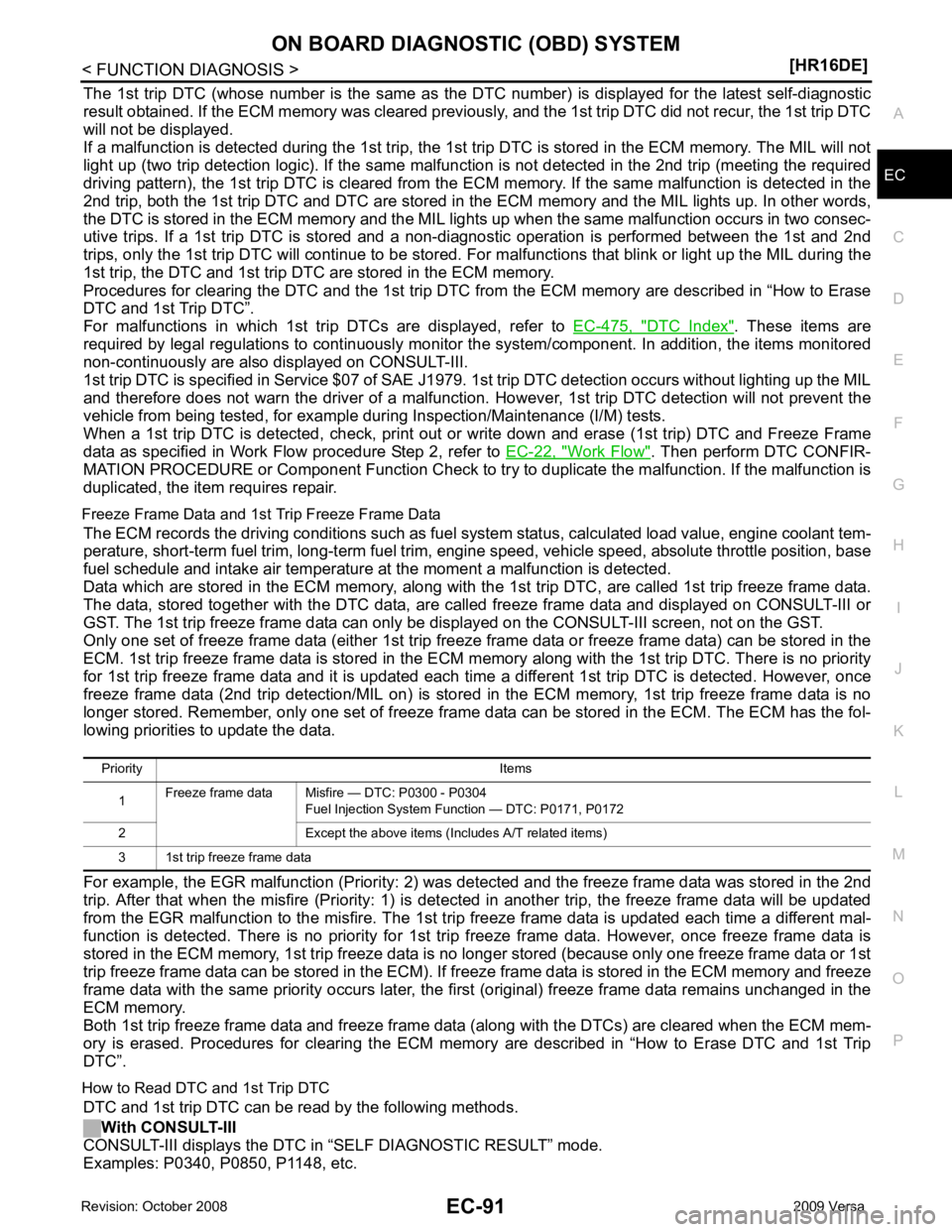
lowing priorities to update the data.
For example, the EGR malfunction (P riority: 2) was detected and the freeze frame data was stored in the 2nd
trip. After that when the misfire (Priority: 1) is detected in another trip, the freeze frame data will be updated
from the EGR malfunction to the misfire. The 1st trip freeze frame data is updated each time a different mal-
function is detected. There is no priority for 1st tr ip freeze frame data. However, once freeze frame data is
stored in the ECM memory, 1st trip freeze data is no longer stored (because only one freeze frame data or 1st
trip freeze frame data can be stored in the ECM). If fr eeze frame data is stored in the ECM memory and freeze
frame data with the same priority occurs later, the first (original) freeze frame data remains unchanged in the
ECM memory.
Both 1st trip freeze frame data and freeze frame dat a (along with the DTCs) are cleared when the ECM mem-
ory is erased. Procedures for clearing the ECM memory are described in “How to Erase DTC and 1st Trip
DTC”.
How to Read DTC and 1st Trip DTC DTC and 1st trip DTC can be read by the following methods.
With CONSULT-III
CONSULT-III displays the DTC in “SELF DIAGNOSTIC RESULT” mode.
Examples: P0340, P0850, P1148, etc. Priority Items
1 Freeze frame data Misfire — DTC: P0300 - P0304
Fuel Injection System Function — DTC: P0171, P0172
2 Except the above items (Includes A/T related items)
3 1st trip freeze frame data