2009 NISSAN LATIO torque
[x] Cancel search: torquePage 3194 of 4331
![NISSAN LATIO 2009 Service Repair Manual EX-10< SERVICE INFORMATION >
[MR18DE]
EXHAUST SYSTEM
• Be careful not to cut your ha nd on heat insulator edges.
CAUTION:
• Use genuine NISSAN exhaust system parts or equi valent, which a NISSAN LATIO 2009 Service Repair Manual EX-10< SERVICE INFORMATION >
[MR18DE]
EXHAUST SYSTEM
• Be careful not to cut your ha nd on heat insulator edges.
CAUTION:
• Use genuine NISSAN exhaust system parts or equi valent, which a](/manual-img/5/57359/w960_57359-3193.png)
EX-10< SERVICE INFORMATION >
[MR18DE]
EXHAUST SYSTEM
• Be careful not to cut your ha nd on heat insulator edges.
CAUTION:
• Use genuine NISSAN exhaust system parts or equi valent, which are specially designed for heat
resistance, corrosion resistance and shape.
REMOVAL
Remove exhaust system components using power tools.
• Remove heated oxygen sensor using Tool as needed.
CAUTION:
Be careful not to damage heated oxygen sensor.
INSTALLATION
Installation is in the reverse order of removal.
CAUTION:
• Always replace exhaust gaskets and seal bear ings with new ones when installing.
• Before installing a new heated oxygen sensor, clean and apply an ti-seize lubricant to exhaust sys-
tem threads using suitable tool.
• Discard any heated oxygen sensor which has been dropped from a height of more than 0.5 m (19.7
in) onto a hard surface such as a co ncrete floor; install a new one.
• Do not over-tighten the heated oxygen sensor. Doing so may damage the heated oxygen sensor,
resulting in the MIL coming on.
• Remove deposits from the sealing surface of each connection. Connect them securely to avoid
exhaust leakage.
• Temporarily tighten nuts on the exhaust manifold side and bolts on the vehicle side. Check each part
for unusual interference, and then ti ghten them to the specified torque.
• When installing each mounting rubb er, avoid twisting or unusual extension in up/down and right/left
directions.
Exhaust Manifold to Exhaust Front Tube
1. Securely insert seal bearing (2) into exhaust manifold (1) side in the direction shown.
• Exhaust front tube (5)
CAUTION:
Be careful not to damage seal bearing surface when install-
ing.
2. Install spring (3), tighten nut (4). • Be careful that the stud bolt nut does not interfere with the
flanged area ( ).
• Make sure the spring (3) sits properly on the flange surface by aligning it to the locator dimples.
Exhaust Front Tube to Center Muffler
1. Securely insert seal bearing (2) into exhaust front tube (1) side in the direction shown.
• Center muffler (5)
CAUTION:
Be careful not to damage seal bearing surface when install-
ing.
2. Install spring (3), tighten bolt (4). • Be careful that the stud bolt does not interfere with the flanged
area ( ).
• Make sure the spring (3) sits properly on the flange surface by
aligning it to the locator dimples.
INSPECTION AFTER INSTALLATION Tool number : KV10114400 (J-38365)
Oxygen sensor thread cleaner : — (J-43897-18)
Oxygen sensor thread cleaner : — (J-43897-12) PBIC3797E
PBIC3798E
Page 3202 of 4331
FAX
N
O P
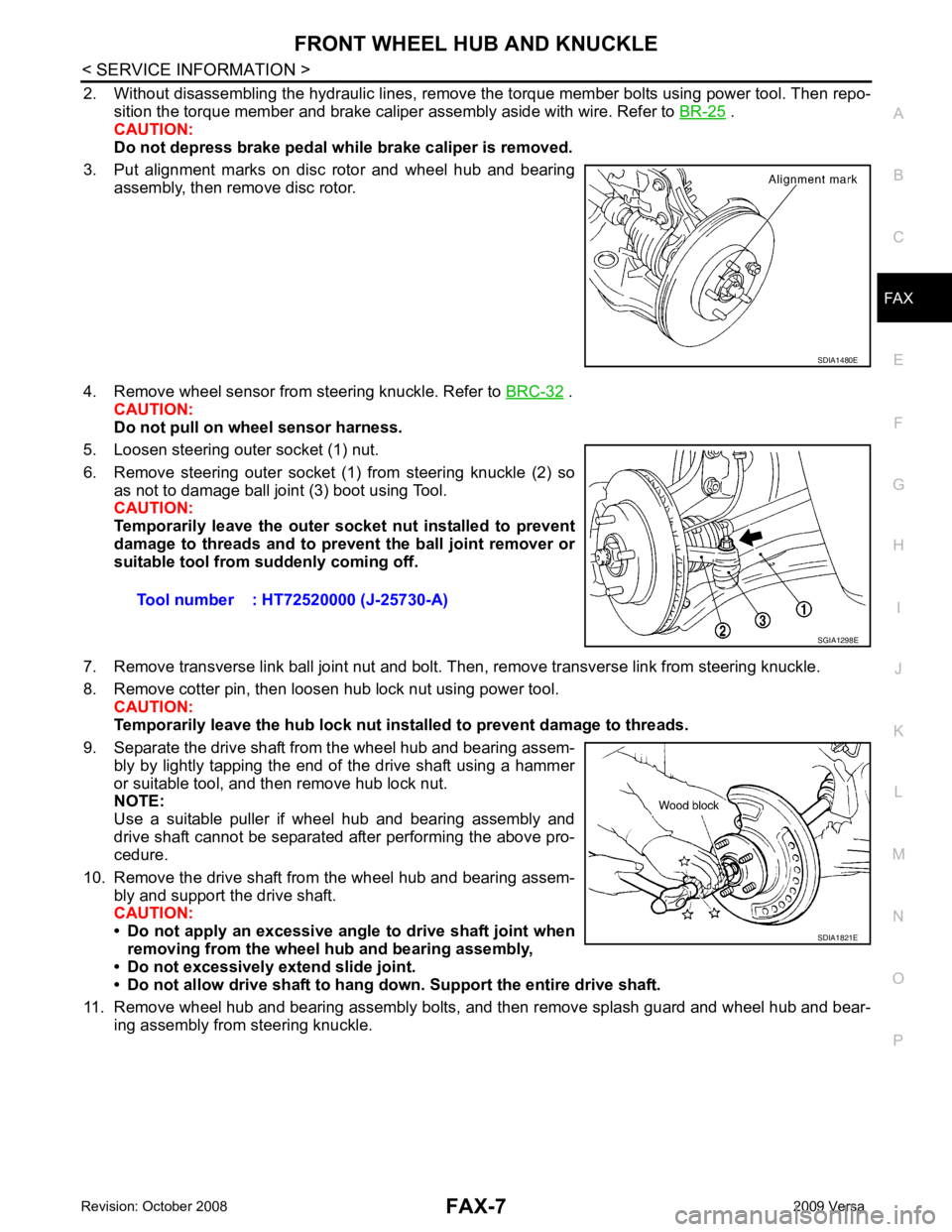
2. Without disassembling the hydraulic lines, remove the torque member bolts using power tool. Then repo-
sition the torque member and brake caliper assembly aside with wire. Refer to BR-25 .
CAUTION:
Do not depress brake pedal while brake caliper is removed.
3. Put alignment marks on disc rotor and wheel hub and bearing assembly, then remove disc rotor.
4. Remove wheel sensor from steering knuckle. Refer to BRC-32 .
CAUTION:
Do not pull on wheel sensor harness.
5. Loosen steering outer socket (1) nut.
6. Remove steering outer socket (1) from steering knuckle (2) so as not to damage ball joint (3) boot using Tool.
CAUTION:
Temporarily leave the outer so cket nut installed to prevent
damage to threads and to pr event the ball joint remover or
suitable tool from suddenly coming off.
7. Remove transverse link ball joint nut and bolt. Then, remove transverse link from steering knuckle.
8. Remove cotter pin, then loosen hub lock nut using power tool. CAUTION:
Temporarily leave the hub lock nut inst alled to prevent damage to threads.
9. Separate the drive shaft from the wheel hub and bearing assem- bly by lightly tapping the end of the drive shaft using a hammer
or suitable tool, and then remove hub lock nut.
NOTE:
Use a suitable puller if wheel hub and bearing assembly and
drive shaft cannot be separated after performing the above pro-
cedure.
10. Remove the drive shaft from the wheel hub and bearing assem- bly and support the drive shaft.
CAUTION:
• Do not apply an excessive angle to drive shaft joint when
removing from the wheel hub and bearing assembly,
• Do not excessively extend slide joint.
• Do not allow drive shaft to hang do wn. Support the entire drive shaft.
11. Remove wheel hub and bearing assembly bolts, and then remove splash guard and wheel hub and bear- ing assembly from steering knuckle.
Page 3203 of 4331
FAX-8< SERVICE INFORMATION >
FRONT WHEEL HUB AND KNUCKLE
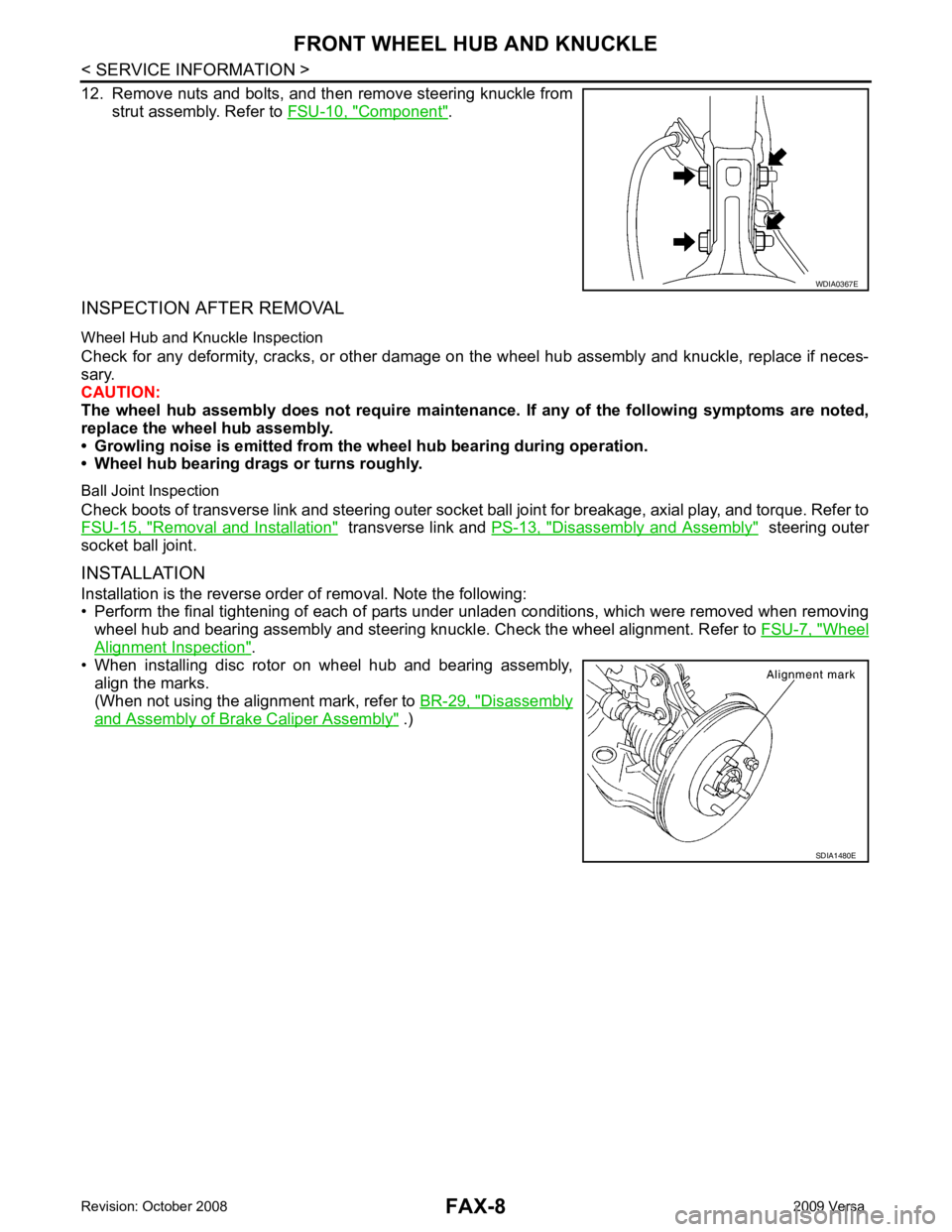
12. Remove nuts and bolts, and then remove steering knuckle from strut assembly. Refer to FSU-10, " Component " .
INSPECTION AFTER REMOVAL
Wheel Hub and Knuckle Inspection
Check for any deformity, cracks, or other damage on t he wheel hub assembly and knuckle, replace if neces-
sary.
CAUTION:
The wheel hub assembly does not require maintenance. If any of the following symptoms are noted,
replace the wheel hub assembly.
• Growling noise is emitted from the wheel hub bearing during operation.
• Wheel hub bearing drags or turns roughly.
Ball Joint Inspection
Check boots of transverse link and steering outer socket ball joint for breakage, axial play, and torque. Refer to
FSU-15, " Removal and Installation " transverse link and
PS-13, " Disassembly and Assembly " steering outer
socket ball joint.
INSTALLATION
Installation is the reverse order of removal. Note the following:
• Perform the final tightening of each of parts under unladen conditions, which were removed when removing
wheel hub and bearing assembly and steering knuckl e. Check the wheel alignment. Refer to FSU-7, " Wheel
Alignment Inspection " .
• When installing disc rotor on wheel hub and bearing assembly,
align the marks.
(When not using the alignment mark, refer to BR-29, " Disassembly
and Assembly of Brake Caliper Assembly " .) WDIA0367E
SDIA1480E
Page 3245 of 4331
FRONT SUSPENSION ASSEMBLY
FSU-11
< SERVICE INFORMATION >
C
D
F
G H
I
J
K L
M A
B FSU
N
O P
Removal and Installation
INFOID:0000000004305866
REMOVAL 1. Separate intermediate shaft from steering gear pinion shaft. Refer to PS-9, " Removal and Installation " .
2. Remove front tires from vehicle using a power tool.
3. Remove wheel sensor from steering knuckle. Refer to BRC-32 .
CAUTION:
Do not pull on wheel sensor harness.
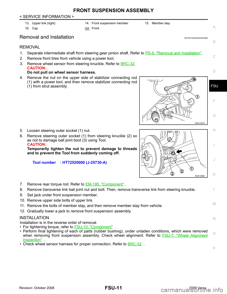
4. Remove the nut on the upper side of stabilizer connecting rod (1) with a power tool, and then remove stabilizer connecting rod
(1) from strut assembly.
5. Loosen steering outer socket (1) nut.
6. Remove steering outer socket (1) from steering knuckle (2) so as not to damage ball joint boot (3) using Tool.
CAUTION:
Temporarily tighten the nut to prevent damage to threads
and to prevent the Tool fr om suddenly coming off.
7. Remove rear torque rod. Refer to EM-195, " Component " .
8. Remove transverse link ball joint nut and bolt. Then, remove transverse link from steering knuckle.
9. Set jack under front suspension member.
10. Remove upper side bolts of upper link.
11. Remove the bolts of member stay, and then remove member stay from vehicle.
12. Gradually lower a jack to remove front suspension assembly.
INSTALLATION Installation is in the reverse order of removal.
• For tightening torque, refer to FSU-10, " Component " .
• Perform final tightening of each of parts (rubber bushing), under unladen conditions, which were removed when removing front suspension assembly. Check wheel alignment. Refer to FSU-7, " Wheel Alignment
Inspection " .
• Check wheel sensor harness for proper connection. Refer to BRC-32 .
13. Upper link (right) 14. Front suspension member 15. Member stay
16. Cap Front SGIA1297E
Tool number : HT72520000 (J-25730-A)
SGIA1298E
Page 3246 of 4331
FSU-12< SERVICE INFORMATION >
COIL SPRING AND STRUT
COIL SPRING AND STRUT
Removal and Installation INFOID:0000000004305867
REMOVAL
1. Remove cowl top panel. Refer to EI-22, " Removal and Installation " .
2. Remove front tires using power tool.
3. Remove harness of wheel sensor from strut assembly. Refer to BRC-32, " Removal and Installation " .
CAUTION:
Do not pull on wheel sensor harness.
4. Remove brake hose lock plate. Refer to BR-12, " Rear Brake Tube and Hose " .
5. Remove the nut on the upper side of stabilizer c onnecting rod using power tool, and then remove stabi-
lizer connecting rod from strut assembly.
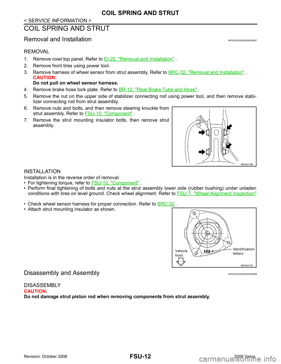
6. Remove nuts and bolts, and then remove steering knuckle from strut assembly. Refer to FSU-10, " Component " .
7. Remove the strut mounting insulator bolts, then remove strut assembly.
INSTALLATION
Installation is in the reverse order of removal.
• For tightening torque, refer to FSU-10, " Component " .
• Perform final tightening of bolts and nuts at the strut assembly lower side (rubber bushing) under unladen
conditions with tires on level ground. Check wheel alignment. Refer to FSU-7, " Wheel Alignment Inspection "
.
• Check wheel sensor harness for proper connection. Refer to BRC-32 .
• Attach strut mounting insulator as shown.
Disassembly and Assembly INFOID:0000000004305868
DISASSEMBLY
CAUTION:
Do not damage strut piston rod when removing components from strut assembly. WEIA0179E
MEIA0014E
Page 3248 of 4331
FSU-14< SERVICE INFORMATION >
COIL SPRING AND STRUT
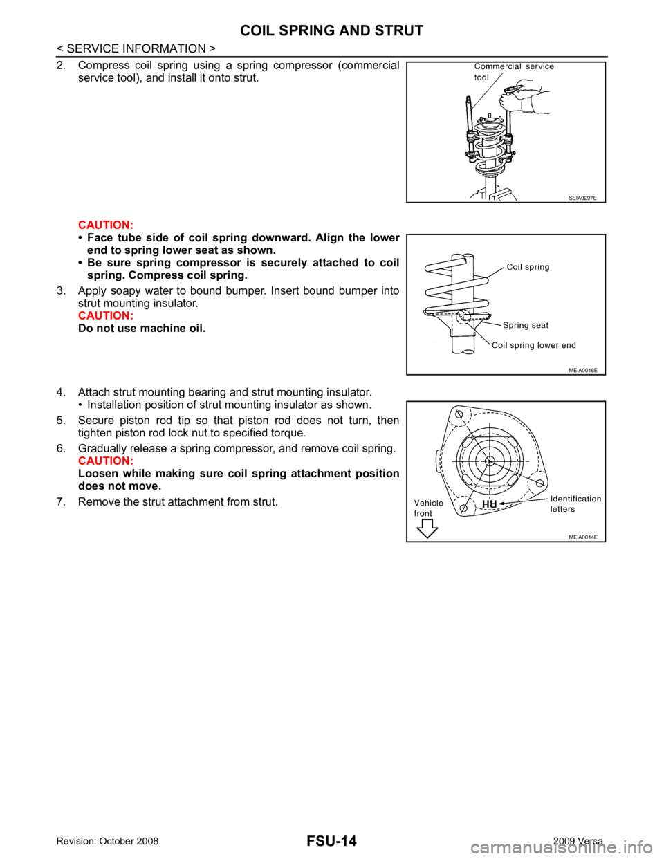
2. Compress coil spring using a spring compressor (commercial service tool), and install it onto strut.
CAUTION:
• Face tube side of coil spri ng downward. Align the lower
end to spring lower seat as shown.
• Be sure spring compressor is securely attached to coil
spring. Compress coil spring.
3. Apply soapy water to bound bumper. Insert bound bumper into strut mounting insulator.
CAUTION:
Do not use machine oil.
4. Attach strut mounting bearing and strut mounting insulator. • Installation position of strut mounting insulator as shown.
5. Secure piston rod tip so that piston rod does not turn, then tighten piston rod lock nut to specified torque.
6. Gradually release a spring compressor, and remove coil spring. CAUTION:
Loosen while making sure co il spring attachment position
does not move.
7. Remove the strut attachment from strut. SEIA0297E
MEIA0016E
MEIA0014E
Page 3249 of 4331
FSU
N
O P
TRANSVERSE LINK
Removal and Installation INFOID:0000000004305869
REMOVAL 1. Remove front tires using power tool.
2. Remove transverse link ball joint nut and bolt. Then, remove transverse link from steering knuckle.
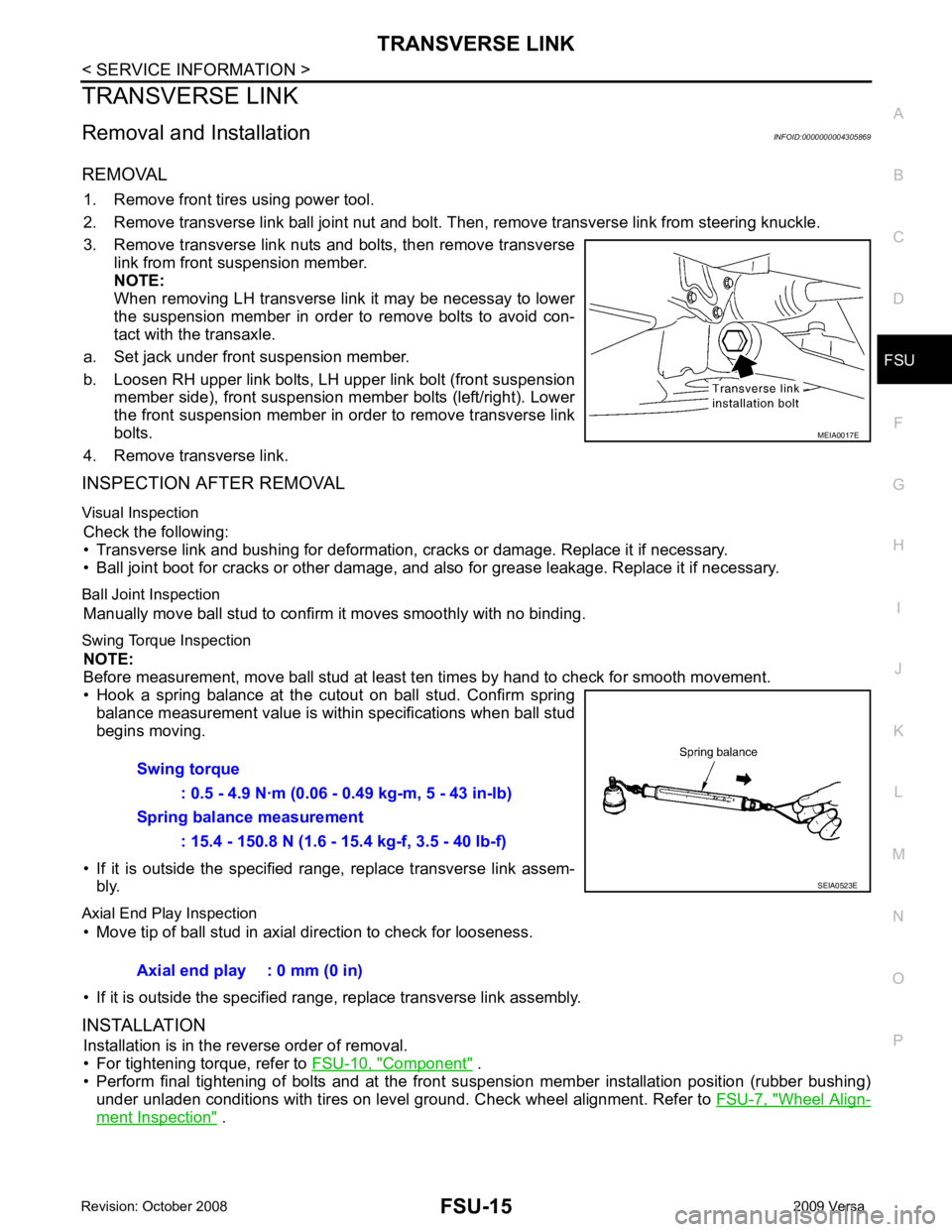
3. Remove transverse link nuts and bolts, then remove transverse link from front suspension member.
NOTE:
When removing LH transverse link it may be necessay to lower
the suspension member in order to remove bolts to avoid con-
tact with the transaxle.
a. Set jack under front suspension member.
b. Loosen RH upper link bolts, LH upper link bolt (front suspension member side), front suspension member bolts (left/right). Lower
the front suspension member in order to remove transverse link
bolts.
4. Remove transverse link.
INSPECTION AFTER REMOVAL
Visual Inspection Check the following:
• Transverse link and bushing for deformation, cracks or damage. Replace it if necessary.
• Ball joint boot for cracks or other damage, and also for grease leakage. Replace it if necessary.
Ball Joint Inspection Manually move ball stud to confirm it moves smoothly with no binding.
Swing Torque Inspection NOTE:
Before measurement, move ball stud at least t en times by hand to check for smooth movement.
• Hook a spring balance at the cutout on ball stud. Confirm spring balance measurement value is within specifications when ball stud
begins moving.
• If it is outside the specified range, replace transverse link assem- bly.
Axial End Play Inspection • Move tip of ball stud in axial direction to check for looseness.
• If it is outside the specified range, replace transverse link assembly.
INSTALLATION Installation is in the reverse order of removal.
• For tightening torque, refer to FSU-10, " Component " .
• Perform final tightening of bolts and at the front suspension member installation position (rubber bushing)
under unladen conditions with tires on level ground. Check wheel alignment. Refer to FSU-7, " Wheel Align-
ment Inspection " .
Page 3250 of 4331
FSU-16< SERVICE INFORMATION >
STABILIZER BAR
STABILIZER BAR
Removal and Installation INFOID:0000000004305870
REMOVAL
1. Separate intermediate shaft from steering gear pinion shaft. Refer to PS-9, " Removal and Installation " .
2. Remove front tires using power tool.
3. Remove the nut on the lower side of stabilizer connec ting rod using power tool, and then remove stabilizer
connecting rod from stabilizer bar.
4. If necessary remove stabilize connecting rod upper nut using power tool. Separate stabilizer connecting rod and strut.
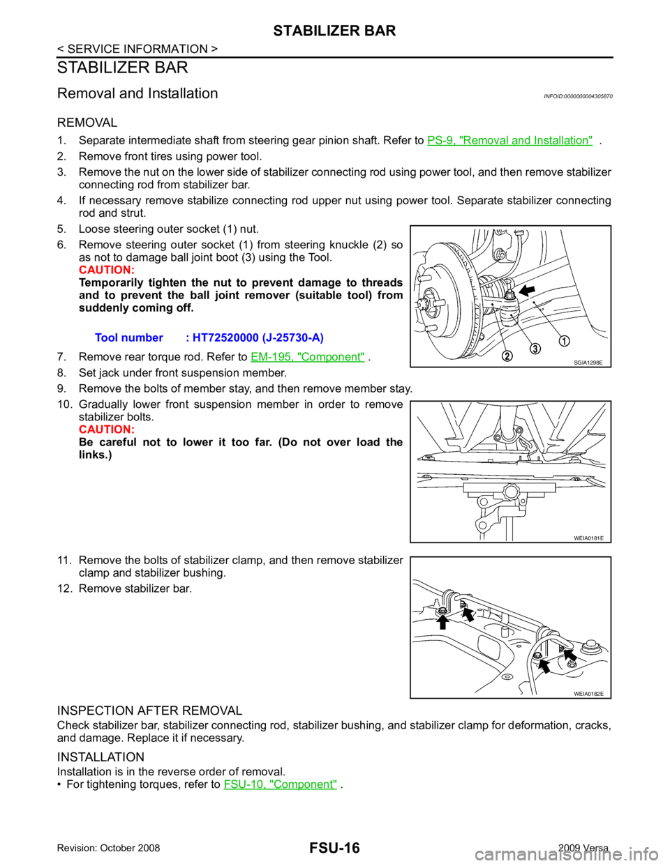
5. Loose steering outer socket (1) nut.
6. Remove steering outer socket (1) from steering knuckle (2) so as not to damage ball joint boot (3) using the Tool.
CAUTION:
Temporarily tighten the nut to prevent damage to threads
and to prevent the ball joint remover (suitable tool) from
suddenly coming off.
7. Remove rear torque rod. Refer to EM-195, " Component " .
8. Set jack under front suspension member.
9. Remove the bolts of member stay, and then remove member stay.
10. Gradually lower front suspension member in order to remove stabilizer bolts.
CAUTION:
Be careful not to lower it too far. (Do not over load the
links.)
11. Remove the bolts of stabilizer clamp, and then remove stabilizer clamp and stabilizer bushing.
12. Remove stabilizer bar.
INSPECTION AFTER REMOVAL
Check stabilizer bar, stabilizer connecting rod, stabilizer bushing, and stabilizer clamp for deformation, cracks,
and damage. Replace it if necessary.
INSTALLATION
Installation is in the reverse order of removal.
• For tightening torques, refer to FSU-10, " Component " .
Tool number : HT72520000 (J-25730-A) SGIA1298E
WEIA0181E
WEIA0182E