2009 NISSAN LATIO torque
[x] Cancel search: torquePage 3125 of 4331
Component " .
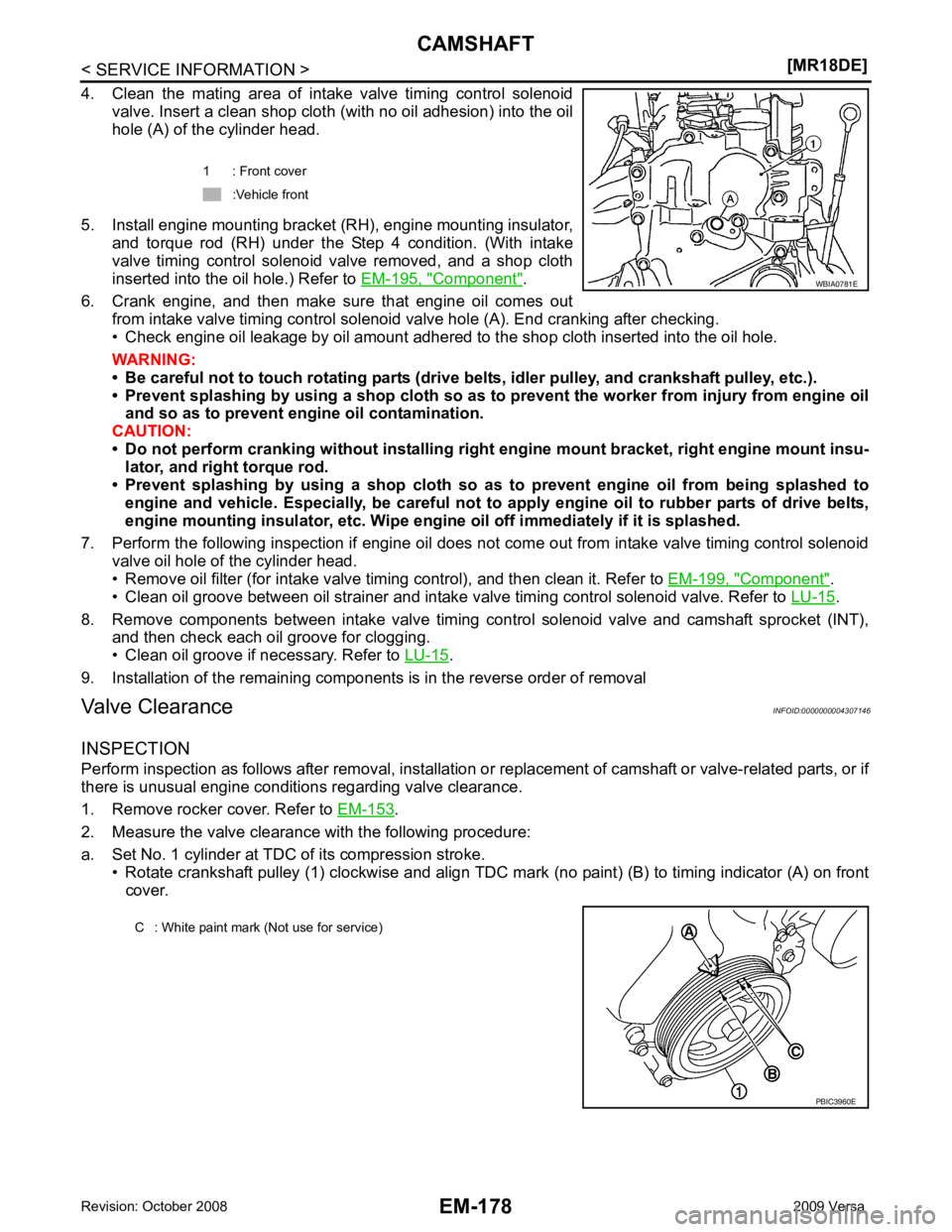
6. Crank engine, and then make sure that engine oil comes out from intake valve timing control solenoid valve hole (A). End cranking after checking.
• Check engine oil leakage by oil amount adhered to the shop cloth inserted into the oil hole.
WARNING:
• Be careful not to touch rotating parts (drive be lts, idler pulley, and crankshaft pulley, etc.).
• Prevent splashing by using a shop cloth so as to prevent the worker from injury from engine oil
and so as to prevent engi ne oil contamination.
CAUTION:
• Do not perform cranking without installing right engine mount bracket, right engine mount insu-
lator, and right torque rod.
• Prevent splashing by using a shop cloth so as to prevent engine oil from being splashed to
engine and vehicle. Especially, be careful not to apply engine oil to rubber parts of drive belts,
engine mounting insulator, etc. Wipe engi ne oil off immediately if it is splashed.
7. Perform the following inspection if engine oil does not come out from intake valve timing control solenoid valve oil hole of the cylinder head.
• Remove oil filter (for intake valve timing control), and then clean it. Refer to EM-199, " Component " .
• Clean oil groove between oil strainer and intake valve timing control solenoid valve. Refer to LU-15 .
8. Remove components between intake valve timing c ontrol solenoid valve and camshaft sprocket (INT),
and then check each oil groove for clogging.
• Clean oil groove if necessary. Refer to LU-15 .
9. Installation of the remaining components is in the reverse order of removal
Valve Clearance INFOID:0000000004307146
INSPECTION
Perform inspection as follows after removal, installation or replacement of camshaft or valve-related parts, or if
there is unusual engine conditions regarding valve clearance.
1. Remove rocker cover. Refer to EM-153 .
2. Measure the valve clearance with the following procedure:
a. Set No. 1 cylinder at TDC of its compression stroke. • Rotate crankshaft pulley (1) clockwise and align TDC mark (no paint) (B) to timing indicator (A) on front
cover. 1 : Front cover
:Vehicle front
Page 3142 of 4331
EM
NP
O
ENGINE ASSEMBLY
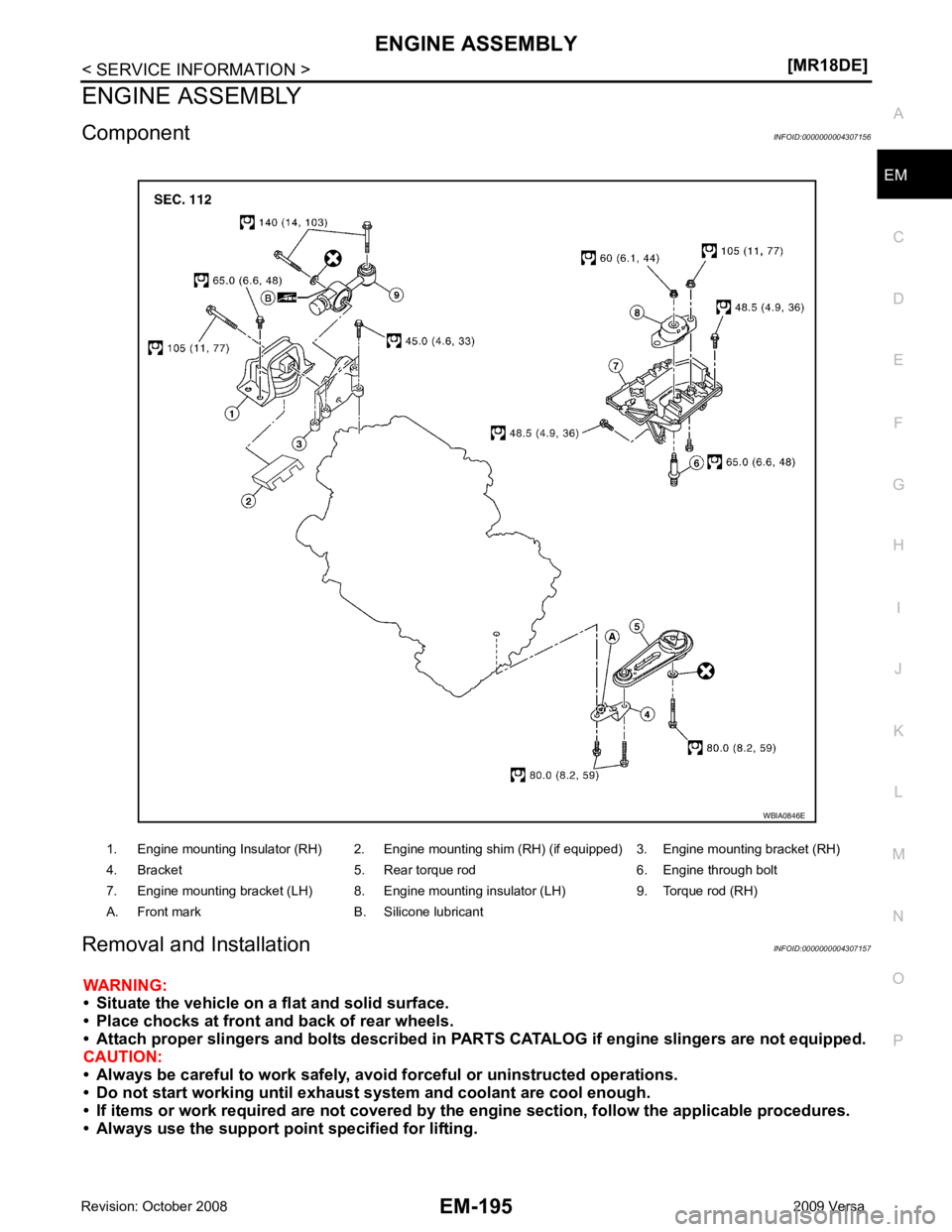
Component INFOID:0000000004307156
Removal and Installation INFOID:0000000004307157
WARNING:
• Situate the vehicle on a flat and solid surface.
• Place chocks at front and back of rear wheels.
• Attach proper slingers and bolts described in P ARTS CATALOG if engine slingers are not equipped.
CAUTION:
• Always be careful to work safely, avoid forceful or uninstructed operations.
• Do not start working until exhaust system and coolant are cool enough.
• If items or work required are not covered by th e engine section, follow the applicable procedures.
• Always use the support poin t specified for lifting.
1. Engine mounting Insulator (RH) 2. Engine mounting shim (RH) (if equipped) 3. Engine mounting bracket (RH)
4. Bracket 5. Rear torque rod 6. Engine through bolt
7. Engine mounting bracket (LH) 8. Engine mounting insulator (LH) 9. Torque rod (RH)
A. Front mark B. Silicone lubricant
Page 3143 of 4331
Garage Jack and
Safety Stand and 2-Pole Lift " .
REMOVAL
Remove the engine and the transaxle assembly from t he vehicle downward. Separate the engine and the tran-
saxle.
1. Remove engine undercover.
2. Drain engine coolant from radiator. Refer to CO-35, " Changing Engine Coolant " .
CAUTION:
• Perform this step when the engine is cold.
• Do not spill engine coolant on drive belt.
3. Remove front fender protector (RH and LH). Refer to EI-24 .
4. Remove exhaust front tube. Refer to EX-9 .
5. Remove drive shafts (LH and RH) from steering knuckle. Refer to FAX-9 .
6. Remove transaxle joint bolts which pierce at oil pan (upper) lower rear side. Refer to AT-232 (A/T models),
CVT-182 or
CVT-354 (CVT models) or
MT-58 (M/T models).
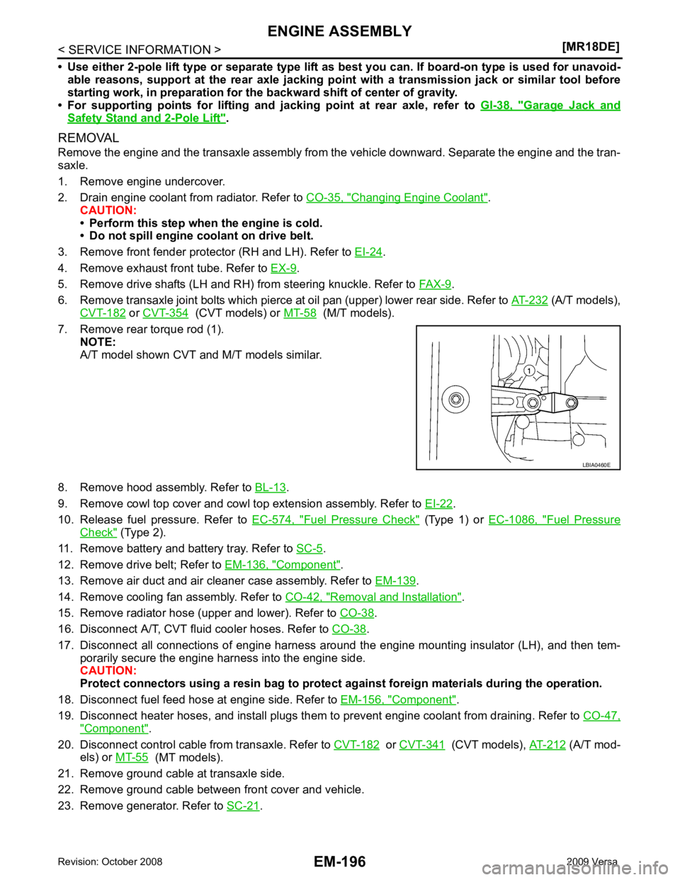
7. Remove rear torque rod (1). NOTE:
A/T model shown CVT and M/T models similar.
8. Remove hood assembly. Refer to BL-13 .
9. Remove cowl top cover and cowl top extension assembly. Refer to EI-22 .
10. Release fuel pressure. Refer to EC-574, " Fuel Pressure Check " (Type 1) or
EC-1086, " Fuel Pressure
Check " (Type 2).
11. Remove battery and battery tray. Refer to SC-5 .
12. Remove drive belt; Refer to EM-136, " Component " .
13. Remove air duct and air cleaner case assembly. Refer to EM-139 .
14. Remove cooling fan assembly. Refer to CO-42, " Removal and Installation " .
15. Remove radiator hose (upper and lower). Refer to CO-38 .
16. Disconnect A/T, CVT fluid cooler hoses. Refer to CO-38 .
17. Disconnect all connections of engine harness around the engine mounting insulator (LH), and then tem- porarily secure the engine harness into the engine side.
CAUTION:
Protect connectors using a resin bag to protect against foreign materials during the operation.
18. Disconnect fuel feed hose at engine side. Refer to EM-156, " Component " .
19. Disconnect heater hoses, and install plugs them to prevent engine coolant from draining. Refer to CO-47," Component " .
20. Disconnect control cable from transaxle. Refer to CVT-182 or
CVT-341 (CVT models),
AT-212 (A/T mod-
els) or MT-55 (MT models).
21. Remove ground cable at transaxle side.
22. Remove ground cable between front cover and vehicle.
23. Remove generator. Refer to SC-21 .
Page 3144 of 4331
EM
NP
O
24. Remove A/C compressor with piping connected from t
he engine. Temporarily secure it on the vehicle side
with a rope to avoid putting load on it. Refer to MTC-80, " Removal and Installation of Compressor -
MR18DE " .
25. Remove the intake manifold to prevent the hanging chain from interfering. Refer to EM-141, " Compo-
nent " .
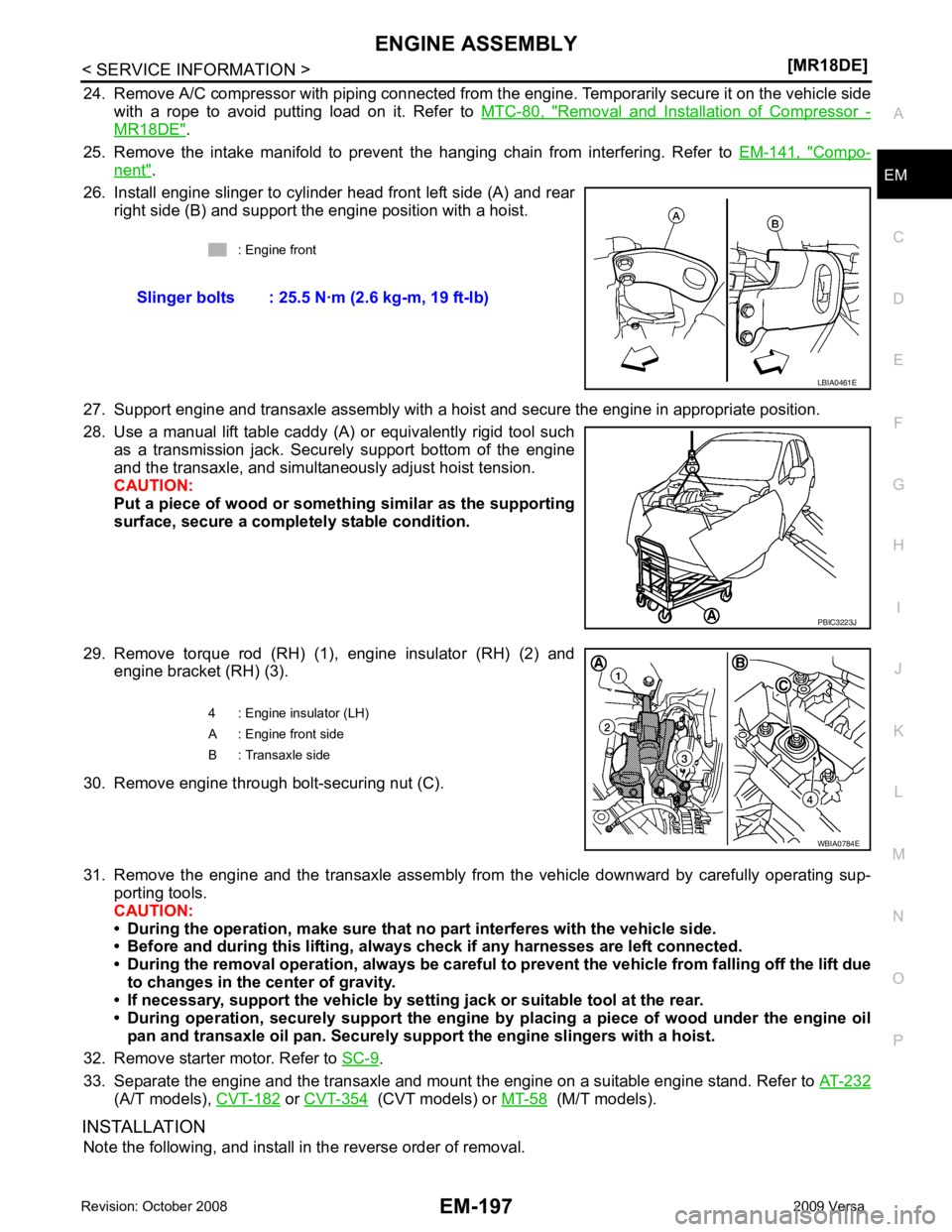
26. Install engine slinger to cylinder head front left side (A) and rear right side (B) and support the engine position with a hoist.
27. Support engine and transaxle assembly with a hoist and secure the engine in appropriate position.
28. Use a manual lift table caddy (A) or equivalently rigid tool such as a transmission jack. Securely support bottom of the engine
and the transaxle, and simultaneously adjust hoist tension.
CAUTION:
Put a piece of wood or someth ing similar as the supporting
surface, secure a completely stable condition.
29. Remove torque rod (RH) (1), engine insulator (RH) (2) and engine bracket (RH) (3).
30. Remove engine through bolt-securing nut (C).
31. Remove the engine and the transaxle assembly from the vehicle downward by carefully operating sup- porting tools.
CAUTION:
• During the operation, make sure that no part interferes with the vehicle side.
• Before and during this lifting, alw ays check if any harnesses are left connected.
• During the removal operation, alw ays be careful to prevent the vehicle from falling off the lift due
to changes in the center of gravity.
• If necessary, support the vehicle by setting jack or suitable tool at the rear.
• During operation, securely suppor t the engine by placing a piece of wood under the engine oil
pan and transaxle oil pan. Securely sup port the engine slingers with a hoist.
32. Remove starter motor. Refer to SC-9 .
33. Separate the engine and the transaxle and mount the engine on a suitable engine stand. Refer to AT-232(A/T models),
CVT-182 or
CVT-354 (CVT models) or
MT-58 (M/T models).
INSTALLATION Note the following, and install in the reverse order of removal. : Engine front
Slinger bolts : 25.5 N·m (2.6 kg-m, 19 ft-lb) PBIC3223J
Page 3145 of 4331
Com-
ponent " .
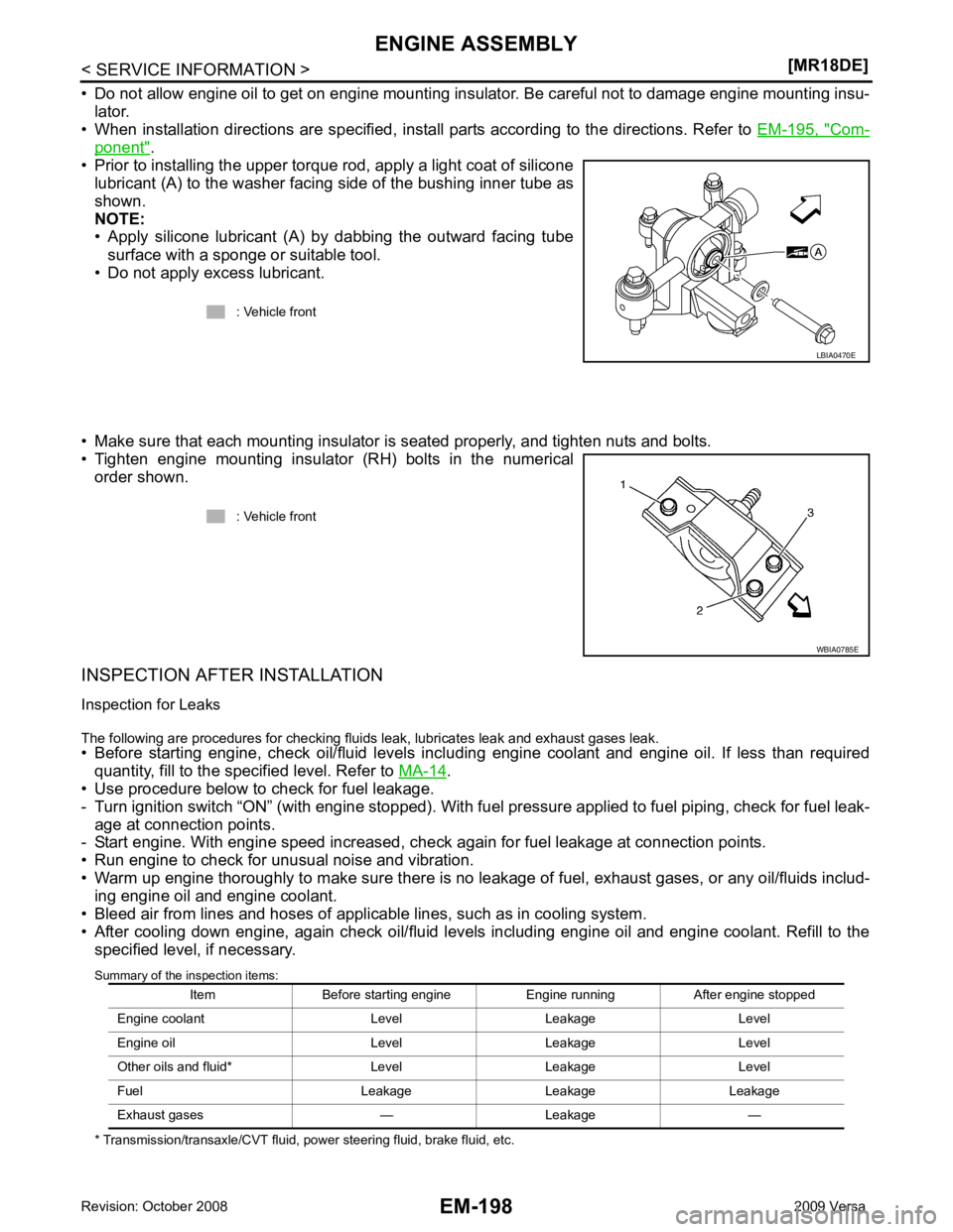
• Prior to installing the upper torque rod, apply a light coat of silicone lubricant (A) to the washer facing side of the bushing inner tube as
shown.
NOTE:
• Apply silicone lubricant (A) by dabbing the outward facing tube
surface with a sponge or suitable tool.
• Do not apply excess lubricant.
• Make sure that each mounting insulator is seated properly, and tighten nuts and bolts.
• Tighten engine mounting insulator (RH) bolts in the numerical order shown.
INSPECTION AFTER INSTALLATION
Inspection for Leaks
The following are procedures for checking fluids leak, lubricates leak and exhaust gases leak.
• Before starting engine, check oil/fluid levels incl uding engine coolant and engine oil. If less than required
quantity, fill to the specified level. Refer to MA-14 .
• Use procedure below to check for fuel leakage.
- Turn ignition switch “ON” (with engine stopped). With fuel pressure applied to fuel piping, check for fuel leak-
age at connection points.
- Start engine. With engine speed increased, che ck again for fuel leakage at connection points.
• Run engine to check for unusual noise and vibration.
• Warm up engine thoroughly to make sure there is no leak age of fuel, exhaust gases, or any oil/fluids includ-
ing engine oil and engine coolant.
• Bleed air from lines and hoses of applicable lines, such as in cooling system.
• After cooling down engine, again check oil/fluid levels including engine oil and engine coolant. Refill to the specified level, if necessary.
Summary of the inspection items:
* Transmission/transaxle/CVT fluid, power steering fluid, brake fluid, etc. : Vehicle front
Page 3166 of 4331
EM
NP
O
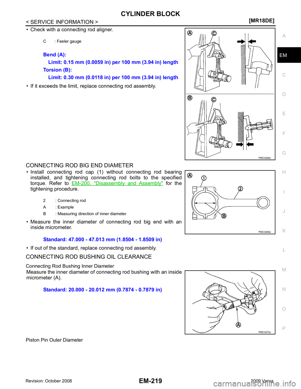
• Check with a connecting rod aligner.
• If it exceeds the limit, replace connecting rod assembly.
CONNECTING ROD BIG END DIAMETER • Install connecting rod cap (1) without connecting rod bearing installed, and tightening connecting rod bolts to the specified
torque. Refer to EM-200, " Disassembly and Assembly " for the
tightening procedure.
• Measure the inner diameter of connecting rod big end with an inside micrometer.
• If out of the standard, replace connecting rod assembly.
CONNECTING ROD BUSHING OIL CLEARANCE
Connecting Rod Bush ing Inner Diameter
Measure the inner diameter of connecting rod bushing with an inside
micrometer (A).
Piston Pin Outer Diameter C : Feeler gauge
Bend (A): Limit: 0.15 mm (0.0059 in) per 100 mm (3.94 in) length
Torsion (B): Limit: 0.30 mm (0.0118 in) per 100 mm (3.94 in) length
Page 3170 of 4331
EM
NP
O
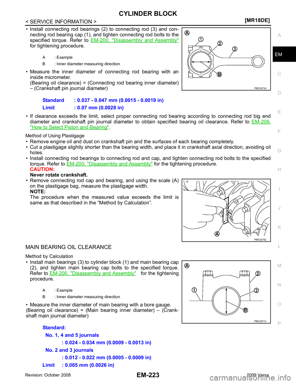
• Install connecting rod bearings (2) to connecting rod (3) and con-
necting rod bearing cap (1), and tighten connecting rod bolts to the
specified torque. Refer to EM-200, " Disassembly and Assembly "
for tightening procedure.
• Measure the inner diameter of connecting rod bearing with an inside micrometer.
(Bearing oil clearance) = (Connecting rod bearing inner diameter)
– (Crankshaft pin journal diameter)
• If clearance exceeds the limit, select proper c onnecting rod bearing according to connecting rod big end
diameter and crankshaft pin journal diameter to obtain specified bearing oil clearance. Refer to EM-209," How to Select Piston and Bearing " .
Method of Using Plastigage • Remove engine oil and dust on crankshaft pin and the surfaces of each bearing completely.
• Cut a plastigage slightly shorter than the bearing width, and place it in crankshaft axial direction, avoiding oil
holes.
• Install connecting rod bearings to connecting rod and c ap, and tighten connecting rod bolts to the specified
torque. Refer to EM-200, " Disassembly and Assembly " for the tightening procedure.
CAUTION:
Never rotate crankshaft.
• Remove connecting rod cap and bearing, and using the scale (A) on the plastigage bag, measure the plastigage width.
NOTE:
The procedure when the measured value exceeds the limit is
same as that described in the “Method by Calculation”.
MAIN BEARING OIL CLEARANCE
Method by Calculation • Install main bearings (3) to cylinder block (1) and main bearing cap (2), and tighten main bearing cap bolts to the specified torque.
Refer to EM-200, " Disassembly and Assembly " for the tightening
procedure.
• Measure the inner diameter of main bearing with a bore gauge.
(Bearing oil clearance) = (Main bearing inner diameter) – (Crank-
shaft main journal diameter) A : Example
B : Inner diameter measuring direction
Standard : 0.037 - 0.047 mm (0.0015 - 0.0019 in)
Limit : 0.07 mm (0.0028 in)
Page 3171 of 4331
How to Select
Piston and Bearing " .
Method of Using Plastigage
• Remove engine oil and dust on crankshaft main journal and the surfaces of each bearing completely.
• Cut a plastigage slightly shorter than the bearing width, and place it in crankshaft axial direction, avoiding oil
holes.
• Install main bearings to cylinder block and main bearing cap, and tighten main bearing cap bolts to the spec- ified torque. Refer to EM-200, " Disassembly and Assembly " for the tightening procedure.
CAUTION:
Never rotate crankshaft.
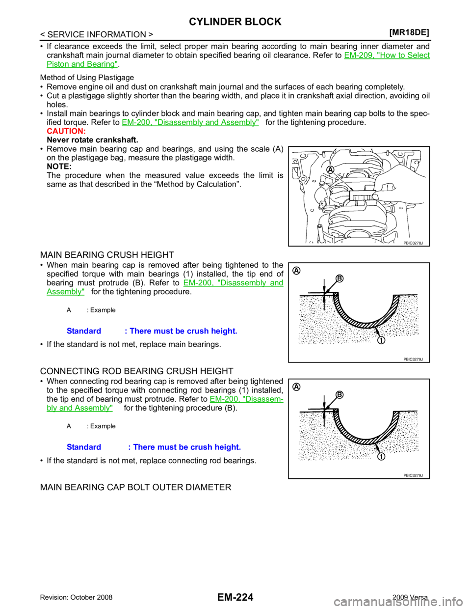
• Remove main bearing cap and bearings, and using the scale (A) on the plastigage bag, measure the plastigage width.
NOTE:
The procedure when the measured value exceeds the limit is
same as that described in the “Method by Calculation”.
MAIN BEARING CRUSH HEIGHT
• When main bearing cap is removed after being tightened to the specified torque with main bearings (1) installed, the tip end of
bearing must protrude (B). Refer to EM-200, " Disassembly and
Assembly " for the tightening procedure.
• If the standard is not met, replace main bearings.
CONNECTING ROD BEARING CRUSH HEIGHT
• When connecting rod bearing cap is removed after being tightened to the specified torque with connecting rod bearings (1) installed,
the tip end of bearing must protrude. Refer to EM-200, " Disassem-
bly and Assembly " for the tightening procedure (B).
• If the standard is not met, replace connecting rod bearings.
MAIN BEARING CAP BOLT OUTER DIAMETER