Page 3786 of 4331

MA
N
O P
M/T OIL : Refilling (RS5F91R)
INFOID:0000000004803422
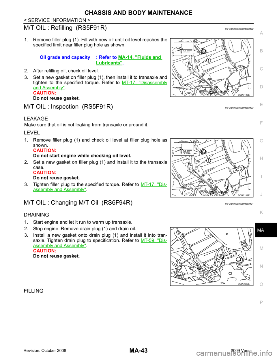
1. Remove filler plug (1). Fill with new oil until oil level reaches the specified limit near filler plug hole as shown.
2. After refilling oil, check oil level.
3. Set a new gasket on filler plug (1), then install it to transaxle and tighten to the specified torque. Refer to MT-17, " Disassembly
and Assembly " .
CAUTION:
Do not reuse gasket.
M/T OIL : Inspection (RS5F91R) INFOID:0000000004803423
LEAKAGE Make sure that oil is not leaking from transaxle or around it.
LEVEL 1. Remove filler plug (1) and check oil level at filler plug hole as shown.
CAUTION:
Do not start engine while checking oil level.
2. Set a new gasket on filler plug (1) and install it to the transaxle case.
CAUTION:
Do not reuse gasket.
3. Tighten filler plug to the specified torque. Refer to MT-17, " Dis-
assembly and Assembly " .
M/T OIL : Changing M/T Oil (RS6F94R) INFOID:0000000004803424
DRAINING 1. Start engine and let it run to warm up transaxle.
2. Stop engine. Remove drain plug (1) and drain oil.
3. Install a new gasket onto drain plug (1) and install it into tran- saxle. Tighten drain plug to specification. Refer to MT-59, " Dis-
assembly and Assembly " .
CAUTION:
Do not reuse gasket.
FILLING Oil grade and capacity : Refer to
MA-14, " Fluids and
Lubricants " .
SCIA7622E
Page 3788 of 4331

MA
N
O P
Do not overfill.
4. Drive vehicle for approximately 5 minutes.
5. Re-check A/T fluid level at A/T fluid temperatures of 50° to 80 °C (122 ° to 176 °F) using “HOT” range on A/
T fluid level gauge.
CAUTION:
• When wiping the A/T fluid level gauge, always use lint-free cloth.
• Firmly fix the A/T fluid level ga uge to the A/T fluid charging pipe using the stopper attached.
6. Check A/T fluid condition and make any necessary repairs. Refer to AT-51, " Inspections Before Trouble
Diagnosis " . If the A/T fluid contains frictional material (clu
tches, bands, etc.), or if the A/T is repaired, over-
hauled, or replaced, inspect and clean the A/T fluid cooler mounted in the radiator. Refer to AT-18, " A/T
Fluid Cooler Cleaning " .
7. Install the removed A/T fluid level gauge into the A/T fluid charging pipe. CAUTION:
Firmly fix the A/T fluid level gaug e to the A/T fluid charging pipe using the stopper attached.
A/T FLUID : Changing A/T Fluid INFOID:0000000004803431
1. Warm up A/T fluid.
2. Stop engine.
3. Drain A/T fluid by removing the drain plug. Re install the drain plug to the specified torque.
CAUTION:
Do not reuse drain plug gasket.
4. Refill the transaxle with new specified A/T fluid th rough the A/T fluid charging pipe. Always refill the tran-
saxle with the same volume of A/T fluid that was drained out.
5. Run engine at idle speed for 5 minutes.
6. Check A/T fluid level and condition. Refer to MA-44, " A/T FLUID : Checking A/T Fluid " .
WHEELS
WHEELS : Balancing Wheels INFOID:0000000004683837
Adjust wheel balance using road wheel center.
CAUTION:
• Be careful not to scratch th e road wheel during removal.
• Use clip-on type wheel balance weights only.
Wheel balance (Maximum allowable unbalance): Drain plug: Refer to
AT-236, " Component " .
Fluid grade and capacity: Refer to MA-14 .
Maximum allowable unbalance Dynamic (At rim flange) Less than 5 g (0.18 oz) (one side)
Static (At rim flange) Less than 10 g (0.35 oz)
Page 3789 of 4331

MA-46< SERVICE INFORMATION >
CHASSIS AND BODY MAINTENANCE
WHEELS : Rotation INFOID:0000000004683838
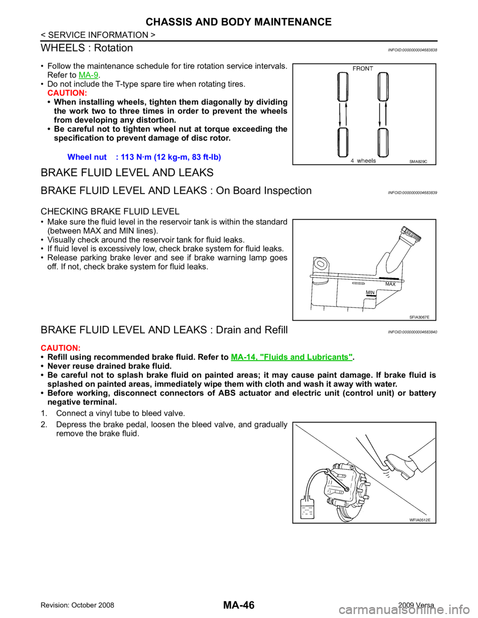
• Follow the maintenance schedule for tire rotation service intervals. Refer to MA-9 .
• Do not include the T-type spare tire when rotating tires.
CAUTION:
• When installing wheels, tighten them diagonally by dividing
the work two to three times in order to prevent the wheels
from developing any distortion.
• Be careful not to tighten wheel nut at torque exceeding the specification to prevent damage of disc rotor.
BRAKE FLUID LEVEL AND LEAKS
BRAKE FLUID LEVEL AND LEAK S : On Board Inspection INFOID:0000000004683839
CHECKING BRAKE FLUID LEVEL
• Make sure the fluid level in the reservoir tank is within the standard (between MAX and MIN lines).
• Visually check around the reservoir tank for fluid leaks.
• If fluid level is excessively low, check brake system for fluid leaks.
• Release parking brake lever and see if brake warning lamp goes off. If not, check brake system for fluid leaks.
BRAKE FLUID LEVEL AND LE AKS : Drain and Refill INFOID:0000000004683840
CAUTION:
• Refill using recommended brake fluid. Refer to MA-14, " Fluids and Lubricants " .
• Never reuse drained brake fluid.
• Be careful not to splash brake fluid on painted areas; it may cause paint damage. If brake fluid is
splashed on painted areas, immediately wipe th em with cloth and wash it away with water.
• Before working, disconnect connectors of ABS actua tor and electric unit (control unit) or battery
negative terminal.
1. Connect a vinyl tube to bleed valve.
2. Depress the brake pedal, loosen the bleed valve, and gradually remove the brake fluid.Wheel nut : 113 N·m (12 kg-m, 83 ft-lb) SMA829C
SFIA3067E
WFIA0512E
Page 3804 of 4331
![NISSAN LATIO 2009 Service Repair Manual MT-10< SERVICE INFORMATION >
[RS5F91R]
M/T OIL
M/T OIL
Draining INFOID:0000000004784220
1. Start engine and let it run to warm up transaxle.
2. Stop engine. Remove drain plug (1) and drain oil.
3. Set NISSAN LATIO 2009 Service Repair Manual MT-10< SERVICE INFORMATION >
[RS5F91R]
M/T OIL
M/T OIL
Draining INFOID:0000000004784220
1. Start engine and let it run to warm up transaxle.
2. Stop engine. Remove drain plug (1) and drain oil.
3. Set](/manual-img/5/57359/w960_57359-3803.png)
MT-10< SERVICE INFORMATION >
[RS5F91R]
M/T OIL
M/T OIL
Draining INFOID:0000000004784220
1. Start engine and let it run to warm up transaxle.
2. Stop engine. Remove drain plug (1) and drain oil.
3. Set a new gasket on drain plug (1) and install it to transaxle and tighten drain plug to the specified torque. Refer to MT-17, " Dis-
assembly and Assembly " .
CAUTION:
Do not reuse gasket.
Refilling INFOID:0000000004784221
1. Remove filler plug (1). Fill with new oil until oil level reaches the specified limit near filler plug hole as shown.
2. After refilling oil, check oil level.
3. Set a new gasket on filler plug (1), then install it to transaxle and tighten to the specified torque. Refer to MT-17, " Disassembly
and Assembly " .
CAUTION:
Do not reuse gasket.
Inspection INFOID:0000000004784222
LEAKAGE
Make sure that oil is not leaking from transaxle or around it.
LEVEL
1. Remove filler plug (1) and check oil level at filler plug hole as shown.
CAUTION:
Do not start engine wh ile checking oil level.
2. Set a new gasket on filler plug (1) and install it to the transaxle case.
CAUTION:
Do not reuse gasket.
3. Tighten filler plug to the specified torque. Refer to MT-17, " Dis-
assembly and Assembly " . PCIB1504E
Oil grade and capacity : Refer to
MA-14, " Fluids and
Lubricants " .
SCIA7119E
SCIA7119E
Page 3810 of 4331
Removal and Installa-
tion " .
REMOVAL
1. Drain gear oil. Refer to MT-10, " Draining " (RS5F91R),
MT-52, " Changing M/T Oil " (RS6F94R).
2. Drain clutch fluid and remove clutch tube from CSC. Refer to CL-12, " Removal and Installation " .
CAUTION:
Do not depress clutch pedal during removal procedure.
3. Remove the engine and transaxle as an assembly from the vehicle. Refer to EM-88, " Removal and Instal-
lation " (HR16DE),
EM-195, " Removal and Installation " (MR18DE).
4. Remove the transaxle to engine and engine to transaxle bolts.
5. Separate the transaxle assembly from the engine.
INSTALLATION 1. LH engine mount bracket (transaxle
side) 2. Transaxle assembly 3. Rear engine mount bracket
4. Washer 5. Rear torque rod ⇐: Front
: Refer to installation.
Page 3811 of 4331

MT
N
O P
Installation is in the reverse order of removal.
CAUTION:
• Make sure the transaxle assembly does not interfer e with the wire harnesses and clutch tube.
• When installing transaxle assembly, do not bring input shaft into contact with clutch cover.
• If transaxle is removed from the vehicle, always replace CSC. Refer to CL-12, " Removal and Installa-
tion " .
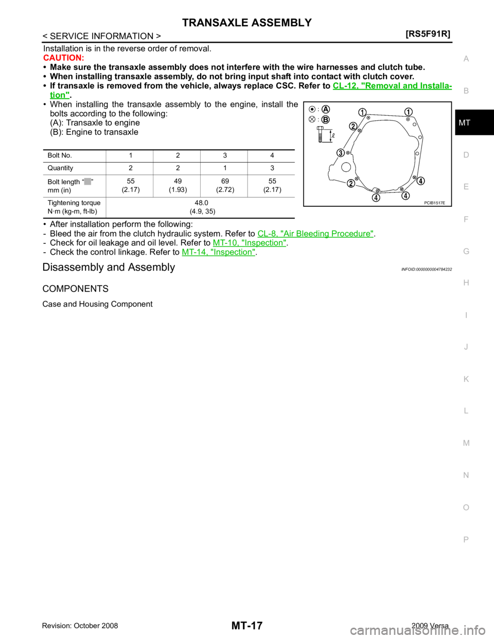
• When installing the transaxle assembly to the engine, install the bolts according to the following:
(A): Transaxle to engine
(B): Engine to transaxle
• After installation perform the following:
- Bleed the air from the clutch hydraulic system. Refer to CL-8, " Air Bleeding Procedure " .
- Check for oil leakage and oil level. Refer to MT-10, " Inspection " .
- Check the control linkage. Refer to MT-14, " Inspection " .
Disassembly and Assembly INFOID:0000000004784232
COMPONENTS
Case and Housing Component Bolt No. 1 2 3 4
Quantity 2 2 1 3
Bolt length “ ”
mm (in) 55
(2.17) 49
(1.93) 69
(2.72) 55
(2.17)
Tightening torque
N·m (kg-m, ft-lb) 48.0
(4.9, 35)
Page 3822 of 4331
Exploded View " .
CAUTION:
Replace control shaft and selector as a set.
7. Install selector to control shaft, and then install retaining pin ( ) to selector using a suitable tool.
CAUTION:
• Be careful with the orientation of selector.
• Replace control shaft and selector as a set.
• Never reuse retaining pin.
8. Install gear catch, spring, and bushing to transaxle case, and then tighten bolt ( ) to the specified torque. Refer to MT-16," Exploded View " .
CAUTION:
Replace gear catch, spring, and bushing as a set.
9. Install oil gutter to transaxle case. Tool number A: ST35300000 ( — )
JPDIC0636ZZ
PCIB1540E
JPDIC0533ZZ
Page 3827 of 4331
![NISSAN LATIO 2009 Service Repair Manual TRANSAXLE ASSEMBLY
MT-33
< SERVICE INFORMATION >
[RS5F91R] D
E
F
G H
I
J
K L
M A
B MT
N
O P
33. Rotate input shaft so that bearing and shaft fit each other, and
then tighten transaxle bolts NISSAN LATIO 2009 Service Repair Manual TRANSAXLE ASSEMBLY
MT-33
< SERVICE INFORMATION >
[RS5F91R] D
E
F
G H
I
J
K L
M A
B MT
N
O P
33. Rotate input shaft so that bearing and shaft fit each other, and
then tighten transaxle bolts](/manual-img/5/57359/w960_57359-3826.png)
TRANSAXLE ASSEMBLY
MT-33
< SERVICE INFORMATION >
[RS5F91R] D
E
F
G H
I
J
K L
M A
B MT
N
O P
33. Rotate input shaft so that bearing and shaft fit each other, and
then tighten transaxle bolts ( ) to the specified torque. Refer to
MT-16, " Exploded View " .
34. Apply recommended sealant to position switch thread and check ball plug thread. Tighten them to transaxle case and them to the
specified torque. Refer to MT-16, " Exploded View " .
• Use Genuine Silicone RTV or an equivalent. GI-42, " Rec-
ommended Chemical Product and Sealant " .
CAUTION:
Never allow old liquid gasket, mo isture, oil, or foreign mat-
ter to remain on thread.
35. Apply gear oil to mainshaft spline.
36. Install 5th main gear (1) to mainshaft using a suitable bolt (A) [M10 x 1.0] and a suitable nut (B).
37. Install adapter plate (1), bushing (2), and 5th input gear (3) to input shaft.
CAUTION:
Be careful with the orientation of adapter plate.
• : Transaxle case side
38. Install 5th-reverse synchronizer hub, 5th-reverse c oupling sleeve, and 5th-reverse shift fork according to
the following procedures.
a. Apply gear oil to 5th-reverse baulk ring.
b. Install 5th-reverse baulk ring (1) to 5th input gear. CAUTION:
Be careful with the orientation of 5th-reverse baulk ring.
c. Install synchronizer levers (2) to 5th-reverse synchronizer hub (3).
CAUTION:
• Replace 5th-reverse synchronizer hub and 5th-reverse coupling sleeve as a set.
• Be careful with the orientation of synchronizer lever.
• : 5th-reverse synchronizer hub side
d. Install 5th-reverse synchronizer hub assembly and washer to input shaft.
CAUTION: JPDIC0610ZZ
PCIB1554E
PCIB1555E
JPDIC0421ZZ